US5890581A - Feeding arrangement for mailed items - Google Patents
Feeding arrangement for mailed items Download PDFInfo
- Publication number
- US5890581A US5890581A US08/700,171 US70017196A US5890581A US 5890581 A US5890581 A US 5890581A US 70017196 A US70017196 A US 70017196A US 5890581 A US5890581 A US 5890581A
- Authority
- US
- United States
- Prior art keywords
- mailed
- linear conveyor
- rotary body
- mailed items
- items
- Prior art date
- Legal status (The legal status is an assumption and is not a legal conclusion. Google has not performed a legal analysis and makes no representation as to the accuracy of the status listed.)
- Expired - Lifetime
Links
Images


Classifications
-
- B—PERFORMING OPERATIONS; TRANSPORTING
- B07—SEPARATING SOLIDS FROM SOLIDS; SORTING
- B07C—POSTAL SORTING; SORTING INDIVIDUAL ARTICLES, OR BULK MATERIAL FIT TO BE SORTED PIECE-MEAL, e.g. BY PICKING
- B07C1/00—Measures preceding sorting according to destination
- B07C1/02—Forming articles into a stream; Arranging articles in a stream, e.g. spacing, orientating
- B07C1/04—Forming a stream from a bulk; Controlling the stream, e.g. spacing the articles
-
- B—PERFORMING OPERATIONS; TRANSPORTING
- B07—SEPARATING SOLIDS FROM SOLIDS; SORTING
- B07C—POSTAL SORTING; SORTING INDIVIDUAL ARTICLES, OR BULK MATERIAL FIT TO BE SORTED PIECE-MEAL, e.g. BY PICKING
- B07C1/00—Measures preceding sorting according to destination
- B07C1/02—Forming articles into a stream; Arranging articles in a stream, e.g. spacing, orientating
- B07C1/025—Devices for the temporary stacking of objects provided with a stacking and destacking device (interstack device)
Definitions
- the invention relates to an arrangement for feeding transport containers of a sorting conveyor with flat mailed items, wherein the arrangement has a linear conveyor which engages one surface of the respective mailed items in a planar frictional lock for the transfer of the mailed items to the transport containers.
- Arrangements of this type are used, for example, in post offices for sorting of letters according to their mailing addresses.
- the letters are fed to the feeding arrangement after their mailing addresses have been captured.
- a sorting conveyor then transports the letters to collection points predetermined by the mailing addresses.
- a feeding arrangement of the above-described type which transfers flat mailed items deposited on a linear conveyor embodied as a conveyor belt extending downward at an angle to the transport containers circulating below the conveyor belt.
- the transport containers are embodied as transport pouches which can be opened and are secured to a conveyor chain.
- the planar frictional lock between the one surface of the mailed items and the conveyor belt i.e., a frictional lock extending longitudinally as well as perpendicularly to the direction of conveyance, ensures that, during the transfer, the conveyor belt adequately carries along standard mailed items and that, thus, the transported items are transferred to the transport containers in a reliable manner.
- the frictional lock between the mailed item and the conveyor belt is cancelled under the influence of turbulent air flows caused by the transport motion and that a disturbance of the transfer occurs.
- European Patent Application EP-A-0 519 375 discloses a feeding arrangement for the transfer of flat mailed items to transport containers of a sorting conveyor wherein, for transfer to the transport containers, the mailed items are conveyed in a roll gap formed between a rotatable roller and a clamping roller.
- the clamping roller is only applied to the mailed items after the mailed items have been deposited on a depositing surface through which the rotatable roller extends. This ensures a reliable transfer of the mailed items even when they are not oriented precisely parallel to the depositing surface.
- a large clamping force is necessary between the rotatable roller and the clamping roller for the conveyance of the mailed items in the roll gap. This may result in damage when delicate mailed items are transferred, for example, packages containing eyeglass lenses or the like.
- an arrangement for feeding transport containers of a sorting conveyor with flat mailed items comprising: a linear conveyor, having a direction of conveyance and a rearward end, for engaging one surface of the respective mailed items in a planar frictional lock and transferring the mailed items in the direction of conveyance to the transport containers at the rearward end of the linear conveyor; and a rotary body having a cylindrical surface including a contact region and being rotatable around an axis extending perpendicularly to the direction of conveyance of the linear conveyor, the rotary body being arranged at the rearward end of the linear conveyor for contacting an opposite surface of the respective mailed items in a frictionally locked manner with the contact region of its cylindrical surface during transfer of the mailed items to the transport vehicles.
- the rolling contact of the rotary body on the other, opposite surface of the mailed items i.e., on the surface facing away from the linear conveyor, ensures a planar frictional lock between the one surface of the mailed items and the linear conveyor due to the inner stiffness of the mailed items, even though the frictional lock between the contact region of the rotary body and the mailed items extends only perpendicularly to the direction of conveyance.
- the mailed items are reliably carried along by the linear conveyor during the transfer.
- it is sufficient that the contact region of the rotary body apply a relatively small force to the mailed items, which excludes the possibility of damage to delicate mailed items.
- the force action of the rotary body must merely effect the maintenance of the planar frictional lock between the mailed item and the linear conveyor, but not the actual conveyance of the mailed items for the transfer to the transport containers. Since the contact region only contacts the other surface at the rearward end of the linear conveyor in the direction of conveyance, it is ensured that the planar frictional lock and thus a reliable carrying along of the mailed items is maintained until the mailed items leave the linear conveyor.
- the arrangement according to the invention can make a sufficient amount of space available to reliably feed the mailed items to the linear conveyor without impairing the operational reliability during the transfer to the transport containers, because the use of the rotary body can ensure a reliable guidance of the mailed items even without using a guide wall extending parallel to the linear conveyor or similar guiding elements impeding access to the linear conveyor.
- a combined use of the linear conveyor, which engages the one surface of the mailed items in a frictional lock, and of the rotary body, which contacts the side of the mailed items facing away from the linear conveyor increases the reliability during the feeding of the mailed items to the linear conveyor, on the one hand, and, on the other hand, allows a gentle transfer of delicate mailed items to the transport containers.
- the linear conveyor can be embodied in a particularly simple manner in the form of a conveyor belt, thus at the same time ensuring a maximum frictional lock between the mailed items and the linear conveyor.
- the rotary body can be embodied in a particularly simple manner if the contact region has the shape of a section of a cylindrical surface of a circular cylinder whose cylinder axis coincides with the rotary axis of the rotary body. This can simultaneously accomplish a uniform force action upon the mailed items by the rotary body in a direction extending perpendicularly to the direction of conveyance.
- the reliability of the transfer of the mailed items to the transport containers can be further increased if, during the transfer, the contact region is forced against the other surface by a pretensioning device. This can prevent a cancellation of the planar frictional lock between the one surface of the mailed items and the linear conveyor in a particularly reliable manner.
- the pretensioning force of the pretensioning device can be set to prevent damage of delicate mailed items.
- the rotary body is advisably fastened to a frame which is pivotable around a pivot axis extending parallel to the rotary axis.
- the pretensioning device engage the frame.
- the rotary body preferably with a motor coupled to it, is driven at a rotating speed which is adjusted to the conveying speed of the linear conveyor.
- a particularly precise adjustment of the rotating speed of the rotary body to the conveying speed of the linear conveyor, especially to changes of the conveying speed, can be accomplished if only one motor is used to drive both the linear conveyor and the rotary body.
- the conveying arrangement for the transfer of the mailed items to the transport containers, in which the conveying arrangement engages one surface of the mailed items in a frictionally locked manner, and has a rotary body that is rotatable around a rotary axis extending perpendicularly to the direction of conveyance of the conveying arrangement, which rotary body contacts the other face surface of the mailed items during feeding in a frictionally locked manner, that the rotary body include a region that, in a rotational position of the rotary body, forms a stop for the mailed items to be conveyed by the conveying arrangement.
- the rotary body can effect a reliable guidance of the mailed items during the transfer and, on the other, it can prevent an undesirable displacement of the mailed items relative to the conveying arrangement before the transfer if the rotary body remains in the rotational position in which it forms the stop for the mailed items until the transfer begins.
- the stop can be embodied in a particularly simple manner by a stop region of the cylindrical surface of the rotary body extending in an axial plane of the rotary body. At the same time, such a stop can serve to orient the generally rectangular mailed items along the stop region before the transfer. This further contributes to increasing the operational reliability of the feeding arrangement.
- the cylindrical surface of the rotary body has a guide region transitioning in the direction of rotation to the stop region for guiding the mailed items that are to be fed to the conveying arrangement.
- the rotary body thus serves altogether three functions, namely, on the one hand, a guidance of the mailed items during the transfer, on the other hand, securing the mailed items transferred to the conveying arrangement before the transfer to the transport containers and, finally, a guidance of the mailed items during the feeding to the conveying arrangement.
- the guide region can be embodied in a particularly simple manner if it is disposed in a plane that is parallel to the rotary axis and if it has a smaller distance from the rotary axis than the contact region.
- the direction of conveyance is advisably provided with a component oriented in the direction of gravity so as to exploit the force of gravity.
- the transfer of the mailed items to the transport containers in increments of predetermined lengths of the mailed items can be controlled in a particularly reliable manner by means of an incremental transmitter.
- the mailed items can be fed to the feeding arrangement in a direction that extends perpendicularly to their direction of conveyance.
- FIG. 1 is a schematic, side view of an embodiment of a feeding arrangement according to the invention.
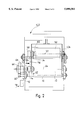
- FIG. 2 is a plan view of the feeding arrangement according to FIG. 1.
- FIG. 3 is schematic, side view of an alternative embodiment of a feeding arrangement according to the invention.
- a feeding arrangement including a linear conveyor embodied as a conveyor belt 10 extending downward at an angle and circulating around a drive roller 12 and a deflection roller 14.
- transport containers 40 circulating below conveyor belt 10
- transport containers are embodied as pouches that can be opened by using a cam track (not shown)
- mailed items are fed to conveyor belt 10 in a substantially vertical orientation, i.e. in the position indicated in FIG. 1 by reference numeral 20, and from the side, i. e., in a direction indicated by arrow 24 in FIG. 2 which is perpendicular to the direction of conveyance of conveyor belt 10.
- the mailed items are then deposited on an upper run 16 of the conveyor belt 10, as is indicated by the mailed item identified by reference numeral 22 in FIG. 1.
- the one surface 21 of the mailed item is placed in a planar frictionally locked engagement with upper run 16 of conveyor belt 10.
- Stop region 34 of a cylindrical surface of a rotary body 30 which is rotatable around a rotary axis 32 extending perpendicularly to the direction of conveyance of conveyor belt 10. Stop region 34 is disposed in a radial plane of rotary body 30 and is formed by a stop rib 33 of rotary body 30. Stop region 34 additionally serves to orient an edge of the mailed items parallel to rotary axis 32.
- drive roller 12 is coupled to a motor 72 via a first shaft 62 (see FIG. 2) connected to drive roller 12 in a manner fixed against relative rotation and extending coaxially to it, a first toothed wheel 60 connected to first shaft 62 in a manner fixed against relative rotation, a second toothed wheel 66, which is secured in a manner fixed against relative rotation to a second shaft 64 extending parallel to first shaft 62 and which meshes with first toothed wheel 60, a driving disk 68 fixed to second shaft 64 in a manner fixed against relative rotation, and a first driving belt 70.
- Motor 72 additionally drives rotary body 30 to rotate around axis 32 in a direction identified by arrow 39 (see FIG. 1) so that a contact region 38 of the cylindrical surface of rotary body 30 contacts a surface 23 of the mailed item facing away from conveyor belt 10 during the transfer of the mailed item.
- the coupling of rotary body 30 to motor 72 is set such that, during the transfer, the circumferential speed of contact region 38 corresponds to the conveying speed of conveyor belt 10.
- rotary body 30 is secured in a manner fixed against relative rotation on a third shaft 80 extending coaxially to rotary axis 32 and parallel to second shaft 64 and is coupled to motor 72 via a third driving disk 78 secured to third shaft 80 in a manner fixed against relative rotation, a second driving belt 76, a driving disk 74 secured to second shaft 64 in a manner fixed against relative rotation, first driving disk 68, and first driving belt 70.
- contact region 38 is forced by means of a pretensioning device 90 against surface 23 of the mailed item facing away from conveyor belt 10.
- rotary body 30 is secured to a frame 100 which is pivotable around a pivot axis 102 extending coaxially to second shaft 64.
- Pretensioning device 90 has substantially a helical spring as a tensioning element and engages the end of frame 100 facing away from pivot axis 102.
- this arrangement additionally serves to adjust the feeding arrangement to mailed items of different thickness.
- frame 100 At a front side relative to the feeding direction 24 of the mailed items, frame 100 has an angled section which, together with conveyor belt 10, forms a large feed opening for mailed items to be deposited on conveyor belt 10.
- FIG. 3 shows an alternative embodiment wherein rotary body 30 is embodied to include a pretensioning device 90' in the form of a telescope and supported on a rigid frame segment.
- Pretensioning device 90' is located opposite a stop 34' in a position of rotary body 30 at which stop 34' is closest to conveyor belt 10 so that rotary body 30 can lift off conveyor belt 10 approximately in a perpendicular direction according to a thickness of an arriving mailed item.
- rotary body 30 During feeding of the mailed items, rotary body 30 is in the position illustrated in FIG. 1 in which a region 36 of its cylindrical surface, which extends parallel to rotary axis 32 and transitions to stop region 34 in the direction of rotation 39, forms a guide for the mailed items to be deposited on conveyor belt 10.
- an area between guide region 36 and contact region 38 is embodied as a yieldable insert 46 to mitigate roll-on contact of the rotary body 30.
- insert 46 may comprise, for example, a foam material held by a flexible cover 47 partially surrounding rotary body 30.
- frame 100 At the end disposed behind the conveyor belt 10 relative to feeding direction 24, frame 100 includes a side wall 104 extending perpendicularly to pivot axis 102.
- the side wall forms a stop for the mailed items deposited on conveyor belt 10 in the direction of arrow 24 (FIG. 2).
- the feeding arrangement illustrated in the drawing is additionally provided with a support roller 19, which is arranged between upper run 16 and a lower run 18 of conveyor belt 10 and which extends parallel to deflection roller 14.
- This support roller 19 forms an abutment for contact region 38 contacting the surface of the mailed items facing away from conveyor belt 10, thereby preventing a deformation of conveyor belt 10.
- stop ribs secured on the conveyor belt 10 may be used instead of stop rib 33 of rotary body 30.
- FIG. 1 shows an incremental transmitter which controls the mailed items to the transport containers in increments of predetermined lengths of the mailed items.
Landscapes
- Intermediate Stations On Conveyors (AREA)
- Attitude Control For Articles On Conveyors (AREA)
- Structure Of Belt Conveyors (AREA)
- Supplying Of Containers To The Packaging Station (AREA)
- Discharge Of Articles From Conveyors (AREA)
Abstract
Description
Claims (16)
Applications Claiming Priority (2)
| Application Number | Priority Date | Filing Date | Title |
|---|---|---|---|
| CH02501/95A CH691353A5 (en) | 1995-09-04 | 1995-09-04 | Stocker for packages. |
| CH02501/95-8 | 1995-09-04 |
Publications (1)
| Publication Number | Publication Date |
|---|---|
| US5890581A true US5890581A (en) | 1999-04-06 |
Family
ID=4235228
Family Applications (1)
| Application Number | Title | Priority Date | Filing Date |
|---|---|---|---|
| US08/700,171 Expired - Lifetime US5890581A (en) | 1995-09-04 | 1996-08-20 | Feeding arrangement for mailed items |
Country Status (5)
| Country | Link |
|---|---|
| US (1) | US5890581A (en) |
| EP (1) | EP0761321B1 (en) |
| AT (1) | ATE310590T1 (en) |
| CH (1) | CH691353A5 (en) |
| DE (1) | DE59611299D1 (en) |
Cited By (3)
| Publication number | Priority date | Publication date | Assignee | Title |
|---|---|---|---|---|
| US6595348B1 (en) * | 1999-06-10 | 2003-07-22 | Solystic | Device for conveying mail using elastically deformable elastomer wheels |
| AU2005201097B2 (en) * | 2004-03-15 | 2009-01-22 | H. Bohl Gmbh | Method for wrapping a long or round part, for example a steel part |
| US10494179B1 (en) * | 2018-10-10 | 2019-12-03 | Amazon Technologies, Inc. | Systems having V-shaped conveyors and methods of using the same |
Citations (8)
| Publication number | Priority date | Publication date | Assignee | Title |
|---|---|---|---|---|
| US935947A (en) * | 1909-03-01 | 1909-10-05 | William Thurman | Feed-cutter. |
| US1928482A (en) * | 1931-06-06 | 1933-09-26 | Western Union Telegraph Co | Conveyer transfer mechanism |
| US2438811A (en) * | 1945-03-10 | 1948-03-30 | Sage Grover N Le | Dough pressing and feeding apparatus |
| US3360099A (en) * | 1965-03-16 | 1967-12-26 | Post Office | Conveying equipment |
| US4573848A (en) * | 1982-12-06 | 1986-03-04 | Leif Lundblad | Arrangement for dispensing sheets from a store thereof, for example bank notes |
| US4619451A (en) * | 1984-10-31 | 1986-10-28 | Itek Corporation | Drive roller biasing mechanism |
| EP0519375A1 (en) * | 1991-06-21 | 1992-12-23 | Compagnie Generale D'automatisme Cga-Hbs | Loading apparatus for sorting machine for flat objects such as letters |
| US5375692A (en) * | 1992-06-19 | 1994-12-27 | Kolbus Gmbh & Co., Kg | Separation and transfer method and apparatus |
Family Cites Families (5)
| Publication number | Priority date | Publication date | Assignee | Title |
|---|---|---|---|---|
| FR1210748A (en) * | 1958-06-13 | 1960-03-10 | Hotchkiss Brandt | Device for loading a letter or other document into a bucket or other movable box |
| FR2531637A1 (en) * | 1982-08-13 | 1984-02-17 | Hotchkiss Brandt Sogeme | FLOOR BENCH OF A COURIER SORTING EQUIPMENT AND INSERTION FLAP FOR GUIDING LETTERS EQUIPPED WITH SUCH A BENCH |
| FR2667806B1 (en) * | 1990-10-10 | 1994-10-07 | Didier Thieriot | DEVICE FOR THE QUICK DISTRIBUTION OF FLAT OBJECTS IN A BUCKET CONVEYOR. |
| FR2677626B1 (en) * | 1991-06-14 | 1995-08-25 | Bertin & Cie | DEVICE FOR TRANSFERRING FLAT OBJECTS, IN PARTICULAR FOR A POSTAL SORTING MACHINE. |
| FR2700527B1 (en) * | 1993-01-18 | 1995-04-07 | Bertin & Cie | Device for temporary storage of flat objects. |
-
1995
- 1995-09-04 CH CH02501/95A patent/CH691353A5/en not_active IP Right Cessation
-
1996
- 1996-08-20 US US08/700,171 patent/US5890581A/en not_active Expired - Lifetime
- 1996-09-02 AT AT96810574T patent/ATE310590T1/en not_active IP Right Cessation
- 1996-09-02 DE DE59611299T patent/DE59611299D1/en not_active Expired - Fee Related
- 1996-09-02 EP EP96810574A patent/EP0761321B1/en not_active Expired - Lifetime
Patent Citations (8)
| Publication number | Priority date | Publication date | Assignee | Title |
|---|---|---|---|---|
| US935947A (en) * | 1909-03-01 | 1909-10-05 | William Thurman | Feed-cutter. |
| US1928482A (en) * | 1931-06-06 | 1933-09-26 | Western Union Telegraph Co | Conveyer transfer mechanism |
| US2438811A (en) * | 1945-03-10 | 1948-03-30 | Sage Grover N Le | Dough pressing and feeding apparatus |
| US3360099A (en) * | 1965-03-16 | 1967-12-26 | Post Office | Conveying equipment |
| US4573848A (en) * | 1982-12-06 | 1986-03-04 | Leif Lundblad | Arrangement for dispensing sheets from a store thereof, for example bank notes |
| US4619451A (en) * | 1984-10-31 | 1986-10-28 | Itek Corporation | Drive roller biasing mechanism |
| EP0519375A1 (en) * | 1991-06-21 | 1992-12-23 | Compagnie Generale D'automatisme Cga-Hbs | Loading apparatus for sorting machine for flat objects such as letters |
| US5375692A (en) * | 1992-06-19 | 1994-12-27 | Kolbus Gmbh & Co., Kg | Separation and transfer method and apparatus |
Cited By (3)
| Publication number | Priority date | Publication date | Assignee | Title |
|---|---|---|---|---|
| US6595348B1 (en) * | 1999-06-10 | 2003-07-22 | Solystic | Device for conveying mail using elastically deformable elastomer wheels |
| AU2005201097B2 (en) * | 2004-03-15 | 2009-01-22 | H. Bohl Gmbh | Method for wrapping a long or round part, for example a steel part |
| US10494179B1 (en) * | 2018-10-10 | 2019-12-03 | Amazon Technologies, Inc. | Systems having V-shaped conveyors and methods of using the same |
Also Published As
| Publication number | Publication date |
|---|---|
| ATE310590T1 (en) | 2005-12-15 |
| EP0761321A3 (en) | 1998-11-25 |
| DE59611299D1 (en) | 2005-12-29 |
| CH691353A5 (en) | 2001-07-13 |
| EP0761321B1 (en) | 2005-11-23 |
| EP0761321A2 (en) | 1997-03-12 |
Similar Documents
| Publication | Publication Date | Title |
|---|---|---|
| EP0369760B1 (en) | Document feed mechanism incorporating an idler wheel assembly | |
| CN100415620C (en) | Media Output Devices for Media Dispensers | |
| US4061329A (en) | Offset card feed apparatus | |
| US4699367A (en) | Sheet turnover mechanism | |
| US6032946A (en) | Document feeder | |
| US4705157A (en) | Article turning assembly | |
| US7419045B2 (en) | Apparatus and method for improving packaging flow | |
| NZ245925A (en) | Gripper and opening mechanism for handling single and multi-sheet articles on a conveyor | |
| CA2137986C (en) | Apparatus for changing the direction of motion of documents | |
| US4756521A (en) | Methods and apparatus for turning flat articles | |
| US5890581A (en) | Feeding arrangement for mailed items | |
| EP0881184B1 (en) | Inserter for flat products | |
| US4362298A (en) | Angular-linear sheet transports | |
| US5957655A (en) | Lid infeed system using a vacuum | |
| US5465952A (en) | Gripper for a conveying device for conveying single-sheet or multiple-sheet printed products | |
| US4444388A (en) | Stacking methods and apparatus | |
| US5356128A (en) | Gripper for a conveying device for conveying single-sheet or multiple-sheet printed products | |
| CA1301136C (en) | Film cassette opener for unloading a film from a film cassette and for loading a film in the film cassette | |
| US5060930A (en) | Apparatus for receiving articles by self-feeding and for conveying and dispensing such articles | |
| CA2053773C (en) | Tape take-away and moistening system | |
| US8201816B2 (en) | Device and method for taking over flexible, flat objects | |
| JP2004026458A (en) | Transfer apparatus for sorting and distributing postal object | |
| US4509737A (en) | Sheet feeding means | |
| US6286829B1 (en) | Device for collecting and aligning a stack of sheets of a recording medium | |
| JP3631795B2 (en) | Paper sheet identification storage device |
Legal Events
| Date | Code | Title | Description |
|---|---|---|---|
| AS | Assignment |
Owner name: GRAPHA-HOLDING AG, SWITZERLAND Free format text: ASSIGNMENT OF ASSIGNORS INTEREST;ASSIGNORS:OPPLIGER, JEAN-CLAUDE;ZIMMERMANN, THOMAS;REEL/FRAME:008158/0049 Effective date: 19960812 |
|
| STCF | Information on status: patent grant |
Free format text: PATENTED CASE |
|
| AS | Assignment |
Owner name: SIEMENS AKTIENGESELLSCHAFT, GERMANY Free format text: ASSIGNMENT OF ASSIGNORS INTEREST;ASSIGNOR:GRAPHA HOLDING AKTIENGESELLSCHAFT;REEL/FRAME:011934/0511 Effective date: 20010125 |
|
| FEPP | Fee payment procedure |
Free format text: PAYOR NUMBER ASSIGNED (ORIGINAL EVENT CODE: ASPN); ENTITY STATUS OF PATENT OWNER: LARGE ENTITY |
|
| FPAY | Fee payment |
Year of fee payment: 4 |
|
| FPAY | Fee payment |
Year of fee payment: 8 |
|
| REMI | Maintenance fee reminder mailed | ||
| FPAY | Fee payment |
Year of fee payment: 12 |
|
| SULP | Surcharge for late payment |
Year of fee payment: 11 |