US5883448A - Gas-cooled electric machine - Google Patents
Gas-cooled electric machine Download PDFInfo
- Publication number
- US5883448A US5883448A US08/962,687 US96268797A US5883448A US 5883448 A US5883448 A US 5883448A US 96268797 A US96268797 A US 96268797A US 5883448 A US5883448 A US 5883448A
- Authority
- US
- United States
- Prior art keywords
- machine
- gas
- coolers
- cooling
- cold
- Prior art date
- Legal status (The legal status is an assumption and is not a legal conclusion. Google has not performed a legal analysis and makes no representation as to the accuracy of the status listed.)
- Expired - Fee Related
Links
Images


Classifications
-
- H—ELECTRICITY
- H02—GENERATION; CONVERSION OR DISTRIBUTION OF ELECTRIC POWER
- H02K—DYNAMO-ELECTRIC MACHINES
- H02K9/00—Arrangements for cooling or ventilating
- H02K9/10—Arrangements for cooling or ventilating by gaseous cooling medium flowing in closed circuit, a part of which is external to the machine casing
- H02K9/12—Arrangements for cooling or ventilating by gaseous cooling medium flowing in closed circuit, a part of which is external to the machine casing wherein the cooling medium circulates freely within the casing
Definitions
- the invention relates to a gas-cooled electric machine as described in the preamble of the first claim.
- a gas-cooled electric machine having these features is disclosed, for example, in DE-43 32 304 A1.
- the principle of so-called indirect cooling is to dissipate the losses produced in the stator winding bars to the gaseous cooling medium (hydrogen or air).
- the principal heat flux takes place in this case from the bar copper via the insulation into the tooth region of the stator laminated core. The heat is dissipated to the cooling medium from the stator teeth.
- the limits of the warming are prescribed in this case by the temperature sensitivity of the insulation and, moreover, by corresponding maximum temperatures which are fixed in standards by different insulation classes (ANSI, IEC).
- reverse flow cooling offers the advantage that the air leaving the coolers can be fed directly to the cooling ducts in the stator and that the temperature increase caused by the machine fan is eliminated. It could be regarded as disadvantageous that the guidance of the cooling gas in the machine becomes more complicated overall because, in particular in the overhang space, it is necessary to provide additional built-in components, and supplying the rotor with cooling gas also becomes more difficult.
- a further problem is the arrangement of the coolers in machines with relatively high specific outputs. Accommodating the coolers in the housing is scarcely possible without increasing the housing diameter.
- one object of this invention is to provide a novel gas-cooled electric machine of the generic type named at the beginning, which can preferably operate using reverse flow cooling and be cooled in an optimum fashion.
- the cooling arrangement is of modular construction and comprises a plurality of coolers which are arranged independently of one another in the foundation pit, and in that the outlet openings of the coolers are freely connected to the said cold-gas chambers and the inlet openings of the coolers are freely connected to the outflow space of the two fans.
- first recesses are provided in a side wall of the foundation pit
- the coolers are arranged displaceably in the direction perpendicular to the longitudinal axis of the machine and are capable of being withdrawn or removed, in the manner of a drawer, to one side in a first direction through the said recesses
- the connecting fittings of the coolers are arranged on the side opposite the withdrawal side and are accessible through second recesses in the opposite side wall.
- the design is configured such that the outlet openings of the coolers are distanced from the cold-gas chambers, there is produced between the coolers and the machine a compensating space which extends axially over the entire length of the machine.
- This space is particularly advantageous when a cooler has failed.
- By covering the exit opening of the failed cooler for example by means of a plate-shaped cover, it is possible to prevent hot cooling gas passing into the cold-gas chambers. With the remaining (intact) coolers in connection with the axial compensating space, the machine can then continue to be operated at reduced power.
- the invention is particularly suitable for gas plants and combined plants in which the thermal machine(s) is or are set up on a plate-type foundation.
- the foundation level of the turbine-driven generator is higher by 1000 and more millimeters than the foundation level of the thermal machine(s). If, here, the housing of the machine is mounted, with the interposition of a foundation, on the actual plate-type foundation of a thermal machine, the interior of the foundation serves as foundation pit. It is then very easy for the coolers to be moved out laterally for purposes of installation, servicing and repair, because the highest possible degree of accessibility is ensured.
- FIG. 1 shows a simplified longitudinal section through an air-cooled turbine-driven generator with a closed cooling circuit and with coolers arranged in the foundation pit;
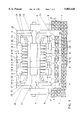
- FIG. 2 shows a first cross-section through the turbine-driven generator according to FIG. 1 at the level between two coolers along the line AA;
- FIG. 3 shows a second cross-section through the turbine-driven generator according to FIG. 1 at the level of the cooler along the line BB;
- FIG. 4 shows a horizontal section through the turbine-driven generator according to FIG. 1 below the stator laminated core along the line CC;
- FIG. 5 shows a greatly simplified longitudinal section through a machine group comprising a thermal and an electric machine.
- the air-cooled turbine-driven generator represented in FIG. 1 has a machine housing 1 which encloses the stator laminated core comprising component laminated cores 2. Radial ventilation ducts 3 are provided between the individual component laminated cores 2 in the stator laminated core. A rotor 4 is supported in pedestal bearings 5, 6 which are mounted on the foundation 7 by means of tie-bolts 8. The machine housing 1 is likewise mounted on the foundation 7 by means of tie-bolts 9 (compare FIGS. 2 and 3).
- the foundation 7 has a foundation pit 10 which extends axially over the entire length of the machine housing 1 and occupies virtually the entire width of the housing 1.
- a cooling arrangement of the machine is arranged in this foundation pit 10. It is of modular construction and comprises in the case of the example six mutually identical coolers 11. They are arranged independently of one another in the foundation pit. In this arrangement, the inlet openings of the coolers 11 are connected to outflow spaces 36 of fans 12 arranged on both sides of the rotor 4, and the outlet openings of the coolers 11 open into a compensating space 13.
- the cooling gas flowing through the coolers 11 is represented by means of arrows, hot gas flowing in being denoted by 18 and cold gas flowing out by 19. All further arrows not denoted in more detail show the cooling circuit or the cooling gas.
- the cooling circuit is marked by arrows only in one machine half, since the machine is of symmetrical construction with respect to cooling.
- the cooling principle is a so-called reverse flow cooling in which the hot gas 18 is fed to the coolers 11 by means of fans 12. Cold gas 19 then flows from the coolers 11 through the compensating space 13 into the rear of the machine, that is to say the space between the machine housing 1 and the stator laminated core constructed from component laminated cores 2.
- Hot-gas and cold-gas chambers 15, 17, 14 and 16 are formed in the rear of the housing by housing ribs 22 and radial and axial partitions 23 or 24.
- the cooling-gas flow is distributed between the cold-gas chambers 14 and 16, subflows being formed.
- a first subflow flows between baffles 26 and an inner fairing 21 directly to the rotor 4
- a second flows through the winding overhang 27 into the machine air gap 25
- a third cooling-gas flow passes through the cold-gas chamber 16 and ventilation ducts 3 into the air gap 25. From the latter, the cooling-gas flow is extracted by the fans 12 through ventilation ducts 3 and the hot-gas chambers 15 and 17 between the inner fairing 21 and an outer fairing 20 and subsequently pressed to the coolers 11 in the foundation pit 10.
- FIG. 2 shows the arrangement of the machine on its foundation 7 in a cross-section according to the line AA in FIG. 1.
- 32 denotes guide rails on which the coolers rest.
- FIG. 3 shows the coolers 11 arranged in recesses 29a, 29b of the side walls 28 of the foundation 7.
- the recesses 29a, 29b have the same cross-sectional form of the coolers 11, the latter being held in the recesses perpendicular to the machine axis.
- the cooler 11 is pushed in the manner of a drawer through the first recess 29a on the withdrawal side in the direction of displacement 31 into the space below the machine housing 1, in such a way that the connecting fittings 30 arranged on it project into the second recess 29b.
- the cooler 11 is connected to further devices of a cooling system, which is not shown.
- the coolers 11 and the guide rails 32 divide the space under the machine housing 1 into the compensating space 13 and the foundation pit 10 (compare FIG. 2 and FIG. 3).
- This design is advantageous, in particular, if a cooler has failed.
- hot cooling gas can be prevented from passing into the cold-gas chambers.
- the machine can then continue to be operated at lower power using the remaining (intact) coolers in conjunction with the axial compensating space 13.
- the coolers 11 are represented in longitudinal sections through the foundation 7 in FIG. 4.
- accommodating the coolers 11 in the foundation pit means that use is made of the entire space below the active part of the machine, that is to say the part of the machine between the winding overhang 27, including the latter.
- the transport profile of the machine is not enlarged thereby, which is of decisive importance for transport by rail. It is possible in this way to increase the cooling surface by 50% and more in comparison with the prior art.
- the invention is particularly suitable for gas plants and combined plants in which the thermal machine(s) 33, FIG. 5 is or are set up on a plate-type foundation 34.
- the foundation level 35 of the turbine-driven generator is higher by 1000 and more millimeters than the plate-type foundation level 33 of the thermal machine(s) 33.
- the housing 1 of the machine is mounted, with the interposition of a foundation 7, on the actual plate-type foundation 34, the interior of the foundation 7 serves as foundation pit 10. It is then very easy for the coolers 11 to be moved out laterally for purposes of installation, servicing and repair, because the highest possible degree of accessibility is ensured.
- the invention was explained above with the aid of a gas-cooled machine having three hot-gas chambers and four cold-gas chambers, the latter being fed with cooling gas from six coolers.
- the invention can also be realized in the case of machines having a different number of hot-gas chambers, cold-gas chambers and coolers. If appropriate, all that is then required is for the cooling gas to be guided in a changed way by means of housing ribs and radial and axial partitions in the rear of the machine.
Abstract
Description
Claims (4)
Applications Claiming Priority (2)
| Application Number | Priority Date | Filing Date | Title |
|---|---|---|---|
| DE19645272.4 | 1996-11-02 | ||
| DE19645272A DE19645272A1 (en) | 1996-11-02 | 1996-11-02 | Gas-cooled electrical machine |
Publications (1)
| Publication Number | Publication Date |
|---|---|
| US5883448A true US5883448A (en) | 1999-03-16 |
Family
ID=7810519
Family Applications (1)
| Application Number | Title | Priority Date | Filing Date |
|---|---|---|---|
| US08/962,687 Expired - Fee Related US5883448A (en) | 1996-11-02 | 1997-11-03 | Gas-cooled electric machine |
Country Status (9)
| Country | Link |
|---|---|
| US (1) | US5883448A (en) |
| EP (1) | EP0840426A1 (en) |
| JP (1) | JPH10146022A (en) |
| KR (1) | KR19980041977A (en) |
| CN (1) | CN1184363A (en) |
| BR (1) | BR9705202A (en) |
| CZ (1) | CZ347297A3 (en) |
| DE (1) | DE19645272A1 (en) |
| HU (1) | HUP9701781A2 (en) |
Cited By (25)
| Publication number | Priority date | Publication date | Assignee | Title |
|---|---|---|---|---|
| US6037683A (en) * | 1997-11-18 | 2000-03-14 | Abb Patent Gmbh | Gas-cooled turbogenerator |
| US6124653A (en) * | 1998-04-23 | 2000-09-26 | Asea Brown Boveri Ag | Overflow ducts of a generator with direct induced-draft cooling |
| US6124567A (en) * | 1998-12-10 | 2000-09-26 | Illinois Tool Works Inc. | Die cast housing for welding machine generator |
| US6201323B1 (en) * | 1998-11-25 | 2001-03-13 | Hitachi, Ltd. | Rotating machine |
| US6211586B1 (en) | 1996-12-19 | 2001-04-03 | Asea Brown Boveri Ag | Gas-cooled electrical machine |
| US6232682B1 (en) | 1999-11-10 | 2001-05-15 | General Electric Co. | Gas cooled solid conductor series loop cap assembly |
| US6239522B1 (en) * | 1998-12-03 | 2001-05-29 | Asea Brown Boveri Ag | Generator cooling with mixing downstream of the cooler |
| US6268668B1 (en) | 2000-01-03 | 2001-07-31 | General Electric Co. | Gas cooled generator stator structure and method for impingement cooling of generator stator coil |
| US6392320B1 (en) * | 1998-12-03 | 2002-05-21 | Alstom | Gas-cooled electrical machine having an axial fan |
| US20040000820A1 (en) * | 2002-06-13 | 2004-01-01 | Cromas Joseph Charles | Automotive generator |
| WO2004017494A1 (en) * | 2002-08-16 | 2004-02-26 | Alstom Technology Ltd | Dynamoelectric generator |
| US6707179B2 (en) | 2001-07-20 | 2004-03-16 | Siemens Westinghouse Power Corporation | Protected seal and related methods for sealing fluid in power generation system |
| US6724107B1 (en) | 1999-09-03 | 2004-04-20 | Hitachi, Ltd. | Dynamo-electric machine |
| US6737768B2 (en) * | 2000-03-31 | 2004-05-18 | Hitachi, Ltd. | Rotating electric machine |
| US20050023909A1 (en) * | 2002-06-13 | 2005-02-03 | Cromas Joseph Charles | Automotive generator |
| US20050172651A1 (en) * | 2002-08-16 | 2005-08-11 | Alstom Technology Ltd | Dynamoelectrical generator |
| EP1583203A3 (en) * | 2004-03-31 | 2006-01-11 | ALSTOM Technology Ltd | Turbogenerator |
| US20070194639A1 (en) * | 2006-02-21 | 2007-08-23 | Honeywell International, Inc. | High power generator with enhanced stator heat removal |
| US20080238224A1 (en) * | 2004-09-09 | 2008-10-02 | Siemens Aktiengesellschaft | Electrical Appliance |
| US20100102655A1 (en) * | 2008-10-28 | 2010-04-29 | Uffe Eriksen | Arrangement for cooling of an electrical machine |
| US20100186307A1 (en) * | 2008-12-18 | 2010-07-29 | Alstom Technology Ltd | Acoustic alternator delimitation |
| US20120049669A1 (en) * | 2010-08-25 | 2012-03-01 | Ruldolph Garriga | Systems and methods for fluid distribution for cooling and lubrication of electric machines |
| US20120049668A1 (en) * | 2010-08-25 | 2012-03-01 | Ruldolph Garriga | Systems and methods for cooling and lubrication of electric machines |
| US20180309332A1 (en) * | 2017-04-24 | 2018-10-25 | Rolls-Royce Plc | Electrical Machine Apparatus |
| US11859631B2 (en) * | 2020-02-26 | 2024-01-02 | Siemens Energy Global GmbH & Co. KG | Rotor structure for a turbomachine with venting/sealing arrangement in tie bolt |
Families Citing this family (7)
| Publication number | Priority date | Publication date | Assignee | Title |
|---|---|---|---|---|
| DE19820111A1 (en) * | 1998-05-06 | 1999-11-11 | Asea Brown Boveri | Generator that can be driven according to suction cooling principle |
| DE19931664A1 (en) * | 1999-07-08 | 2001-01-11 | Asea Brown Boveri | Adjustable cooling device for turbogenerators |
| DE19950418A1 (en) * | 1999-10-20 | 2001-04-26 | Abb Patent Gmbh | Air cooling turbogenerator of electric machine, invovles applying cold air in duct arranged in air gap and guiding over cooling slits |
| DE102006002173A1 (en) | 2006-01-16 | 2007-08-09 | Alstom Technology Ltd. | Gas-cooled electric machine, in particular generator |
| ATE504108T1 (en) * | 2008-02-27 | 2011-04-15 | Alstom Technology Ltd | FAN COOLING OF AN ELECTRIC DRIVE |
| DE102014223527A1 (en) * | 2014-11-18 | 2016-06-02 | Siemens Aktiengesellschaft | Cooling of an axial end portion of a stator of a rotating electrical machine |
| CN108365708A (en) * | 2018-04-11 | 2018-08-03 | 哈尔滨电机厂有限责任公司 | A kind of host cushion block and ventilated box integrated technique |
Citations (10)
| Publication number | Priority date | Publication date | Assignee | Title |
|---|---|---|---|---|
| US953574A (en) * | 1909-03-27 | 1910-03-29 | Bbc Brown Boveri & Cie | Cooling of inclosed dynamo-electric machinery. |
| GB214935A (en) * | 1922-10-24 | 1924-04-24 | British Thomson Houston Co Ltd | Improvements in and relating to cooling and ventilating systems for dynamo electric machines |
| GB297467A (en) * | 1927-09-23 | 1929-11-28 | Gen Electric | Improvements in or relating to means for cooling of dynamo electric machines |
| DE720154C (en) * | 1936-03-01 | 1942-04-25 | Siemens Ag | Ventilation arrangement for electrical machines, especially turbo-generators |
| DE868176C (en) * | 1950-08-10 | 1953-02-23 | Siemens Ag | Cooling arrangement for gas-filled electrical machines |
| US2695368A (en) * | 1953-01-27 | 1954-11-23 | Gen Electric | Dynamoelectric machine stator winding with fluid-cooling passages in conductor bars |
| US2746269A (en) * | 1955-03-17 | 1956-05-22 | Trane Co | Plural stage refrigerating apparatus |
| DE4332304A1 (en) * | 1993-08-17 | 1995-02-23 | Abb Management Ag | Gas-cooled electrical machine |
| US5557153A (en) * | 1993-09-15 | 1996-09-17 | Abb Management Ag | Air-cooled rotating electrical machine |
| US5652469A (en) * | 1994-06-16 | 1997-07-29 | General Electric Company | Reverse flow ventilation system with stator core center discharge duct and/or end region cooling system |
Family Cites Families (2)
| Publication number | Priority date | Publication date | Assignee | Title |
|---|---|---|---|---|
| DE464492C (en) * | 1928-08-18 | Bbc Brown Boveri & Cie | Radiator consisting of several vertically or diagonally suspended parts for the circulating cooling air of electrical machines | |
| DE723640C (en) * | 1939-02-14 | 1942-08-07 | Aeg | Cooling device for recooled electrical machines of high performance with radially divided axial fans |
-
1996
- 1996-11-02 DE DE19645272A patent/DE19645272A1/en not_active Withdrawn
-
1997
- 1997-10-08 EP EP97810753A patent/EP0840426A1/en not_active Withdrawn
- 1997-10-29 KR KR1019970056018A patent/KR19980041977A/en not_active Application Discontinuation
- 1997-10-30 HU HU9701781A patent/HUP9701781A2/en unknown
- 1997-10-30 JP JP9298825A patent/JPH10146022A/en active Pending
- 1997-10-31 BR BR9705202-7A patent/BR9705202A/en not_active IP Right Cessation
- 1997-10-31 CZ CZ973472A patent/CZ347297A3/en unknown
- 1997-11-01 CN CN97114174A patent/CN1184363A/en active Pending
- 1997-11-03 US US08/962,687 patent/US5883448A/en not_active Expired - Fee Related
Patent Citations (10)
| Publication number | Priority date | Publication date | Assignee | Title |
|---|---|---|---|---|
| US953574A (en) * | 1909-03-27 | 1910-03-29 | Bbc Brown Boveri & Cie | Cooling of inclosed dynamo-electric machinery. |
| GB214935A (en) * | 1922-10-24 | 1924-04-24 | British Thomson Houston Co Ltd | Improvements in and relating to cooling and ventilating systems for dynamo electric machines |
| GB297467A (en) * | 1927-09-23 | 1929-11-28 | Gen Electric | Improvements in or relating to means for cooling of dynamo electric machines |
| DE720154C (en) * | 1936-03-01 | 1942-04-25 | Siemens Ag | Ventilation arrangement for electrical machines, especially turbo-generators |
| DE868176C (en) * | 1950-08-10 | 1953-02-23 | Siemens Ag | Cooling arrangement for gas-filled electrical machines |
| US2695368A (en) * | 1953-01-27 | 1954-11-23 | Gen Electric | Dynamoelectric machine stator winding with fluid-cooling passages in conductor bars |
| US2746269A (en) * | 1955-03-17 | 1956-05-22 | Trane Co | Plural stage refrigerating apparatus |
| DE4332304A1 (en) * | 1993-08-17 | 1995-02-23 | Abb Management Ag | Gas-cooled electrical machine |
| US5557153A (en) * | 1993-09-15 | 1996-09-17 | Abb Management Ag | Air-cooled rotating electrical machine |
| US5652469A (en) * | 1994-06-16 | 1997-07-29 | General Electric Company | Reverse flow ventilation system with stator core center discharge duct and/or end region cooling system |
Non-Patent Citations (2)
| Title |
|---|
| "Development of Large Air Cooled Generators, etc.", Ruelle, et al., Cigre 1992 Session, p. 1-6. |
| Development of Large Air Cooled Generators, etc. , Ruelle, et al., Cigre 1992 Session, p. 1 6. * |
Cited By (41)
| Publication number | Priority date | Publication date | Assignee | Title |
|---|---|---|---|---|
| US6211586B1 (en) | 1996-12-19 | 2001-04-03 | Asea Brown Boveri Ag | Gas-cooled electrical machine |
| US6037683A (en) * | 1997-11-18 | 2000-03-14 | Abb Patent Gmbh | Gas-cooled turbogenerator |
| US6124653A (en) * | 1998-04-23 | 2000-09-26 | Asea Brown Boveri Ag | Overflow ducts of a generator with direct induced-draft cooling |
| US6359351B1 (en) * | 1998-11-25 | 2002-03-19 | Hitachi, Ltd. | Rotating machine |
| US6201323B1 (en) * | 1998-11-25 | 2001-03-13 | Hitachi, Ltd. | Rotating machine |
| US6239522B1 (en) * | 1998-12-03 | 2001-05-29 | Asea Brown Boveri Ag | Generator cooling with mixing downstream of the cooler |
| US6392320B1 (en) * | 1998-12-03 | 2002-05-21 | Alstom | Gas-cooled electrical machine having an axial fan |
| US6124567A (en) * | 1998-12-10 | 2000-09-26 | Illinois Tool Works Inc. | Die cast housing for welding machine generator |
| US6724107B1 (en) | 1999-09-03 | 2004-04-20 | Hitachi, Ltd. | Dynamo-electric machine |
| US6936939B2 (en) | 1999-09-03 | 2005-08-30 | Hitachi, Ltd. | Rotating electric machine and cooling method thereof |
| US6232682B1 (en) | 1999-11-10 | 2001-05-15 | General Electric Co. | Gas cooled solid conductor series loop cap assembly |
| US6268668B1 (en) | 2000-01-03 | 2001-07-31 | General Electric Co. | Gas cooled generator stator structure and method for impingement cooling of generator stator coil |
| US6737768B2 (en) * | 2000-03-31 | 2004-05-18 | Hitachi, Ltd. | Rotating electric machine |
| US6707179B2 (en) | 2001-07-20 | 2004-03-16 | Siemens Westinghouse Power Corporation | Protected seal and related methods for sealing fluid in power generation system |
| US20050023909A1 (en) * | 2002-06-13 | 2005-02-03 | Cromas Joseph Charles | Automotive generator |
| US20040000820A1 (en) * | 2002-06-13 | 2004-01-01 | Cromas Joseph Charles | Automotive generator |
| WO2004017494A1 (en) * | 2002-08-16 | 2004-02-26 | Alstom Technology Ltd | Dynamoelectric generator |
| US20050172651A1 (en) * | 2002-08-16 | 2005-08-11 | Alstom Technology Ltd | Dynamoelectrical generator |
| EP1583203A3 (en) * | 2004-03-31 | 2006-01-11 | ALSTOM Technology Ltd | Turbogenerator |
| US20080238224A1 (en) * | 2004-09-09 | 2008-10-02 | Siemens Aktiengesellschaft | Electrical Appliance |
| US7777374B2 (en) * | 2004-09-09 | 2010-08-17 | Siemens Aktiengesellschaft | Electrical appliance |
| US7439646B2 (en) * | 2006-02-21 | 2008-10-21 | Honeywell International, Inc. | High power generator with enhanced stator heat removal |
| US20070194639A1 (en) * | 2006-02-21 | 2007-08-23 | Honeywell International, Inc. | High power generator with enhanced stator heat removal |
| US8299663B2 (en) | 2008-10-28 | 2012-10-30 | Siemens Aktiengesellschaft | Arrangement for cooling of an electrical machine |
| US20100102655A1 (en) * | 2008-10-28 | 2010-04-29 | Uffe Eriksen | Arrangement for cooling of an electrical machine |
| US8400034B2 (en) * | 2008-12-18 | 2013-03-19 | Alstom Technology Ltd | Acoustic alternator delimitation |
| CN101867258B (en) * | 2008-12-18 | 2014-07-09 | 阿尔斯通技术有限公司 | Acoustic alternator delimitation |
| US20100186307A1 (en) * | 2008-12-18 | 2010-07-29 | Alstom Technology Ltd | Acoustic alternator delimitation |
| CN101867258A (en) * | 2008-12-18 | 2010-10-20 | 阿尔斯通技术有限公司 | Acoustic alternator delimitation |
| US20120049668A1 (en) * | 2010-08-25 | 2012-03-01 | Ruldolph Garriga | Systems and methods for cooling and lubrication of electric machines |
| US20120049665A1 (en) * | 2010-08-25 | 2012-03-01 | Rudolph Garriga | Systems and methods for fluid cooling of electric machines |
| US8410647B2 (en) * | 2010-08-25 | 2013-04-02 | Clean Wave Technologies Inc. | Systems and methods for fluid distribution for cooling and lubrication of electric machines |
| US8427019B2 (en) * | 2010-08-25 | 2013-04-23 | Clean Wave Technologies, Inc. | Systems and methods for cooling and lubrication of electric machines |
| US8432076B2 (en) | 2010-08-25 | 2013-04-30 | Clean Wave Technologies, Inc. | Systems and methods for providing fluid for internal cooling and lubrication of electric machines |
| US8482168B2 (en) * | 2010-08-25 | 2013-07-09 | Clean Wave Technologies, Inc. | Systems and methods for fluid cooling of electric machines |
| US20120049669A1 (en) * | 2010-08-25 | 2012-03-01 | Ruldolph Garriga | Systems and methods for fluid distribution for cooling and lubrication of electric machines |
| US8872400B2 (en) | 2010-08-25 | 2014-10-28 | Clean Wave Technologies, Inc. | Systems and methods for regulating fluid flow for internal cooling and lubrication of electric machines |
| TWI484732B (en) * | 2010-08-25 | 2015-05-11 | Clean Wave Technologies Inc | Systems and methods for fluid cooling of electric machines |
| US10050495B2 (en) | 2010-08-25 | 2018-08-14 | Clean Wave Technologies, Inc. | Systems and methods for regulating fluid flow for internal cooling and lubrication of electric machines |
| US20180309332A1 (en) * | 2017-04-24 | 2018-10-25 | Rolls-Royce Plc | Electrical Machine Apparatus |
| US11859631B2 (en) * | 2020-02-26 | 2024-01-02 | Siemens Energy Global GmbH & Co. KG | Rotor structure for a turbomachine with venting/sealing arrangement in tie bolt |
Also Published As
| Publication number | Publication date |
|---|---|
| EP0840426A1 (en) | 1998-05-06 |
| JPH10146022A (en) | 1998-05-29 |
| DE19645272A1 (en) | 1998-05-07 |
| HUP9701781A2 (en) | 1998-06-29 |
| BR9705202A (en) | 1999-09-21 |
| CN1184363A (en) | 1998-06-10 |
| KR19980041977A (en) | 1998-08-17 |
| CZ347297A3 (en) | 1998-05-13 |
| HU9701781D0 (en) | 1997-12-29 |
Similar Documents
| Publication | Publication Date | Title |
|---|---|---|
| US5883448A (en) | Gas-cooled electric machine | |
| US4352034A (en) | Stator core with axial and radial cooling for dynamoelectric machines wth air-gap stator windings | |
| US6097116A (en) | Turbo-generator | |
| US9225224B2 (en) | Dynamoelectric machine having air/liquid cooling | |
| US5652469A (en) | Reverse flow ventilation system with stator core center discharge duct and/or end region cooling system | |
| US3597645A (en) | Liquid cooling system for stacks of stator laminations of electrical machinery | |
| US2618756A (en) | Liquid cooled electrical machine | |
| US5796191A (en) | Bulb-type generator | |
| EP1005139B1 (en) | Cooling device for an electric rotating machine | |
| US6037683A (en) | Gas-cooled turbogenerator | |
| US4876470A (en) | Gas-cooled electric machine | |
| US7141898B2 (en) | Gas-cooled generator | |
| US5602435A (en) | Gas-cooled electrical machine | |
| US20100176670A1 (en) | Machine cooling scheme | |
| US4546279A (en) | Dynamoelectric machine with rotor ventilation system including exhaust coolant gas diffuser and noise baffle | |
| US7342345B2 (en) | Paddled rotor spaceblocks | |
| EP3968501A1 (en) | Stator block, stator assembly, and cooling system for stator assembly | |
| KR20100044127A (en) | Heat transfer enhancement of dynamoelectric machine rotors | |
| JPS5840897B2 (en) | backflow cooled electric machine | |
| US7190094B2 (en) | Multi-path cooling of a turbo-generator rotor winding | |
| CN107750414B (en) | Electric machine | |
| US3441758A (en) | Dynamoelectric machine cooling arrangement | |
| US3908140A (en) | Liquid-cooled rotor for dynamoelectric machines | |
| US4163163A (en) | Non-salient pole synchronous electric generator | |
| US4100439A (en) | Apparatus for cooling the end zones of the lamination stacks of electric machines |
Legal Events
| Date | Code | Title | Description |
|---|---|---|---|
| AS | Assignment |
Owner name: ASEA BROWN BOVERI AG, SWITZERLAND Free format text: ASSIGNMENT OF ASSIGNORS INTEREST;ASSIGNOR:ZIMMERMANN, HANS;REEL/FRAME:009625/0867 Effective date: 19971007 |
|
| FEPP | Fee payment procedure |
Free format text: PAYOR NUMBER ASSIGNED (ORIGINAL EVENT CODE: ASPN); ENTITY STATUS OF PATENT OWNER: LARGE ENTITY |
|
| AS | Assignment |
Owner name: ALSTOM, FRANCE Free format text: ASSIGNMENT OF ASSIGNORS INTEREST;ASSIGNOR:ASEA BROWN BOVERI AG;REEL/FRAME:012287/0714 Effective date: 20011109 |
|
| FPAY | Fee payment |
Year of fee payment: 4 |
|
| REMI | Maintenance fee reminder mailed | ||
| LAPS | Lapse for failure to pay maintenance fees | ||
| STCH | Information on status: patent discontinuation |
Free format text: PATENT EXPIRED DUE TO NONPAYMENT OF MAINTENANCE FEES UNDER 37 CFR 1.362 |
|
| FP | Lapsed due to failure to pay maintenance fee |
Effective date: 20070316 |