US5865335A - Easy-open closure - Google Patents
Easy-open closure Download PDFInfo
- Publication number
- US5865335A US5865335A US08/978,556 US97855697A US5865335A US 5865335 A US5865335 A US 5865335A US 97855697 A US97855697 A US 97855697A US 5865335 A US5865335 A US 5865335A
- Authority
- US
- United States
- Prior art keywords
- container
- closure
- central panel
- package
- peripheral portion
- Prior art date
- Legal status (The legal status is an assumption and is not a legal conclusion. Google has not performed a legal analysis and makes no representation as to the accuracy of the status listed.)
- Expired - Fee Related
Links
Images


Classifications
-
- B—PERFORMING OPERATIONS; TRANSPORTING
- B65—CONVEYING; PACKING; STORING; HANDLING THIN OR FILAMENTARY MATERIAL
- B65B—MACHINES, APPARATUS OR DEVICES FOR, OR METHODS OF, PACKAGING ARTICLES OR MATERIALS; UNPACKING
- B65B61/00—Auxiliary devices, not otherwise provided for, for operating on sheets, blanks, webs, binding material, containers or packages
- B65B61/02—Auxiliary devices, not otherwise provided for, for operating on sheets, blanks, webs, binding material, containers or packages for perforating, scoring, slitting, or applying code or date marks on material prior to packaging
-
- B—PERFORMING OPERATIONS; TRANSPORTING
- B65—CONVEYING; PACKING; STORING; HANDLING THIN OR FILAMENTARY MATERIAL
- B65D—CONTAINERS FOR STORAGE OR TRANSPORT OF ARTICLES OR MATERIALS, e.g. BAGS, BARRELS, BOTTLES, BOXES, CANS, CARTONS, CRATES, DRUMS, JARS, TANKS, HOPPERS, FORWARDING CONTAINERS; ACCESSORIES, CLOSURES, OR FITTINGS THEREFOR; PACKAGING ELEMENTS; PACKAGES
- B65D17/00—Rigid or semi-rigid containers specially constructed to be opened by cutting or piercing, or by tearing of frangible members or portions
- B65D17/28—Rigid or semi-rigid containers specially constructed to be opened by cutting or piercing, or by tearing of frangible members or portions at lines or points of weakness
- B65D17/401—Rigid or semi-rigid containers specially constructed to be opened by cutting or piercing, or by tearing of frangible members or portions at lines or points of weakness characterised by having the line of weakness provided in an end wall
- B65D17/4011—Rigid or semi-rigid containers specially constructed to be opened by cutting or piercing, or by tearing of frangible members or portions at lines or points of weakness characterised by having the line of weakness provided in an end wall for opening completely by means of a tearing tab
-
- B—PERFORMING OPERATIONS; TRANSPORTING
- B65—CONVEYING; PACKING; STORING; HANDLING THIN OR FILAMENTARY MATERIAL
- B65D—CONTAINERS FOR STORAGE OR TRANSPORT OF ARTICLES OR MATERIALS, e.g. BAGS, BARRELS, BOTTLES, BOXES, CANS, CARTONS, CRATES, DRUMS, JARS, TANKS, HOPPERS, FORWARDING CONTAINERS; ACCESSORIES, CLOSURES, OR FITTINGS THEREFOR; PACKAGING ELEMENTS; PACKAGES
- B65D17/00—Rigid or semi-rigid containers specially constructed to be opened by cutting or piercing, or by tearing of frangible members or portions
- B65D17/28—Rigid or semi-rigid containers specially constructed to be opened by cutting or piercing, or by tearing of frangible members or portions at lines or points of weakness
- B65D17/402—Rigid or semi-rigid containers specially constructed to be opened by cutting or piercing, or by tearing of frangible members or portions at lines or points of weakness characterised by having the line of weakness provided in the side wall
-
- B—PERFORMING OPERATIONS; TRANSPORTING
- B65—CONVEYING; PACKING; STORING; HANDLING THIN OR FILAMENTARY MATERIAL
- B65D—CONTAINERS FOR STORAGE OR TRANSPORT OF ARTICLES OR MATERIALS, e.g. BAGS, BARRELS, BOTTLES, BOXES, CANS, CARTONS, CRATES, DRUMS, JARS, TANKS, HOPPERS, FORWARDING CONTAINERS; ACCESSORIES, CLOSURES, OR FITTINGS THEREFOR; PACKAGING ELEMENTS; PACKAGES
- B65D3/00—Rigid or semi-rigid containers having bodies or peripheral walls of curved or partially-curved cross-section made by winding or bending paper without folding along defined lines
- B65D3/26—Opening arrangements or devices incorporated in, or attached to, containers
- B65D3/261—Opening arrangements or devices incorporated in, or attached to, containers the opening arrangement being located in the container side wall
- B65D3/262—Opening arrangements or devices incorporated in, or attached to, containers the opening arrangement being located in the container side wall forming a circumferential line of weakness
- B65D3/263—Opening arrangements or devices incorporated in, or attached to, containers the opening arrangement being located in the container side wall forming a circumferential line of weakness and having an attached or applied tearing or reinforcing element
-
- B—PERFORMING OPERATIONS; TRANSPORTING
- B65—CONVEYING; PACKING; STORING; HANDLING THIN OR FILAMENTARY MATERIAL
- B65D—CONTAINERS FOR STORAGE OR TRANSPORT OF ARTICLES OR MATERIALS, e.g. BAGS, BARRELS, BOTTLES, BOXES, CANS, CARTONS, CRATES, DRUMS, JARS, TANKS, HOPPERS, FORWARDING CONTAINERS; ACCESSORIES, CLOSURES, OR FITTINGS THEREFOR; PACKAGING ELEMENTS; PACKAGES
- B65D55/00—Accessories for container closures not otherwise provided for
- B65D55/02—Locking devices; Means for discouraging or indicating unauthorised opening or removal of closure
- B65D55/06—Deformable or tearable wires, strings, or strips; Use of seals, e.g. destructible locking pins
- B65D55/08—Annular elements encircling container necks
- B65D55/0863—Plastic snap-on cap-like collars having frangible parts
-
- B—PERFORMING OPERATIONS; TRANSPORTING
- B65—CONVEYING; PACKING; STORING; HANDLING THIN OR FILAMENTARY MATERIAL
- B65D—CONTAINERS FOR STORAGE OR TRANSPORT OF ARTICLES OR MATERIALS, e.g. BAGS, BARRELS, BOTTLES, BOXES, CANS, CARTONS, CRATES, DRUMS, JARS, TANKS, HOPPERS, FORWARDING CONTAINERS; ACCESSORIES, CLOSURES, OR FITTINGS THEREFOR; PACKAGING ELEMENTS; PACKAGES
- B65D75/00—Packages comprising articles or materials partially or wholly enclosed in strips, sheets, blanks, tubes, or webs of flexible sheet material, e.g. in folded wrappers
- B65D75/52—Details
- B65D75/58—Opening or contents-removing devices added or incorporated during package manufacture
- B65D75/5827—Tear-lines provided in a wall portion
- B65D75/5833—Tear-lines provided in a wall portion for tearing out a portion of the wall
- B65D75/5844—Tear-lines provided in a wall portion for tearing out a portion of the wall the portion of the wall being a narrow strip, e.g. between lines of weakness
-
- B—PERFORMING OPERATIONS; TRANSPORTING
- B29—WORKING OF PLASTICS; WORKING OF SUBSTANCES IN A PLASTIC STATE IN GENERAL
- B29C—SHAPING OR JOINING OF PLASTICS; SHAPING OF MATERIAL IN A PLASTIC STATE, NOT OTHERWISE PROVIDED FOR; AFTER-TREATMENT OF THE SHAPED PRODUCTS, e.g. REPAIRING
- B29C2793/00—Shaping techniques involving a cutting or machining operation
- B29C2793/0054—Shaping techniques involving a cutting or machining operation partially cutting through the material
-
- B—PERFORMING OPERATIONS; TRANSPORTING
- B29—WORKING OF PLASTICS; WORKING OF SUBSTANCES IN A PLASTIC STATE IN GENERAL
- B29C—SHAPING OR JOINING OF PLASTICS; SHAPING OF MATERIAL IN A PLASTIC STATE, NOT OTHERWISE PROVIDED FOR; AFTER-TREATMENT OF THE SHAPED PRODUCTS, e.g. REPAIRING
- B29C49/00—Blow-moulding, i.e. blowing a preform or parison to a desired shape within a mould; Apparatus therefor
- B29C49/22—Blow-moulding, i.e. blowing a preform or parison to a desired shape within a mould; Apparatus therefor using multilayered preforms or parisons
-
- B—PERFORMING OPERATIONS; TRANSPORTING
- B65—CONVEYING; PACKING; STORING; HANDLING THIN OR FILAMENTARY MATERIAL
- B65D—CONTAINERS FOR STORAGE OR TRANSPORT OF ARTICLES OR MATERIALS, e.g. BAGS, BARRELS, BOTTLES, BOXES, CANS, CARTONS, CRATES, DRUMS, JARS, TANKS, HOPPERS, FORWARDING CONTAINERS; ACCESSORIES, CLOSURES, OR FITTINGS THEREFOR; PACKAGING ELEMENTS; PACKAGES
- B65D2543/00—Lids or covers essentially for box-like containers
- B65D2543/00009—Details of lids or covers for rigid or semi-rigid containers
- B65D2543/00018—Overall construction of the lid
- B65D2543/00231—Overall construction of the lid made of several pieces
-
- B—PERFORMING OPERATIONS; TRANSPORTING
- B65—CONVEYING; PACKING; STORING; HANDLING THIN OR FILAMENTARY MATERIAL
- B65D—CONTAINERS FOR STORAGE OR TRANSPORT OF ARTICLES OR MATERIALS, e.g. BAGS, BARRELS, BOTTLES, BOXES, CANS, CARTONS, CRATES, DRUMS, JARS, TANKS, HOPPERS, FORWARDING CONTAINERS; ACCESSORIES, CLOSURES, OR FITTINGS THEREFOR; PACKAGING ELEMENTS; PACKAGES
- B65D2543/00—Lids or covers essentially for box-like containers
- B65D2543/00009—Details of lids or covers for rigid or semi-rigid containers
- B65D2543/00425—Lids or covers welded or adhered to the container
-
- B—PERFORMING OPERATIONS; TRANSPORTING
- B65—CONVEYING; PACKING; STORING; HANDLING THIN OR FILAMENTARY MATERIAL
- B65D—CONTAINERS FOR STORAGE OR TRANSPORT OF ARTICLES OR MATERIALS, e.g. BAGS, BARRELS, BOTTLES, BOXES, CANS, CARTONS, CRATES, DRUMS, JARS, TANKS, HOPPERS, FORWARDING CONTAINERS; ACCESSORIES, CLOSURES, OR FITTINGS THEREFOR; PACKAGING ELEMENTS; PACKAGES
- B65D2543/00—Lids or covers essentially for box-like containers
- B65D2543/00009—Details of lids or covers for rigid or semi-rigid containers
- B65D2543/00953—Sealing means
- B65D2543/00962—Sealing means inserted
- B65D2543/00972—Collars or rings
Definitions
- This invention relates to an easily opened closure suitable for use with a container which includes a layer of plastic.
- the closure may be of a multi-layer construction or may include a layer of barrier material. If an all-plastic closure is used with an all-plastic container, the container and closure assembly is especially suitable for microwaving.
- Microwavable containers are growing in popularity because they not only replace the storage function of the traditional can, but also enable the consumer to heat the contents in the container and to eat from the container.
- closures for microwavable containers generally included both a double seamed metal lid and a plastic overcap.
- the metal lid is double seamed onto the all-plastic container and has a score line in the metal lid.
- the consumer has to pull hard enough to break the metal score line and in doing so often splatters the food from the container.
- a residual rim of metal remains affixed to the top edge of the container after opening and removing the lid.
- the overcap is then snapped over the remaining rim and the container and overcap are placed in the microwave.
- the residual metal rim of the prior art container is undesirable because it has a sharp edge, making it prone to cut the fingers of those using the containers, especially children for whom the microwavable containers are particularly convenient.
- the prior art closure system also requires a large number of consumer steps for using the container: removing the overcap, opening the metal lid, replacing the overcap, placing the container in the microwave oven, heating the container and contents in the microwave oven, and removing the cap to gain access to the food.
- the overcap of the prior art has a number of characteristics necessary so that it can be used with a microwavable container.
- the center panel of the overcap is raised well above the top of the metal lid. A number of holes are punched in the center of the lid, and the overcap is sized so that it fits tightly with the outside of the container.
- microwave oven heats food in containers.
- the food is generally filled to the top of a microwavable container, making the raised overcap necessary to accommodate expansion of the food caused by steam bubbles.
- the holes in the lid allow for steam venting.
- Microwave heating causes explosive boiling in the food which creates splattering and can be so violent as to physically move the container. This is a type of localized superheating which does not occur in conventional cooking where heating is by conduction.
- the conventional stovetop cooking causes a more uniform, gentle heating which is unlikely to produce explosions.
- the overcap of the prior art must be tight-fitting to reduce the likelihood of explosions causing it to blow off of the container. However, this also makes removal of the lid more difficult, especially for elderly persons and young children.
- the container may be of a bowl shape, such as shown in the detailed embodiments herein, or of any other suitable shape, for example, a tapered cylinder.
- This invention is embodied in an easy-open closure which can be affixed to a container which is suitable for any number of food packaging applications, such as shelf stable, frozen, retortable or microwave. If the closure and container are all-plastic, as discussed relating to the following embodiments, the package is ideal for microwave applications. These embodiments may have to be modified somewhat for some of the other applications.
- the closure can be left in position to prevent splattering when the container and contents are heated. This eliminates the need for the overcap used in the prior art microwavable packages.
- a first embodiment utilizes a central panel and a ring which surrounds the peripheral edge of the central panel and the container sidewall.
- a tear strip is positioned within the ring.
- the central panel is recessed and fits loosely within the mouth of the container.
- a second embodiment uses a unitary plastic closure which includes a central portion that covers the opening of the container and a ring portion that is affixed to the container sidewall.
- a tear-strip forms a complete circle within the closure inwardly from the peripheral edge of the lid. The lid is recessed and fits loosely within the container.
- the closure of this invention remains on the container and serves to prevent splattering during heating.
- the tear-strip allows one closure to replace both the overcap and the metal seamed lid of the prior art.
- a third embodiment includes a central panel and a ring which surrounds the peripheral edge of the central panel and the container sidewall, and is secured to both.
- the central panel includes a full panel easy open end to provide access to the contents of the container.
- the embodiments of the closure described herein may be sized to fit loosely within the mouth of the container.
- the closure is free to bob up and down during heating in the microwave.
- the closure releases steam easily around its periphery instead of through central holes as does the prior art overcap.
- the closure may be recessed to such an extent that upon opening the closure and the closure center panel remaining positioned on the container, the food touches the central panel or a downward extension of the panel.
- the extent of recess should be sufficiently large so that the food expansion will not push the lid completely out of the mouth of the container.
- This invention also reduces the number of steps required by the consumer.
- the consumer simply removes the tear-strip and places it in the microwave oven. After microwaving, the consumer removes the lid to eat the contents. Not only is this method more convenient for the consumer but also cleaner since it eliminates splattering when preparing the container for microwaving.
- FIG. 1 is a perspective view of a first embodiment of the container and closure that is the subject of this invention.
- FIG. 2 is a top view of the first embodiment of FIG. 1 with the tearing initiated.
- FIG. 3 is a cross-sectional view of the first embodiment along lines 3--3 of FIG. 2.
- FIG. 4 is a cross-sectional view of the first embodiment of the container and closure with the tearing portion removed, and the closure remaining in position on the container.
- FIG. 5 is a cross-sectional view of the first embodiment of the container and closure with the closure opened via the tearing portion, and the closure removed.
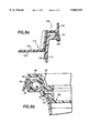
- FIG. 6a is a cross-sectional view showing the preferred tear-strip and sealing locations of the first embodiment.
- FIG. 6b is a cross-sectional view of the tear-strip and sealing locations of an alternative closure and container configuration of the first embodiment.
- FIG. 7 is a perspective view of a second embodiment of the container and closure that is the subject of this invention.
- FIG. 8a is a cross-sectional view of the preferred container and closure sealing configuration of the second embodiment.
- FIGS. 8b, 8c, 8d are cross-sectional views of alternative container and closure sealing configurations of the second embodiment.
- FIG. 9 is a cross-sectional view of the second embodiment of this invention taken across lines 9--9 of FIG. 7.
- FIG. 10 is a cross-sectional view of the second embodiment of this invention with the closure opened using the tearing portion, and with the closure in position on the container.
- FIG. 11 is a cross-sectional view of the second embodiment of this invention during the heating process, with food shown in the container.
- FIG. 12 is a perspective view of a third embodiment of the container and closure that is the subject of this invention.
- FIG. 13 is a cross-sectional view of the third embodiment taken along lines 13--13 of FIG. 12.
- FIG. 1 shows a food package, generally indicated as 10, which is the first embodiment of this invention.
- the package 10 includes a container 12, a closure 14 and a ring 18.
- the container 12 may be any container suitable for holding food, such as the bowl shaped container shown herein, a tapered cylinder, a tray, and may have a cross-section of any shape.
- the container 12 may be manufactured by any appropriate process, such as thermoforming, injection molding, or injection blow molding, and may be single layer or multi-layer.
- the container as described herein shall refer to a high barrier microwavable container, although it shall be understood that any suitable container may be used in this invention.
- the preferred container 12 is a multi-layer, high barrier, injection blow molded container consisting of five or more layers.
- the inner and outer layers of the container 12 are for structural integrity, and may be made of polypropylene (hereafter "PP") or preferably of a polypropylene/polyethylene blend (hereafter “PP-PE Blend”).
- the preferred structure also includes a central layer of oxygen barrier polymer, such as ethylene vinyl alcohol copolymer (hereafter “EVOH”) and two adhesive layers which are interposed between the central layer and the respective inner and outer layers.
- PP polypropylene
- PP-PE Blend polypropylene/polyethylene blend
- the adhesive layers may be of Admer, which is manufactured by Mitsui Petrochemical, Inc. and is a maleic anhydride grafted polypropylene copolymer. This structure can be given additional high barrier performance through the use of desiccants or oxygen scavengers in various layers as discussed in U.S. Pat. Nos. 4,407,897 and 4,425,410, herein incorporated by reference.
- the closure 14 may be formed in any of a variety of ways which produce a high barrier component.
- the closure may be thermoformed using a layer structure similar to the PP-PE Blend/adhesive/EVOH/adhesive/PP-PE Blend structure of the container.
- the closure structure may also include additional layers, such as a layer of regrind.
- the closure 14 may be insert injection molded around a disc of a barrier material which drops into open mold tools, as discussed in U.S. Pat. No. 4,149,838, herein incorporated by reference.
- the closure of FIG. 6a has thermoplastic material on both sides of the film, the thermoplastic can be injected on only one side of the film, since the thermoplastic can break through the film, either without or with a weakened area, as discussed in U.S. Pat. No. 4,230,659, herein incorporated by reference.
- the barrier material may be either a single layer of thermoplastic material or a multi-layer laminate sheet material.
- the insert is preferably a laminate which includes a barrier layer of saran, EVOH or aluminum foil.
- a preferred barrier laminate is a coextruded or laminate film with layers of saran, adhesive and polypropylene when polypropylene is the thermoplastic that is injection molded to form the closure. In such an injection molded closure 14, the barrier insert may be either on the top or the bottom of the closure 14.
- FIG. 6a shows an injection molded closure 14 with the barrier film 34 on the bottom of the closure 14 and the skirt 30 extending from the bottom of the film 34.
- the purpose of the closure skirt 30 is to maintain the closure in alignment with the inner surface 21 of the container sidewall 20 as the closure moves up and down within the container 12 during heating.
- the skirt 30 includes slits 31, as shown in FIG. 3. As the closure 14 rises upon heating in the microwave, the steam escapes through the slits 31.
- the peripheral portion 28 of the closure is an inverted U-shape with a gasket 32 positioned between the peripheral portion 28 and the container annular post 36, as shown in FIG. 6a.
- FIG. 6a shows that the container 12 includes a stop surface, here the upper surface of annular post 36 and/or of container sidewall step 21A, and that closure 14 has an engaging surface, here the undersurface of closure peripheral portion 28 and/or the undersurface at the periphery of the closure central panel portion where it joins upstanding wall 15.
- the container sidewall stop surface engages the closure engaging surface to prevent the closure from dropping or falling further into the container.
- the stop and engaging surfaces can be any suitable surfaces which function cooperatively as described.
- the gasket 32 is compressed between the closure 14 and the container 12 when the two are affixed together by the ring 18.
- One purpose of the gasket is to limit oxygen ingress. It is possible for oxygen to pervade the ring at the score lines 40 and 42 since approximately less than 0.010 inches of residual polypropylene remains.
- the gasket 32 as positioned in FIG. 6a prevents the ingress of oxygen from the score lines to the contents of the food.
- the gasket 32 which may be of styrene butadiene rubber, maintains the package's hermetic seal.
- a suitable material for the gasket is 480T, made by Dewey and Almy. Because this compound may adhere to the container when the package is opened and the closure removed, a thin layer of a lubricant 33, such as lecithin or another unsaturated fat or oil, is placed on the container 12 adjacent the opening 26 so that the gasket 32 mates with the lubricant.
- a lubricant 33 such as lecithin or another unsaturated fat or oil
- the closure may have an annular curl 52 aided by silicone grease to form the closure/container sealing interface 56, as shown in FIG. 6b.
- the closure of FIG. 6b is tightly sealed in the container opening 26 by compressive forces on the annular curl 52.
- the ring 18 is then welded to both the closure 14 and container 12.
- FIG. 6b also shows the dropped central panel 16b which contacts the food to maintain the closure in position during heating and food expansion.
- the ring 18 includes a tearing portion 38 which includes a tear strip 48 and two score lines, 40 and 42, which are positioned at the top of the ring.
- the ring 18 also includes an annular abrasion post 64 which allows the containers to be conveyed upside down without damaging the score lines 40 and 42.
- Ring 18 also includes a strengthening rib 66 to enable the tear strip 48 to be removed without breaking.
- the user pulls the ring starting tab 46 tearing through the sealing interface 56, then tears to the tear strip 48, pulling upward and around the container to completely remove the tear strip 48.
- the finishing point 50 of the tear strip is located on the outer score line 40 so that the panel is not pulled out during the removal of the tear strip.
- the cross pieces 58 are relatively cool while the closure central panel 16 is hot, so user grasps the cross pieces 58 to remove the closure.
- the cross pieces also provide a steady base for stacking one container onto the other.
- FIG. 6b Another method of interlocking members is shown in FIG. 6b, by means of interlocking lugs 72 on the container and a mating interlocking lug 74 on the closure. A variety of modifications of these designs will also prevent rotation between the container 12 and closure 14.
- Tabs 60 on the outside of the ring 18 provide a gripping surface for the spin welding machine to transmit force when spin welding the ring to the closure and container.
- Spin welding is especially suitable for the first embodiment shown because it allows the container 12 and closure 14 to remain stationary with regard to one another, so that the gasket remains compressed therebetween, providing a tightly sealed package.
- This first embodiment also isolates the food within the container from any particles generated by the spin welding process.
- the ring may also be welded to the container and central panel by other methods of welding known to the art, such as ultrasonic welding and RF sealing. Some modifications in the design may be required to practice these methods.
- FIGS. 3-5 show a cross-sectional view of the closed package 10 of the first embodiment.
- FIG. 4 shows a cross-sectional view of the first embodiment with the tear strip 48 removed and the closure central panel 16 still in place on the container 12.
- FIG. 5 shows a cross-sectional view of the first embodiment with the closure 14 opened and the central panel 16 removed.
- FIGS. 7 through 11 show a second embodiment of a microwavable package, generally referred to as 110.
- the second embodiment comprises a container 112 similar to the first embodiment and also a closure 114.
- the closure 114 may be injection molded with a barrier layer or thermoformed as discussed above.
- the closure 114 includes a central portion 116, surrounded by a peripheral lip 128 which is to be affixed to the container 112 at sealing interface 154, as shown in FIG. 8a.
- a separate ring member is not required in the second embodiment.
- FIGS. 8b through 8d show the examples of locations of the sealing interfaces 54 and 56, respectively, between the ring and container and the ring and the central panel.
- the tear strip 48 is located inwardly of the sealing interfaces.
- the sealing interfaces and the tear strip 48 may be positioned at other alternative locations as well, so long as the tear strip is positioned inwardly of the sealing interface 54 between the ring and the container.
- a gasket, 132b and 132d, respectively, as shown in FIGS. 8b and 8d, may be positioned between the container 110 and the closure 114 to reduce oxygen ingress.
- FIG. 7 shows a one piece closure with a starting tab 146 of an alternative design, which may also include an upwardly extending ledge 144 to protect the tab from damage during handling.
- the simultaneous molding of the starting tab 146 and ledge 144 requires a slit 184, as shown in FIG. 10, for removing mold steel.
- the cross piece 158 is of a different design than shown in the first embodiment, but still remains cool during heating to allow one to comfortably remove the closure.
- the preferred method of affixing the closure 114 of the second embodiment to the container 112 is to utilize ultrasonic welding to seal the closure 114 to the container 112 around the peripheral lip of the closure.
- 8b and 8d show versions of the second embodiment of this invention which are particularly suited for ultrasonic welding.
- Ultrasonic welding requires large equipment movable in the vertical direction to exert pressure in the vertical direction against two surfaces, here the peripheries of the closure and container, which can be placed on a horizontal mandrel.
- An alternative method of sealing the package of the second embodiment is to spin weld the closure 114 to the container 112.
- the closure preferably is injection molded on a barrier film 134 so that the scores on the resulting closure are on top of the barrier film.
- the barrier film 134 substantially covers the entire undersurface of closure 114.
- Collar 136 is injection molded onto the periphery of the underneath side of the closure.
- the collar 136 is preferably of a material with a similar structure to the container so that the spin welding seal will be stronger.
- the outer layer of the container is a PP/PE Blend, then the collar may be of a PP based homopolymer.
- RF sealing requires an electro-magnetically active sleeve, such as is commercially available under the tradename "EMAWELD".
- EMAWELD electro-magnetically active sleeve
- This sleeve 180 is placed around the opening end of the container with the closure then placed over the sleeve 180, as shown in FIG. 8c.
- the package assembly is then placed in a high intensity, high frequency electromagnetic field to RF seal the assembly.
- the sleeve 180 welds together the container and closure.
- FIG. 9 depicts the cross-section of the closed package that is the second embodiment of this, while FIG. 10 shows the second embodiment after the tear strip has been removed and the closure central portion remains in position on the container.
- FIG. 11 shows the second embodiment package during the heating process.
- the food A contacts the central portion 116 forcing the lid to move upwards as the food expands.
- the steam bubbles B are the result of superlocalized heating and do not occur in conventional heating.
- the apparent expansion of the food during heating is a result, to a small part, of the change in density of the food, but to a much greater extent is the result of the appearance of steam bubbles B.
- This expansion of the food pushes the lid up.
- the steam bubbles rise to the top and escape between the container and closure. Because of the loose fit and the relative shapes of the closure 114 within the container 112, steam can escape around the periphery of the closure 114.
- the food may also serve to restrain the closure from being ejected from the mouth of the container during the bumping which occurs during the microwave heating.
- the food may contact the central panel or a downward extension thereof in all of the embodiments described herein.
- the closure 114 must fit loosely within the container 112. Additionally, the container and closure must have mating surfaces, 160 and 162, respectively, such as shown in FIG. 10, that have angles to vertical that are substantially equal to one another. This allows the closure 114 to return to its position within the container without severe cocking, which would leave a large gap that would allow food to splatter during heating.
- the closure and container must also be designed to provide a certain amount of overlap between the container mating surfaces 160 and the closure mating surface 162, which move with respect to one another.
- This overlap should be approximately 0.2 inches or more, and is preferably greater than 0.3 inches and can be achieved partly or wholly by recessing the central panel into the container opening. This overlap can be approximated by measuring the recess of the central portion or central panel from an upper horizontal surface 159 of the closure 114.
- the closure includes a piston skirt such as shown in the first embodiment in FIG. 3, the recess of the central panel may be reduced because the closure mating surface 62 is extended by the closure skirt 30.
- the overlap of the closure mating surface 62 and the container mating surface 60 should be 0.2" or more, and it is preferably greater than 0.3".
- the piston skirt also minimizes food entrapment between the two mating surfaces. Such trapped food becomes baked on during heating, causing a negative consumer reaction.
- FIGS. 12 and 13 show a third embodiment of the microwavable package, generally identified as 210, that is the subject of this invention.
- the package 210 includes a container 212, a closure 214 and a ring 218.
- the container 212 includes a sidewall 220, a closed end, an end with an opening, and an outwardly extending flange 286.
- the closure 214 and ring 218 of the third embodiment are similar to those of the first embodiment except that the tearing portion is on the closure 214 and not on the ring 218.
- the closure which is a type of full panel easy-open end, has a tearing portion that comprises a circular score line 240 on the closure 214. Tearing is initiated by pulling on the starting tab 246 and pulling the central panel annular portion 242 and a portion of the barrier film 234 out of the package to reveal the contents of the package. The user then replaces the annular portion 242 and the barrier film 234 in the container during heating.
- container sidewall 220 has an inwardly angled portion 221 whose inner surface is a stop surface 221A, and that the skirt 300 of closure 214 has an engaging surface here shown as its bottom edge surface 322 which in this embodiment is disposed at an angle substantially equal to that of sidewall stop surface 221A to prevent the removable reclosable closure portion from dropping further into the container.
- This third embodiment can be assembled by positioning the closure 214 within the container 212 and spin welding the ring 218 to both of those components.
Landscapes
- Engineering & Computer Science (AREA)
- Mechanical Engineering (AREA)
- Closures For Containers (AREA)
Abstract
Description
Claims (16)
Priority Applications (1)
| Application Number | Priority Date | Filing Date | Title |
|---|---|---|---|
| US08/978,556 US5865335A (en) | 1990-06-06 | 1997-11-26 | Easy-open closure |
Applications Claiming Priority (6)
| Application Number | Priority Date | Filing Date | Title |
|---|---|---|---|
| US53420090A | 1990-06-06 | 1990-06-06 | |
| US83524492A | 1992-02-12 | 1992-02-12 | |
| US27080294A | 1994-07-05 | 1994-07-05 | |
| US56385895A | 1995-11-29 | 1995-11-29 | |
| US08/722,484 US5692635A (en) | 1990-06-06 | 1996-09-27 | Easy open closure |
| US08/978,556 US5865335A (en) | 1990-06-06 | 1997-11-26 | Easy-open closure |
Related Parent Applications (1)
| Application Number | Title | Priority Date | Filing Date |
|---|---|---|---|
| US08/722,484 Continuation US5692635A (en) | 1990-06-06 | 1996-09-27 | Easy open closure |
Publications (1)
| Publication Number | Publication Date |
|---|---|
| US5865335A true US5865335A (en) | 1999-02-02 |
Family
ID=27501009
Family Applications (2)
| Application Number | Title | Priority Date | Filing Date |
|---|---|---|---|
| US08/722,484 Expired - Lifetime US5692635A (en) | 1990-06-06 | 1996-09-27 | Easy open closure |
| US08/978,556 Expired - Fee Related US5865335A (en) | 1990-06-06 | 1997-11-26 | Easy-open closure |
Family Applications Before (1)
| Application Number | Title | Priority Date | Filing Date |
|---|---|---|---|
| US08/722,484 Expired - Lifetime US5692635A (en) | 1990-06-06 | 1996-09-27 | Easy open closure |
Country Status (1)
| Country | Link |
|---|---|
| US (2) | US5692635A (en) |
Cited By (26)
| Publication number | Priority date | Publication date | Assignee | Title |
|---|---|---|---|---|
| US6231101B1 (en) * | 1998-04-28 | 2001-05-15 | Honda Giken Kogyo Kabushiki Kaisha | Seat storage structure for a passenger car |
| US6305563B1 (en) * | 1999-01-12 | 2001-10-23 | Aptargroup, Inc, | One-piece dispensing structure and method and apparatus for making same |
| US20020090425A1 (en) * | 2000-09-26 | 2002-07-11 | Raymond Clarke | Packaging of bananas |
| US6536622B1 (en) * | 1999-01-15 | 2003-03-25 | Robert Planet | Bottles or packs provided with pouring spout with a cap on the removable seal or top |
| US20040256348A1 (en) * | 2003-06-23 | 2004-12-23 | Sonoco Development, Inc. | Flex panel lid or cap |
| US20050061820A1 (en) * | 2003-09-22 | 2005-03-24 | Udo Thielking | Refuse bin |
| US20060021982A1 (en) * | 2004-07-28 | 2006-02-02 | Hekal Ihab M | Container Closure |
| US20070163914A1 (en) * | 2005-09-22 | 2007-07-19 | Gehring Debra G | Package closure |
| US20080308522A1 (en) * | 2007-05-11 | 2008-12-18 | Alcan Global Pharmaceutical Packaging Inc. | Easy grip bottle |
| US20090032534A1 (en) * | 2001-04-12 | 2009-02-05 | Ropak Corporation | Pull tab on tear strip on plastic cover plastic cover,including break tab feature,and related apparatus and methods |
| US20090218351A1 (en) * | 2008-03-03 | 2009-09-03 | Antal Sr Keith E | Resealing overcap for a container |
| US20090223986A1 (en) * | 2008-02-10 | 2009-09-10 | Xubin Song | Preservation container cover |
| US20090324782A1 (en) * | 2001-05-15 | 2009-12-31 | Raymond Clarke | Packaging of Respiring Biological Materials |
| US20100018977A1 (en) * | 2006-09-22 | 2010-01-28 | Fischbach Kg Kunststoff-Technik | Packaging Container And Method For Manufacturing Same |
| US20100025395A1 (en) * | 2008-07-29 | 2010-02-04 | Ivoclar Vivadent Ag | Apparatus for the heating of molding, in particular dental-ceramic moldings |
| WO2010117835A1 (en) | 2009-04-06 | 2010-10-14 | Cryovac, Inc. | Packaging with on-demand oxygen generation |
| US20110000912A1 (en) * | 2007-04-18 | 2011-01-06 | Impress Group B.V. | Container, Set Comprising a Ring, a Foil and a Lid, a Preset Therefor, and a Method for Producing the Set for the Container |
| WO2011044027A1 (en) | 2009-10-06 | 2011-04-14 | Cryovac, Inc. | Suspension packaging with on-demand oxygen generation |
| WO2011163165A1 (en) | 2010-06-22 | 2011-12-29 | Cryovac, Inc. | Package comprising on-demand collapsible support member |
| US20120052165A1 (en) * | 2010-08-25 | 2012-03-01 | Cryovac, Inc. | Package With On-Demand Product Elevation |
| US8387822B2 (en) | 2010-07-08 | 2013-03-05 | Sonoco Development, Inc. | Sealing lid for a container |
| USD734149S1 (en) | 2011-09-22 | 2015-07-14 | PBM Nutritionals, LLC | Canister cover |
| US9333289B1 (en) | 2015-01-16 | 2016-05-10 | Plas-Tech Engineering, Inc. | Tamper evident closure container |
| US10139305B2 (en) | 2013-01-24 | 2018-11-27 | PBM Nutritionals, LLC | Apparatus and method for making canister and for detecting leaks for quality assurance |
| US10420352B2 (en) | 2012-01-23 | 2019-09-24 | Apio, Inc. | Atmosphere control around respiring biological materials |
| US12121694B2 (en) | 2024-01-02 | 2024-10-22 | Plas-Tech Engineering, Inc. | Tamper evident closure container |
Families Citing this family (23)
| Publication number | Priority date | Publication date | Assignee | Title |
|---|---|---|---|---|
| US5938062A (en) * | 1997-10-01 | 1999-08-17 | Paramski; Walter P. | Food dispensing package |
| AUPS331002A0 (en) * | 2002-07-01 | 2002-07-25 | Csl Limited | A container |
| AU2003236555B2 (en) * | 2002-07-01 | 2008-11-13 | Csl Limited | Hermeticaly sealed container for a haemostatic bandage |
| US7114617B2 (en) * | 2002-07-02 | 2006-10-03 | Csl Limited | Container |
| AU2003268109A1 (en) * | 2002-08-16 | 2004-03-03 | Plastech, Inc. | Multi-component packaging system and method for manufacture |
| US7172779B2 (en) | 2002-09-27 | 2007-02-06 | Kraft Foods Holdings, Inc. | Container for sliced and fluffed food products |
| FR2857332B1 (en) * | 2003-07-11 | 2005-09-09 | Daniel Goujon | PACKAGING OF PACKAGING OF PLASTIC MATERIAL |
| US7878352B2 (en) * | 2003-08-11 | 2011-02-01 | Bapco Closures Research Ltd. | Opening devices for foil closures |
| US7311218B2 (en) * | 2004-05-11 | 2007-12-25 | Sonoco Development, Inc. | Tamper evident closure with reclose feature |
| US7810302B2 (en) | 2005-10-25 | 2010-10-12 | Kraft Foods Global Brands Llc | Method of forming reclose mechanism in a reclosable package |
| US7475780B2 (en) * | 2006-02-24 | 2009-01-13 | Kraft Foods Global Brands Llc | Reclosable food package having an easy-open feature |
| US8911807B2 (en) * | 2009-11-06 | 2014-12-16 | Kraft Foods Group Brands Llc | Container for sliced and fluffed food products |
| US9469445B2 (en) | 2011-02-07 | 2016-10-18 | Berry Plastics Corporation | Package with lid sealing system |
| US8998030B2 (en) | 2011-02-07 | 2015-04-07 | Berry Plastics Corporation | Package with lid sealing system |
| US9032698B2 (en) | 2011-07-07 | 2015-05-19 | Berry Plastics Corporation | Package with lid sealing system |
| US8991632B2 (en) | 2011-07-07 | 2015-03-31 | Berry Plastics Corporation | Canister |
| ITUD20120085A1 (en) * | 2012-05-11 | 2013-11-12 | Illycaffe S P A Con Unico Socio | CONTAINER FOR FOOD, IN PARTICULAR COFFEE, PROCEDURE FOR ITS PRODUCTION AND PACKAGING |
| US9446890B1 (en) * | 2012-10-08 | 2016-09-20 | Glenn H. Morris, Jr. | Rectangular pail with locking lid |
| WO2014179287A1 (en) | 2013-05-03 | 2014-11-06 | Berry Plastics Corporation | Container closure |
| WO2015112741A1 (en) | 2014-01-22 | 2015-07-30 | Berry Plastics Corporation | Package with peelable closure |
| WO2016014825A1 (en) | 2014-07-23 | 2016-01-28 | Berry Plastics Corporation | Package with peelable closure |
| US20180346221A1 (en) * | 2017-05-30 | 2018-12-06 | Campbell Soup Company | Ultrasonically weldable polymeric lids and microwavable polymeric containers |
| US10913211B2 (en) | 2017-05-30 | 2021-02-09 | Campbell Soup Company | High rate ultrasonic sealer |
Citations (60)
| Publication number | Priority date | Publication date | Assignee | Title |
|---|---|---|---|---|
| US1789788A (en) * | 1927-08-10 | 1931-01-20 | John V Sundquist | Can top |
| US2034007A (en) * | 1933-09-15 | 1936-03-17 | Smith Elizabeth | Closure for receptacles |
| US2443984A (en) * | 1942-06-29 | 1948-06-22 | Hills Bros Coffee | Friction top can |
| US2973087A (en) * | 1958-06-23 | 1961-02-28 | Howard A Rohdin | Easy opening blister pack |
| US3192091A (en) * | 1959-08-13 | 1965-06-29 | Lever Brothers Ltd | Method of sealing a container |
| US3202271A (en) * | 1962-12-11 | 1965-08-24 | Quaker Oats Co | Easy opening container |
| US3217871A (en) * | 1963-05-06 | 1965-11-16 | Acme Backing Corp | Peelable seal package |
| US3415412A (en) * | 1967-12-06 | 1968-12-10 | Buckeye Molding Co | Severable packaging structure |
| US3547338A (en) * | 1968-05-16 | 1970-12-15 | Tedeco Verpackung Gmbh | Food package |
| US3701453A (en) * | 1971-06-17 | 1972-10-31 | American Can Co | Plastic ring pull easy open end |
| US3717533A (en) * | 1971-05-27 | 1973-02-20 | Tower Prod Inc | Method for producing plastic flexible containers having peelable seals |
| US3754700A (en) * | 1969-06-25 | 1973-08-28 | Rollprint Packaging Prod Inc | Surgical pouches |
| US3783089A (en) * | 1971-07-28 | 1974-01-01 | Phillips Petroleum Co | Heat sealed,readily peelable or tearable structure suitable for closures,labels,packaging,etc. |
| US3864892A (en) * | 1973-05-29 | 1975-02-11 | Mahaffy & Harder Eng Co | Automatic packaging method and apparatus with heat-sealing elements having resilient heat conducting members |
| DE2361800A1 (en) * | 1973-12-12 | 1975-06-26 | Buer C H Gmbh | Food tin cover with coating foil - has tear-open seam for foil covering contents and bonded to tin or cover |
| US3946896A (en) * | 1971-10-26 | 1976-03-30 | Lemelson Jerome H | Container with tear-weld opening means |
| US3954174A (en) * | 1974-09-23 | 1976-05-04 | Becton, Dickinson And Company | Unitary two-compartment package for sterile surgical articles |
| US4044941A (en) * | 1976-04-12 | 1977-08-30 | Knudsen David S | Container closed by a membrane type seal |
| US4076790A (en) * | 1972-12-18 | 1978-02-28 | Evald Torbjorn Gustav Lind | Method of embodying a foil sheet in a thermoplastic object during the process of manufacturing said object |
| US4091930A (en) * | 1976-02-18 | 1978-05-30 | Robert Bosch Gmbh | Container |
| US4109815A (en) * | 1976-12-08 | 1978-08-29 | Aluminum Company Of America | Induction heat sealed containers |
| FR2380196A1 (en) * | 1977-02-10 | 1978-09-08 | Bebo Plastik Gmbh | Spigot type container cover - has central section detachable from spigot edge, using pull tab |
| US4137333A (en) * | 1976-02-02 | 1979-01-30 | Daswick Alexander C | Packaged meat sandwich |
| EP0001094A1 (en) * | 1977-09-12 | 1979-03-21 | BEHRINGWERKE Aktiengesellschaft | Heat-sealable container |
| US4146148A (en) * | 1978-07-27 | 1979-03-27 | American Flange & Manufacturing Co. Inc. | Frangible closure for containers and method |
| US4165004A (en) * | 1978-08-17 | 1979-08-21 | The Continental Group, Inc. | Inward embossed panel adjacent to punched pour hole in top end unit |
| US4207989A (en) * | 1977-11-17 | 1980-06-17 | A/S Haustrup Plastic | Container with lid opening means |
| US4211338A (en) * | 1979-05-08 | 1980-07-08 | Reynolds Metals Company | Container closure structure |
| US4212409A (en) * | 1978-04-10 | 1980-07-15 | Ab Akerlund & Rausing | Container closure members |
| GB1571391A (en) * | 1977-05-23 | 1980-07-16 | Airfix Ind Ltd | Containers |
| US4267937A (en) * | 1975-09-12 | 1981-05-19 | Ab Akerlund & Rausing | Tear opening device for containers |
| US4328905A (en) * | 1980-03-25 | 1982-05-11 | Swiss Aluminium Ltd. | Metal can with membrane type closure |
| US4333585A (en) * | 1978-07-10 | 1982-06-08 | Luigi Del Bon | Deep-drawn preformed closure for the hermetic sealing of a can or similar container |
| US4350263A (en) * | 1980-09-19 | 1982-09-21 | H. P. Hood, Inc. | Package having sealed closing means |
| US4360121A (en) * | 1981-03-27 | 1982-11-23 | Container Corporation Of America | Easy-open lid closure arrangement |
| US4380303A (en) * | 1980-11-10 | 1983-04-19 | Buckeye Molding Company | Molded container and opening means therefore |
| US4401229A (en) * | 1982-03-25 | 1983-08-30 | Container Corporation Of America | Carton tray and lid with membrane sealing-hinging arrangement |
| US4407897A (en) * | 1979-12-10 | 1983-10-04 | American Can Company | Drying agent in multi-layer polymeric structure |
| US4433793A (en) * | 1979-12-17 | 1984-02-28 | A/S Haustrup Plastic | Container having frangible opening means |
| US4434908A (en) * | 1981-06-15 | 1984-03-06 | Buckeye Molding Company | Container having integral opening means |
| US4461605A (en) * | 1981-05-07 | 1984-07-24 | Swiss Aluminium Ltd. | Process for manufacturing lids with a closure strip covering at least one pouring hole, in particular such lids for beverage cans |
| US4529100A (en) * | 1983-03-22 | 1985-07-16 | A/S Haustrup Plastic | Container and sealed closure means |
| US4553679A (en) * | 1983-05-25 | 1985-11-19 | Yoshida Industry Co., Ltd. | Inner closure cap for bottle or tube type container |
| US4659405A (en) * | 1985-08-16 | 1987-04-21 | Continental Can Company, Inc. | Method and apparatus for making a sealing lip for lid on thermoformed container |
| US4660735A (en) * | 1985-04-22 | 1987-04-28 | Thy Plast I/S | Re-closable container having frangible portion |
| US4693391A (en) * | 1986-10-23 | 1987-09-15 | Continental Can Company, Inc. | Closure having a pull tab and a controlled seal width at the pull tab |
| EP0236662A2 (en) * | 1986-02-07 | 1987-09-16 | Robert Bosch Gmbh | Container lid with opening arrangements |
| US4738374A (en) * | 1985-08-16 | 1988-04-19 | Ole Ingemann | Container |
| US4810541A (en) * | 1987-11-27 | 1989-03-07 | Continental Can Company, Inc. | Plastic container having a surface to which a lid may be peelably sealed |
| US4834247A (en) * | 1986-03-27 | 1989-05-30 | House Food Industrial Company Limited | Sealed container for use in cooking with improved heat-seal line |
| US4840289A (en) * | 1988-04-29 | 1989-06-20 | Sonoco Products Company | Spin-bonded all plastic can and method of forming same |
| US4890758A (en) * | 1988-09-02 | 1990-01-02 | Continental Can Company, Inc. | Closure with improved pull tab |
| EP0362020A1 (en) * | 1988-09-21 | 1990-04-04 | Ferembal | Container to receive sterilizable substances, and its production method |
| DE3842523A1 (en) * | 1988-12-17 | 1990-06-21 | Unilever Nv | Dish-shaped container |
| US4988013A (en) * | 1987-12-22 | 1991-01-29 | Ajinomoto Company, Inc. | Container lid structure and method for manufacturing the same |
| US5054642A (en) * | 1989-03-15 | 1991-10-08 | Tenryu Chemical Industry Co., Ltd. | Lid device for wide-mounted container and method of producing the same |
| US5054641A (en) * | 1988-04-07 | 1991-10-08 | Showa Denko Kabushiki Kaisha | Lid for can-like container and method of manufacturing same |
| US5085339A (en) * | 1990-10-01 | 1992-02-04 | Polystar Packaging, Incorporated | Reclosable container closure |
| US5103973A (en) * | 1988-05-30 | 1992-04-14 | Showa Denko K.K. | Lid for can-shaped container |
| US5145085A (en) * | 1992-01-29 | 1992-09-08 | University Of Wisconsin | Initially sealed reclosable container closure |
-
1996
- 1996-09-27 US US08/722,484 patent/US5692635A/en not_active Expired - Lifetime
-
1997
- 1997-11-26 US US08/978,556 patent/US5865335A/en not_active Expired - Fee Related
Patent Citations (63)
| Publication number | Priority date | Publication date | Assignee | Title |
|---|---|---|---|---|
| US1789788A (en) * | 1927-08-10 | 1931-01-20 | John V Sundquist | Can top |
| US2034007A (en) * | 1933-09-15 | 1936-03-17 | Smith Elizabeth | Closure for receptacles |
| US2443984A (en) * | 1942-06-29 | 1948-06-22 | Hills Bros Coffee | Friction top can |
| US2973087A (en) * | 1958-06-23 | 1961-02-28 | Howard A Rohdin | Easy opening blister pack |
| US3192091A (en) * | 1959-08-13 | 1965-06-29 | Lever Brothers Ltd | Method of sealing a container |
| US3202271A (en) * | 1962-12-11 | 1965-08-24 | Quaker Oats Co | Easy opening container |
| US3217871A (en) * | 1963-05-06 | 1965-11-16 | Acme Backing Corp | Peelable seal package |
| US3415412A (en) * | 1967-12-06 | 1968-12-10 | Buckeye Molding Co | Severable packaging structure |
| US3547338A (en) * | 1968-05-16 | 1970-12-15 | Tedeco Verpackung Gmbh | Food package |
| US3754700A (en) * | 1969-06-25 | 1973-08-28 | Rollprint Packaging Prod Inc | Surgical pouches |
| US3717533A (en) * | 1971-05-27 | 1973-02-20 | Tower Prod Inc | Method for producing plastic flexible containers having peelable seals |
| US3701453A (en) * | 1971-06-17 | 1972-10-31 | American Can Co | Plastic ring pull easy open end |
| US3783089A (en) * | 1971-07-28 | 1974-01-01 | Phillips Petroleum Co | Heat sealed,readily peelable or tearable structure suitable for closures,labels,packaging,etc. |
| US3946896A (en) * | 1971-10-26 | 1976-03-30 | Lemelson Jerome H | Container with tear-weld opening means |
| US4076790A (en) * | 1972-12-18 | 1978-02-28 | Evald Torbjorn Gustav Lind | Method of embodying a foil sheet in a thermoplastic object during the process of manufacturing said object |
| US3864892A (en) * | 1973-05-29 | 1975-02-11 | Mahaffy & Harder Eng Co | Automatic packaging method and apparatus with heat-sealing elements having resilient heat conducting members |
| DE2361800A1 (en) * | 1973-12-12 | 1975-06-26 | Buer C H Gmbh | Food tin cover with coating foil - has tear-open seam for foil covering contents and bonded to tin or cover |
| US3954174A (en) * | 1974-09-23 | 1976-05-04 | Becton, Dickinson And Company | Unitary two-compartment package for sterile surgical articles |
| US4267937A (en) * | 1975-09-12 | 1981-05-19 | Ab Akerlund & Rausing | Tear opening device for containers |
| US4137333A (en) * | 1976-02-02 | 1979-01-30 | Daswick Alexander C | Packaged meat sandwich |
| US4091930A (en) * | 1976-02-18 | 1978-05-30 | Robert Bosch Gmbh | Container |
| US4044941A (en) * | 1976-04-12 | 1977-08-30 | Knudsen David S | Container closed by a membrane type seal |
| US4109815A (en) * | 1976-12-08 | 1978-08-29 | Aluminum Company Of America | Induction heat sealed containers |
| FR2380196A1 (en) * | 1977-02-10 | 1978-09-08 | Bebo Plastik Gmbh | Spigot type container cover - has central section detachable from spigot edge, using pull tab |
| GB1571391A (en) * | 1977-05-23 | 1980-07-16 | Airfix Ind Ltd | Containers |
| EP0001094A1 (en) * | 1977-09-12 | 1979-03-21 | BEHRINGWERKE Aktiengesellschaft | Heat-sealable container |
| US4207989A (en) * | 1977-11-17 | 1980-06-17 | A/S Haustrup Plastic | Container with lid opening means |
| USRE31759E (en) * | 1977-11-17 | 1984-12-11 | A/S Haustrup Plastic | Container with lid opening means |
| US4212409A (en) * | 1978-04-10 | 1980-07-15 | Ab Akerlund & Rausing | Container closure members |
| US4333585A (en) * | 1978-07-10 | 1982-06-08 | Luigi Del Bon | Deep-drawn preformed closure for the hermetic sealing of a can or similar container |
| US4146148A (en) * | 1978-07-27 | 1979-03-27 | American Flange & Manufacturing Co. Inc. | Frangible closure for containers and method |
| US4165004A (en) * | 1978-08-17 | 1979-08-21 | The Continental Group, Inc. | Inward embossed panel adjacent to punched pour hole in top end unit |
| US4211338A (en) * | 1979-05-08 | 1980-07-08 | Reynolds Metals Company | Container closure structure |
| US4407897A (en) * | 1979-12-10 | 1983-10-04 | American Can Company | Drying agent in multi-layer polymeric structure |
| US4425410A (en) * | 1979-12-10 | 1984-01-10 | American Can Company | Drying agent in multi-layer polymeric structure |
| US4433793A (en) * | 1979-12-17 | 1984-02-28 | A/S Haustrup Plastic | Container having frangible opening means |
| US4328905A (en) * | 1980-03-25 | 1982-05-11 | Swiss Aluminium Ltd. | Metal can with membrane type closure |
| US4350263A (en) * | 1980-09-19 | 1982-09-21 | H. P. Hood, Inc. | Package having sealed closing means |
| US4380303A (en) * | 1980-11-10 | 1983-04-19 | Buckeye Molding Company | Molded container and opening means therefore |
| US4360121A (en) * | 1981-03-27 | 1982-11-23 | Container Corporation Of America | Easy-open lid closure arrangement |
| US4461605A (en) * | 1981-05-07 | 1984-07-24 | Swiss Aluminium Ltd. | Process for manufacturing lids with a closure strip covering at least one pouring hole, in particular such lids for beverage cans |
| US4434908A (en) * | 1981-06-15 | 1984-03-06 | Buckeye Molding Company | Container having integral opening means |
| US4401229A (en) * | 1982-03-25 | 1983-08-30 | Container Corporation Of America | Carton tray and lid with membrane sealing-hinging arrangement |
| US4529100A (en) * | 1983-03-22 | 1985-07-16 | A/S Haustrup Plastic | Container and sealed closure means |
| US4553679A (en) * | 1983-05-25 | 1985-11-19 | Yoshida Industry Co., Ltd. | Inner closure cap for bottle or tube type container |
| US4660735A (en) * | 1985-04-22 | 1987-04-28 | Thy Plast I/S | Re-closable container having frangible portion |
| US4659405A (en) * | 1985-08-16 | 1987-04-21 | Continental Can Company, Inc. | Method and apparatus for making a sealing lip for lid on thermoformed container |
| US4738374A (en) * | 1985-08-16 | 1988-04-19 | Ole Ingemann | Container |
| EP0236662A2 (en) * | 1986-02-07 | 1987-09-16 | Robert Bosch Gmbh | Container lid with opening arrangements |
| US4834247A (en) * | 1986-03-27 | 1989-05-30 | House Food Industrial Company Limited | Sealed container for use in cooking with improved heat-seal line |
| US4693391A (en) * | 1986-10-23 | 1987-09-15 | Continental Can Company, Inc. | Closure having a pull tab and a controlled seal width at the pull tab |
| US4810541A (en) * | 1987-11-27 | 1989-03-07 | Continental Can Company, Inc. | Plastic container having a surface to which a lid may be peelably sealed |
| US4988013A (en) * | 1987-12-22 | 1991-01-29 | Ajinomoto Company, Inc. | Container lid structure and method for manufacturing the same |
| US5054641A (en) * | 1988-04-07 | 1991-10-08 | Showa Denko Kabushiki Kaisha | Lid for can-like container and method of manufacturing same |
| US5059360A (en) * | 1988-04-07 | 1991-10-22 | Showa Denko K.K. | Lid for can-like container and method for making an easily opened container lid |
| US4840289A (en) * | 1988-04-29 | 1989-06-20 | Sonoco Products Company | Spin-bonded all plastic can and method of forming same |
| US5103973A (en) * | 1988-05-30 | 1992-04-14 | Showa Denko K.K. | Lid for can-shaped container |
| US4890758A (en) * | 1988-09-02 | 1990-01-02 | Continental Can Company, Inc. | Closure with improved pull tab |
| EP0362020A1 (en) * | 1988-09-21 | 1990-04-04 | Ferembal | Container to receive sterilizable substances, and its production method |
| DE3842523A1 (en) * | 1988-12-17 | 1990-06-21 | Unilever Nv | Dish-shaped container |
| US5054642A (en) * | 1989-03-15 | 1991-10-08 | Tenryu Chemical Industry Co., Ltd. | Lid device for wide-mounted container and method of producing the same |
| US5085339A (en) * | 1990-10-01 | 1992-02-04 | Polystar Packaging, Incorporated | Reclosable container closure |
| US5145085A (en) * | 1992-01-29 | 1992-09-08 | University Of Wisconsin | Initially sealed reclosable container closure |
Cited By (42)
| Publication number | Priority date | Publication date | Assignee | Title |
|---|---|---|---|---|
| USRE39315E1 (en) * | 1998-04-28 | 2006-10-03 | Honda Giken Kogyo Kabushiki Kaisha | Seat storage structure for a passenger car |
| US6231101B1 (en) * | 1998-04-28 | 2001-05-15 | Honda Giken Kogyo Kabushiki Kaisha | Seat storage structure for a passenger car |
| US6305563B1 (en) * | 1999-01-12 | 2001-10-23 | Aptargroup, Inc, | One-piece dispensing structure and method and apparatus for making same |
| US6536622B1 (en) * | 1999-01-15 | 2003-03-25 | Robert Planet | Bottles or packs provided with pouring spout with a cap on the removable seal or top |
| US20020090425A1 (en) * | 2000-09-26 | 2002-07-11 | Raymond Clarke | Packaging of bananas |
| US8110232B2 (en) | 2000-09-26 | 2012-02-07 | Apio, Inc. | Packaging of bananas |
| US11365045B2 (en) | 2000-09-26 | 2022-06-21 | Curation Foods, Inc. | Packaging and methods of use for respiring biological materials |
| US20090032534A1 (en) * | 2001-04-12 | 2009-02-05 | Ropak Corporation | Pull tab on tear strip on plastic cover plastic cover,including break tab feature,and related apparatus and methods |
| US7837052B2 (en) * | 2001-04-12 | 2010-11-23 | Ropak Corporation | Pull tab on tear strip on plastic cover plastic cover, including break tab feature, and related apparatus and methods |
| US20110017740A1 (en) * | 2001-04-12 | 2011-01-27 | Frano Luburic | Pull tab on tear strip on plastic cover including break tab feature and related apparatus and methods |
| US8092848B2 (en) | 2001-05-15 | 2012-01-10 | Landec Corporation | Packaging of respiring biological materials |
| US20090324782A1 (en) * | 2001-05-15 | 2009-12-31 | Raymond Clarke | Packaging of Respiring Biological Materials |
| US20040256348A1 (en) * | 2003-06-23 | 2004-12-23 | Sonoco Development, Inc. | Flex panel lid or cap |
| EP1491456A3 (en) * | 2003-06-23 | 2005-01-12 | Sonoco Development, Inc. | Flex panel lid or cap and methods of manufacturing thereof |
| EP1491456A2 (en) * | 2003-06-23 | 2004-12-29 | Sonoco Development, Inc. | Flex panel lid or cap and methods of manufacturing thereof |
| US20050061820A1 (en) * | 2003-09-22 | 2005-03-24 | Udo Thielking | Refuse bin |
| US20060021982A1 (en) * | 2004-07-28 | 2006-02-02 | Hekal Ihab M | Container Closure |
| US20070163914A1 (en) * | 2005-09-22 | 2007-07-19 | Gehring Debra G | Package closure |
| US20130075402A1 (en) * | 2006-09-22 | 2013-03-28 | Fischbach Kg Kunststoff-Technik | Packaging Container and Method for Manufacturing Same |
| US20100018977A1 (en) * | 2006-09-22 | 2010-01-28 | Fischbach Kg Kunststoff-Technik | Packaging Container And Method For Manufacturing Same |
| US20110000912A1 (en) * | 2007-04-18 | 2011-01-06 | Impress Group B.V. | Container, Set Comprising a Ring, a Foil and a Lid, a Preset Therefor, and a Method for Producing the Set for the Container |
| US20080308522A1 (en) * | 2007-05-11 | 2008-12-18 | Alcan Global Pharmaceutical Packaging Inc. | Easy grip bottle |
| US20090223986A1 (en) * | 2008-02-10 | 2009-09-10 | Xubin Song | Preservation container cover |
| US8418870B2 (en) * | 2008-02-10 | 2013-04-16 | Xubin Song | Cover for preservation container |
| US20090218351A1 (en) * | 2008-03-03 | 2009-09-03 | Antal Sr Keith E | Resealing overcap for a container |
| US7909204B2 (en) | 2008-03-03 | 2011-03-22 | Sonoco Development, Inc. | Resealing overcap for a container |
| US20100025395A1 (en) * | 2008-07-29 | 2010-02-04 | Ivoclar Vivadent Ag | Apparatus for the heating of molding, in particular dental-ceramic moldings |
| WO2010117835A1 (en) | 2009-04-06 | 2010-10-14 | Cryovac, Inc. | Packaging with on-demand oxygen generation |
| WO2011044027A1 (en) | 2009-10-06 | 2011-04-14 | Cryovac, Inc. | Suspension packaging with on-demand oxygen generation |
| WO2011163165A1 (en) | 2010-06-22 | 2011-12-29 | Cryovac, Inc. | Package comprising on-demand collapsible support member |
| US8387822B2 (en) | 2010-07-08 | 2013-03-05 | Sonoco Development, Inc. | Sealing lid for a container |
| US8357414B2 (en) * | 2010-08-25 | 2013-01-22 | Cryovac, Inc. | Package with on-demand product elevation |
| US20120052165A1 (en) * | 2010-08-25 | 2012-03-01 | Cryovac, Inc. | Package With On-Demand Product Elevation |
| USD734149S1 (en) | 2011-09-22 | 2015-07-14 | PBM Nutritionals, LLC | Canister cover |
| US10420352B2 (en) | 2012-01-23 | 2019-09-24 | Apio, Inc. | Atmosphere control around respiring biological materials |
| US10139305B2 (en) | 2013-01-24 | 2018-11-27 | PBM Nutritionals, LLC | Apparatus and method for making canister and for detecting leaks for quality assurance |
| US9333289B1 (en) | 2015-01-16 | 2016-05-10 | Plas-Tech Engineering, Inc. | Tamper evident closure container |
| US10342914B2 (en) | 2015-01-16 | 2019-07-09 | Plas-Tech Engineering, Inc. | Tamper evident closure container |
| US11357908B2 (en) | 2015-01-16 | 2022-06-14 | Plas-Tech Engineering, Inc. | Tamper evident closure container |
| US11541164B2 (en) | 2015-01-16 | 2023-01-03 | Plas-Tech Engineering, Inc. | Tamper evident closure container |
| US11857754B2 (en) | 2015-01-16 | 2024-01-02 | Plas-Tech Engineering, Inc. | Tamper evident closure container |
| US12121694B2 (en) | 2024-01-02 | 2024-10-22 | Plas-Tech Engineering, Inc. | Tamper evident closure container |
Also Published As
| Publication number | Publication date |
|---|---|
| US5692635A (en) | 1997-12-02 |
Similar Documents
| Publication | Publication Date | Title |
|---|---|---|
| US5865335A (en) | Easy-open closure | |
| US5020686A (en) | Closure for a resealable container | |
| EP0683110B1 (en) | Container-lid combination | |
| US3301464A (en) | Container and lid | |
| US4605142A (en) | Synthetic resin vessel and heat sealed lid | |
| EP1675776B1 (en) | Reclosable rigid container assembly | |
| US4892227A (en) | High barrier plastic container and method of making same | |
| US20070023433A1 (en) | Resealable container lid and method | |
| CA2600961A1 (en) | Microwavable metallic container | |
| GB2227474A (en) | Retortable container with easily-openable lid | |
| US3804287A (en) | End closure for an easy opening resealable container | |
| JPH0219255A (en) | Wrench-opening and identifiable vessel cap having seal disk holding means | |
| US20050133508A1 (en) | Tamper evident lid welded to a container | |
| US3833144A (en) | Two position pull tab easy-open container component | |
| WO2002028738A1 (en) | Easy open end and can for powders | |
| GB2052455A (en) | Container lid, and package and packaging method using same | |
| EP0453573A1 (en) | Sealed vessel and method of manufacturing the same | |
| US20230011029A1 (en) | Food tin with vacuum sealed lid | |
| EP1013562A2 (en) | Container comprising receptacle, sealing band and lid | |
| JPH0585542A (en) | Reclosable food package | |
| US3821427A (en) | Coffee package | |
| WO1999019226A1 (en) | Reclosable food packaging | |
| JPH0248377Y2 (en) | ||
| JP3228884B2 (en) | Resealable sealed container | |
| EP0376413A1 (en) | Easy opening plastic package |
Legal Events
| Date | Code | Title | Description |
|---|---|---|---|
| AS | Assignment |
Owner name: PECHINEY PLASTIC PACKAGINC, INC., ILLINOIS Free format text: ASSIGNMENT OF ASSIGNORS INTEREST;ASSIGNOR:AMERICAN NATIONAL CAN COMPANY;REEL/FRAME:012463/0131 Effective date: 20011112 |
|
| AS | Assignment |
Owner name: PECHINEY PLASTIC PACKAGING, INC., ILLINOIS Free format text: DUPLICATE RECORDING;ASSIGNOR:AMERICAN NATIONAL CAN COMPANY;REEL/FRAME:012463/0493 Effective date: 20011112 |
|
| FPAY | Fee payment |
Year of fee payment: 4 |
|
| REMI | Maintenance fee reminder mailed | ||
| AS | Assignment |
Owner name: PECHINEY EMBALLAGE FLEXIBLE EUROPE, FRANCE Free format text: RESUBMISSION OF DOCUMENT ID NO 102198992;ASSIGNOR:PECHINEY PLASTIC PACKAGING, INC.;REEL/FRAME:013467/0484 Effective date: 20020117 |
|
| FPAY | Fee payment |
Year of fee payment: 8 |
|
| AS | Assignment |
Owner name: BEMIS COMPANY, INC.,WISCONSIN Free format text: ASSIGNMENT OF ASSIGNORS INTEREST;ASSIGNOR:ALCAN PACKAGING FLEXIBLE FRANCE;REEL/FRAME:024380/0968 Effective date: 20100301 Owner name: BEMIS COMPANY, INC., WISCONSIN Free format text: ASSIGNMENT OF ASSIGNORS INTEREST;ASSIGNOR:ALCAN PACKAGING FLEXIBLE FRANCE;REEL/FRAME:024380/0968 Effective date: 20100301 |
|
| REMI | Maintenance fee reminder mailed | ||
| LAPS | Lapse for failure to pay maintenance fees | ||
| STCH | Information on status: patent discontinuation |
Free format text: PATENT EXPIRED DUE TO NONPAYMENT OF MAINTENANCE FEES UNDER 37 CFR 1.362 |
|
| FP | Expired due to failure to pay maintenance fee |
Effective date: 20110202 |