US584792A - Machine foe deawing wiee - Google Patents
Machine foe deawing wiee Download PDFInfo
- Publication number
- US584792A US584792A US584792DA US584792A US 584792 A US584792 A US 584792A US 584792D A US584792D A US 584792DA US 584792 A US584792 A US 584792A
- Authority
- US
- United States
- Prior art keywords
- wire
- shaft
- pinion
- drum
- die
- Prior art date
- Legal status (The legal status is an assumption and is not a legal conclusion. Google has not performed a legal analysis and makes no representation as to the accuracy of the status listed.)
- Expired - Lifetime
Links
Images


Classifications
-
- B—PERFORMING OPERATIONS; TRANSPORTING
- B21—MECHANICAL METAL-WORKING WITHOUT ESSENTIALLY REMOVING MATERIAL; PUNCHING METAL
- B21C—MANUFACTURE OF METAL SHEETS, WIRE, RODS, TUBES, PROFILES OR LIKE SEMI-MANUFACTURED PRODUCTS OTHERWISE THAN BY ROLLING; AUXILIARY OPERATIONS USED IN CONNECTION WITH METAL-WORKING WITHOUT ESSENTIALLY REMOVING MATERIAL
- B21C1/00—Manufacture of metal sheets, wire, rods, tubes or like semi-manufactured products by drawing
- B21C1/02—Drawing metal wire or like flexible metallic material by drawing machines or apparatus in which the drawing action is effected by drums
- B21C1/12—Regulating or controlling speed of drawing drums, e.g. to influence tension; Drives; Stop or relief mechanisms
Definitions
- T ucnms PETERS co, wuru-umoswnsnmmou, n. c.
- WITNESS ES
- My invention relates to certain new and useful improvements in machines for drawing wire, and has for its object to provide a machine of this description which will draw wire down to a required small size without breaking said wire, thus greatly increasing the output of the machine and also rendering the product of much finer quality.
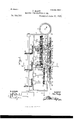
- Figure 1 is a plan View of myimproved machine
- Fig. 2, a front elevation
- Fig. 3 a section on the line m m of Fig. 1
- Fig. 4 a section on the line y y of Fig. 1.
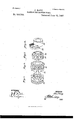
- Figs. 5, 6, 7, and S are detail perspective views of the parts carried by one of the counter-shafts from which motion is imparted to the wire-drawing drums;
- Fig. 10 a plan View of such modified construction, and
- Fig. 11 a front elevation of another modification of my invention.
- 5 is a counter-shaft journaled in the frame at right angles to the power-shaft 3
- 6 is a bevel-gear rigidon said coun tor-shaft, which meshes with a bevel-gear 7, rigid on the powershaft, whereby motion is imparted to the counter-shaft 5 from said power-shaft.
- a pinion tight on the counter-shaft 5 which meshes with a large gear 11 on the shaft 8, whereby motion is transmitted from the counter-shaft 5 to the shaft 8 and the drum 9 carried thereon.
- Extending from the frame is a bracket 12, to which is secured an ordinary die-block 13, through which the wire is drawn when it undergoes the first reducing operation.
- the die-block 13 is placed in proper relative position with respect to the periphery of the dru1n9, so that the wire will travel in a direct line from said die-block to the periphery of said drum, so that the wear on the die will be evenly distributed, as will be understood by reference to Figs. 1 and 2.
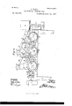
- 17 is a shaft journaled in the frame and parallel with the counter-shaft 14.
- the 21 22 are two large gears rigid on the shaft 17, the gear 21 being somewhat smaller in diameter than the gear 23.
- the pinion 19 meshes with the gear 21, while the pinion 2O meshes with the gear 22.
- 23 is a clutch-hub formed on one side of the pinion 19, and 24 is a clutch splined 011 the counter-shaft 14 in such manner as to be capable of a free sliding movement thereon, and said clutch is adapted to engage the h ub 23 of the pinion 19, so as to cause said pinion and clutch to revolve together.
- ratchet 25 is a ratchet formed on the pinion 20, and 26 is a spring-actuated pawl carried bya collar 27, rigid on the counter-shaft 14.
- the pawl 26 is adapted to engage the teeth of the ratchet 25 on the pinion 20, so as to cause the collar 27, on which said pawl is carried, and the pinion to revolve together.
- the object in equipping the shafts 14 17 with the different-sized pinions and gears, together with the clutch mechanism above described, is to cause the shaft 17, on which the reel or drum 18 is mounted, to be driven at two different speeds, the reason for which will be presently explained.
- 28 is a lever pivoted at 29 to a bracket or upright 30, extending from the frame, and 31 is a grooved pulley mounted on the upper extremity of said lever.
- the lower end of the lever 28 is provided with an overpoise 32.
- the wire 40 is first forced through the die 13 and then wound several times around the drum 9. From the drum 9 the wire is passed up and over the pulley 31, and thence under the pulley 38 to the die-block 36, through which it is drawn by the drum 18, around which said wire is wound several times before it is passed on to the next drawing mechanism.
- the overpoise 32 on the lower end of the lever 28 is of sufficient weight to counterbalance the weight of the parts on said lever and in addition thereto exert a slight but constant pull on the wire.
- the proportions of the pinion 19 and gear21 with respect to each other are calculated to be such as will cause the drum 18 to draw the wire through the die 36 a trifle faster than said wire is reeled off of the drum 9 when the shaft 17 is being driven by said pinion 20 and gear 22 with respect to each other are such as will cause the drum 18 to draw the wire through the die 36 a trifle slower than said wire is reeled off of said drum 9 when the shaft 17 is being driven by said pinion 20.
- variable speed of the drawing-drum 18 is made necessary owing to the fact that the metal of which the wire is composed is not of a uniform density, and will consequently vary in spots in degree of hardness and ductility, and therefore if two pieces of wire of a given length and thickness be drawn down to a size-smaller it will be found that the said two pieces of wire will not measure the same in length after being drawn down to such smaller size, and therefore, owing to the Variable quality of the wire, if the drawing-drum 18 were run at one certain speed either a quantity of wire would accumulate between the first drawing-drum and the die 36 or said wire would be drawn through said die faster than it would be reeled from said drum 9, and in a short while the strain thus created would cause the wire to break.
- the operation of the automatic clutchshifting mechanism is as follows: Suppose the clutch 24 to be in engagement with the pinion 19, as shown in Figs. 1 and 4. The drum 18 will then be rotated at its greatest speed, which will cause the length of wire which is passed around the pulleys 31 38 between the drums 9 18 to be gradually shortened, thus causing the lever 28 to be depressed, which through its connection with the clutch-lever will cause the clutch 24 to be thrown out of engagement with the pinion 19.
- the reel 41 is a reel upon which the wire is wound as it comes from the machine.
- the reel 41 is secured upon a shaft 42, which is journaled and supported in bearings 43, rigid with the frame.
- 44 is a belt-pulley 011 the end of the shaft 42, to which a belt (not shown) may be applied from any convenient nearby shaftin g to rotate the reel 41 to effect the winding of the finished wire thereon.
- Figs. 9and 10 I have shown a modified form of the clutch mechanism, and in this construction but one set of gears are used for driving the shaft 17.
- 45 is a pinion tight on the counter-shaft 14
- 46 is a large gear tight on the shaft 17 with which said pinion meshes.
- the bevel-gear 15 is tight on the counter-shaft 14, as described in my preferred construction, but the bevel-gear 1 6, with which said bevelgear 15 meshes, is in this instance loose on the power-shaft and has a hub 47, with which an ordinary friction-clutch 48 engages.
- the friction-clutch is of course splined on the power-shaft and is capable of a sliding movement toward and away from the hub of the bevel-gear 16.
- 49 is a collar tight on the power-shaft, which serves to keep the bevelgear 16 in proper position.
- the lever 28 in this construction is secured to a rock-shaft 50, journaled in bearings 51, rigid with the frame, and 52 is an overpoise secured to said rock-shaft, the function of this overpoise of course being the same as that ascribed to the overpoise 32.
- To the opposite end of the rock-shaft is secured a crank-arm 53.
- the clutch-lever 33 is pivoted at 54 to the frame, and 55 is a link, one end of which is pivotally connected to the upper end of the clutch-lever, while the other end is likewise connected to the end of the crank-arm 53.
- the proportions of the pinion 45 and gear 46 are such that the drum 18 will draw the wire through the die 36 a trifle faster than it is reeled from the drum 9, and therefore the tension on the wire will cause the lever 28 to be gradually depressed, and when this occurs the frictionclutch 48 will be withdrawn from engagement with the bevel-gear 16, which will cause said gear and parts operated thereby to slow up until the tension of the wire will permit the lever 28 to resume its elevated position, when the friction-clutch will be again brought in contact with the bevel-gearltl.
- Fig. 11 I have shown another modification of my invention wherein the variablespeed gears are dispensed with and the various wire-drawing drums are rotated at uniform speeds.
- the grooved pulley 31, mounted on the end of the lever 28, is in this instance merely a tension device for the wire.
- the lever 28 in this construction has no connection with any clutch-shifting mechanism and acts only as a take-up to compensate for the variable ductility of the wire being drawn.
- a wire-drawingmachine In a wire-drawingmachine, the die-block and winding-reel, a plurality of driving-gears of differing size, one or the other of which may be thrown into operative relation with the reel, a shifter over which the wire passes, said shifter controlling the engagement of said gears with the reel, and a tension device against the pressure of which the shifter operates, all combined substantially as described.
- the die-block, the winding-reel, and a driving-shaft provided with a plurality of sets of drivinggears, one set driving the reel at a minimum speed and having a member free to yield and permit the driving of the reel by the other set at maximum speed, and means controlled by the wire for engaging one or the other sets of driving-gears with the winding-reel, all combined substantially as described.
- a wire-drawingmachine the die-block, a winding-reel by which the wire is drawn positively from said die-block, a plurality of positively acting driving gears either of which may be thrown into operation to propel the winding-gear, and an automatic shifter by which the wire operates to shift one or another of the .lriving-gears into operation, all combined substantially as described.
Landscapes
- Engineering & Computer Science (AREA)
- Mechanical Engineering (AREA)
- Metal Extraction Processes (AREA)
Description
(No Model.) 8 Sheets -Sl1eet M.
J. RADY. MACHINE FOR DRAWING WIRE.
No. 584,792. Patented June 22,1897
WlTN ESSESI INVENTDH bk y.
a ATTY ncnms PETERS co, FHOTO-LITHQ. wxsumu'rou. n. c.
8 Shets-Sheet 2.
(No Model.-)
J. RADY. MACHINE FOR DRAWING WIRE.
* INVENTUR Jamwtuf'y Patented June 22, 1897.
TTY
T: ucnms PETERS co, wuru-umoswnsnmmou, n. c.
(No Model.) a Sheets-Sheet 3.
r J. RADY.
MACHINE FOR DRAWING WIRE.
Patented June 22, 189 7.
m: uonms versus ca, Pun-mums" WASnYNGTDN. b. c
8 Sheets-Sheet 5.
(No Model.)
J BABY I MACHINE FOR DRAWING WIRE.
Patented June 22, 18-97;
INVENTUH Jahnwaz y WITNESSES:
' ATTI'Y NOTO-L mo" WASNINGYW. n. c.
8 Sheets-Sheet 6.
ATTY
Patented June 22,1897.
J. RADY. MACHINE FOR DRAWING WIRE.
(No Model.)
wlTNEsSEsi (No Model.) '8 Sheets-Sheet; 8.
J. RADY. MACHINE FOR DRAWING WIRE.
No. 584,792. Patented June 22, 1897.
WITNESS ES:
INVENTOR John 1w: moms PETERS cu. wgmaumo wsmuqrcm. ac
NrrEn STATES ATENT FFICE.
JOHN RADY, OF GEORGETOWN, CONNECTICUT.
MACHINE FOR DRAWING- WIRE.
SPECIFICATION forming part of Letters Patent No. 584,792, dated June 22, 1897.. Application filed November 1, 1895. Serial No. 567,610. (No model.)
To all whom it may concern:
Be it known that I, JOHN RADY, a citizen of the United States, residing at Georgetown, in the county of Fairfield and State of Connecticut, have invented certain new and usef Lil Improvements in Machines for Drawing lVire; and I do hereby declare the following to be a full, clear, and exact description of the invention, such as will enable others skilled in the art to which it appertains to make and use the same.
My invention relates to certain new and useful improvements in machines for drawing wire, and has for its object to provide a machine of this description which will draw wire down to a required small size without breaking said wire, thus greatly increasing the output of the machine and also rendering the product of much finer quality.
Referring to the accompanying drawings, which form a part of this specification, Figure 1 is a plan View of myimproved machine; Fig. 2, a front elevation; Fig. 3, a section on the line m m of Fig. 1; Fig. 4, a section on the line y y of Fig. 1. Figs. 5, 6, 7, and S are detail perspective views of the parts carried by one of the counter-shafts from which motion is imparted to the wire-drawing drums; Fig. 9, a rear View of a modified form of my machine; Fig. 10, a plan View of such modified construction, and Fig. 11 a front elevation of another modification of my invention.
Similar numbers of reference denote like parts in the several figures of the drawings.
1 is the frame, supported by the usual legs 2.
3 is the power-shaft, journaled within the frame at the rear of the machine, and dis a power-pulley mounted on the end of said shaft.
5 is a counter-shaft journaled in the frame at right angles to the power- shaft 3, and 6 is a bevel-gear rigidon said coun tor-shaft, which meshes with a bevel-gear 7, rigid on the powershaft, whereby motion is imparted to the counter-shaft 5 from said power-shaft.
8 is a shaft journaled in the frame parallel with the counter-shaft 5, and rigidly mounted on the forward end of said shaft 8 is a reel or drum 9.
10 is a pinion tight on the counter-shaft 5, which meshes with a large gear 11 on the shaft 8, whereby motion is transmitted from the counter-shaft 5 to the shaft 8 and the drum 9 carried thereon. Extending from the frame is a bracket 12, to which is secured an ordinary die-block 13, through which the wire is drawn when it undergoes the first reducing operation. Of course the die-block 13 is placed in proper relative position with respect to the periphery of the dru1n9, so that the wire will travel in a direct line from said die-block to the periphery of said drum, so that the wear on the die will be evenly distributed, as will be understood by reference to Figs. 1 and 2.
Thus far I have described only the instrumentalities which effect the first drawing operation, and said instrumentalities are of ordinary construction, for the difficulty in reducing a thick wire rod down to a very thin strand of wire is not in the first drawing operation, but in the succeeding ones.
As the several sets of mechanisms for further reducing the wire after the first drawing operation has been performed are precisely alike,with the exception of the size of the gears employed therein, I shall describe but one of such mechanisms, the description of one set being deemed sufficient for them all.
In the drawings I have illustrated but two of such sets of mechanisms for reducing the wire after the first drawing operation has been performed; but it will be understood that a greater number may beem ployed when it is desired to reduce the wire to a much finer gage.
It must also be understood that the multiplication of parts,so that a plurality of Wires may be drawn simultaneously, may be made Without departing from the spirit of this invention.
14 is a counter-shaft similar to the countershaft 5 and likewise journaled in the frame.
15 is a bevel-gear tight 011 the counter-shaft 14, which meshes with a bevel-gear 16, tight on the power-shaft 3, whereby motion is imparted to said counter-shaft from the powershaft.
17 is a shaft journaled in the frame and parallel with the counter-shaft 14.
18 is a reel or drum similar to the drum 9, rigidly mounted on the forward end of the shaft 17.
19 20 are two pinions loose on the countershaft 14, the pinion 19 being somewhat larger than the pinion 20, and either one of these pinions is capable of turning independent of the other.
21 22 are two large gears rigid on the shaft 17, the gear 21 being somewhat smaller in diameter than the gear 23. The pinion 19 meshes with the gear 21, while the pinion 2O meshes with the gear 22.
23 is a clutch-hub formed on one side of the pinion 19, and 24 is a clutch splined 011 the counter-shaft 14 in such manner as to be capable of a free sliding movement thereon, and said clutch is adapted to engage the h ub 23 of the pinion 19, so as to cause said pinion and clutch to revolve together.
25 is a ratchet formed on the pinion 20, and 26 is a spring-actuated pawl carried bya collar 27, rigid on the counter-shaft 14. The pawl 26 is adapted to engage the teeth of the ratchet 25 on the pinion 20, so as to cause the collar 27, on which said pawl is carried, and the pinion to revolve together.
When the clutch 24 is in engagement with the pinion 19, the gear 21 (with which said pinion 19 meshes) and gear 22, rigid on the shaft 17,will cause the motion of said pinion 19 tobe transmitted to the pinion 20, and said pinion 20 will be caused to revolve faster than said pinion 19, because the motion of said pinion 19 will have been slightly multiplied by the gears 21 22 by reason of their difference in diameters. The pinion 20 will now be revolved faster than the shaft on which it is carried, and the pawl 26 will slip idly over the teeth of the ratchet 25, all of which will be readily understood by reference to Figs. 1, 3, and 4.
When the clutch 24 is disengaged from the pinion 19, the pawl 26 will engage the teeth of the ratchet and cause the pinion 20 to be revolved with the shaft on which it is carried in such manner as if said pinion were rigidly mounted thereon. This will cause the shaft 17 to be revolved at a slower speed than when the clutch 24 is in engagement with the pinion 19, and said pinion will of course be loose and free to turn idly around the shaft on which it is carried.
The object in equipping the shafts 14 17 with the different-sized pinions and gears, together with the clutch mechanism above described, is to cause the shaft 17, on which the reel or drum 18 is mounted, to be driven at two different speeds, the reason for which will be presently explained.
Referring particularly to Figs. 1, 2, and 4, 28 is a lever pivoted at 29 to a bracket or upright 30, extending from the frame, and 31 is a grooved pulley mounted on the upper extremity of said lever. The lower end of the lever 28 is provided with an overpoise 32.
33 is a clutch-lever pivoted between cars 34, rigid with the frame, and 35 is a link the upper end of which is pivotally connected to the lever 28, while the lower end of said link is pivotall y connected to the end of said clutchlever 33, as clearly shown in Fig. 4.
36 is an ordinary die-block, similar to the die 13, but of a smaller size, and secured in proper relative position on a bracket 37, eX- tending from the frame.
38 is a grooved pulley mounted on an upright 39, rigid with the frame, the function of said pulley being to properly guide the wire to the die-block 36.
The wire 40 is first forced through the die 13 and then wound several times around the drum 9. From the drum 9 the wire is passed up and over the pulley 31, and thence under the pulley 38 to the die-block 36, through which it is drawn by the drum 18, around which said wire is wound several times before it is passed on to the next drawing mechanism. The overpoise 32 on the lower end of the lever 28 is of sufficient weight to counterbalance the weight of the parts on said lever and in addition thereto exert a slight but constant pull on the wire. The proportions of the pinion 19 and gear21 with respect to each other are calculated to be such as will cause the drum 18 to draw the wire through the die 36 a trifle faster than said wire is reeled off of the drum 9 when the shaft 17 is being driven by said pinion 20 and gear 22 with respect to each other are such as will cause the drum 18 to draw the wire through the die 36 a trifle slower than said wire is reeled off of said drum 9 when the shaft 17 is being driven by said pinion 20. The variable speed of the drawing-drum 18 is made necessary owing to the fact that the metal of which the wire is composed is not of a uniform density, and will consequently vary in spots in degree of hardness and ductility, and therefore if two pieces of wire of a given length and thickness be drawn down to a size-smaller it will be found that the said two pieces of wire will not measure the same in length after being drawn down to such smaller size, and therefore, owing to the Variable quality of the wire, if the drawing-drum 18 were run at one certain speed either a quantity of wire would accumulate between the first drawing-drum and the die 36 or said wire would be drawn through said die faster than it would be reeled from said drum 9, and in a short while the strain thus created would cause the wire to break.
The operation of the automatic clutchshifting mechanism is as follows: Suppose the clutch 24 to be in engagement with the pinion 19, as shown in Figs. 1 and 4. The drum 18 will then be rotated at its greatest speed, which will cause the length of wire which is passed around the pulleys 31 38 between the drums 9 18 to be gradually shortened, thus causing the lever 28 to be depressed, which through its connection with the clutch-lever will cause the clutch 24 to be thrown out of engagement with the pinion 19. As soon as the clutch 24 is disengaged from the pinion 19 the pawl 26 will be permitted to engage the ratchet 25, which will cause the shaft 17 and drum 18 carried thereon to be driven by the pinion 20, which, as previously eX- plained, causes said drum to draw the wire through the die 36 slower than it is reeled from the drum 9. The lever 28 will now be permitted to gradually assume its former elevated position, which of course will effect the engagement of the clutch 24 with the pinion 19 and restore the faster speed to said drum 18. This changing from one speed to another is continued throughout the time the machine is drawing wire with more or less regularity, and owing to this fact no great quantity of wire can accumulate between any two of the drums, and also the breaking of the wire between any two of said drums is effectually prevented.
41 is a reel upon which the wire is wound as it comes from the machine. The reel 41 is secured upon a shaft 42, which is journaled and supported in bearings 43, rigid with the frame. 44 is a belt-pulley 011 the end of the shaft 42, to which a belt (not shown) may be applied from any convenient nearby shaftin g to rotate the reel 41 to effect the winding of the finished wire thereon.
. In Figs. 9and 10 I have shown a modified form of the clutch mechanism, and in this construction but one set of gears are used for driving the shaft 17. Referring to these figures, 45 is a pinion tight on the counter-shaft 14, and 46 is a large gear tight on the shaft 17 with which said pinion meshes. The bevel-gear 15 is tight on the counter-shaft 14, as described in my preferred construction, but the bevel-gear 1 6, with which said bevelgear 15 meshes, is in this instance loose on the power-shaft and has a hub 47, with which an ordinary friction-clutch 48 engages. The friction-clutch is of course splined on the power-shaft and is capable of a sliding movement toward and away from the hub of the bevel-gear 16. 49 is a collar tight on the power-shaft, which serves to keep the bevelgear 16 in proper position. The lever 28 in this construction is secured to a rock-shaft 50, journaled in bearings 51, rigid with the frame, and 52 is an overpoise secured to said rock-shaft, the function of this overpoise of course being the same as that ascribed to the overpoise 32. To the opposite end of the rock-shaft is secured a crank-arm 53. The clutch-lever 33 is pivoted at 54 to the frame, and 55 is a link, one end of which is pivotally connected to the upper end of the clutch-lever, while the other end is likewise connected to the end of the crank-arm 53. The proportions of the pinion 45 and gear 46 are such that the drum 18 will draw the wire through the die 36 a trifle faster than it is reeled from the drum 9, and therefore the tension on the wire will cause the lever 28 to be gradually depressed, and when this occurs the frictionclutch 48 will be withdrawn from engagement with the bevel-gear 16, which will cause said gear and parts operated thereby to slow up until the tension of the wire will permit the lever 28 to resume its elevated position, when the friction-clutch will be again brought in contact with the bevel-gearltl.
In Fig. 11 I have shown another modification of my invention wherein the variablespeed gears are dispensed with and the various wire-drawing drums are rotated at uniform speeds. The grooved pulley 31, mounted on the end of the lever 28, is in this instance merely a tension device for the wire. The lever 28 in this construction has no connection with any clutch-shifting mechanism and acts only as a take-up to compensate for the variable ductility of the wire being drawn.
I have found by experience that this construc tion is admirably adapted for use in drawing wire of the finer gages, and for this class of work variable speeds for the wire drawing drums is not absolutely necessary.
1 do not wish to be limited to the exact construction shown and described, since the various salient features may be altered or modified without departing from the spirit of my invention.
Having thus described my invention, what I claim as new, and desire to secure by Letters Patent, is-
1. The combination of the frame, the powershaft journaled therein, the die-block through which the wire passes during the first drawing operation, a drum mounted on a shaft journaled in the frame, suitable gearing be tween said drum shaft and power shaft whereby said drum-shaft is driven at a uniform speed, the shaft 17 journaled in the frame and carrying a drawing-drum, the gears 21, 22, tight on the shaft 17, the pinions 19, 20, loose on a counter-shaft driven from the power-shaft by suitable gearing, the die-block 36 through which the wire passes during the second drawing operation, and instrumentalities automatically controlled by the wire for causing the shaft 17 to be first driven by one of the pinions 19, 20, and then by the other, whereby two different speeds are imparted to the drawing-drum, substantially as set forth.
2. The combination of the frame, the dieblock 36 secured in proper relative position thereon, the shaft 17 journaled in. said frame and carrying a drawing-drum, the gears 21, 22, tight on said shaft 17 and meshing with pinions 19, 20, loose on the counter-shaft 14, the pawl 26 carried on the shaft 14 and adapted to engage the ratchet 25 formed with the pinion 20, whereby said pinion is rendered in effect tight on said shaft 14, a clutch adapted to engage the pinion 19, whereby said pinion is caused to revolve with said shaft 14, and means automatically controlled by the wire for causing the engagement and disengageternatively connected to said winding-reel, and a shifting piece over which the wire passes from the die-block and connected to said gears, to shift the one or the other into driving connection with the reel, all combined substantially as described.
4. In a wire-drawin g machine, a die-block, a winding-reel and a plurality of drivinggears by either one of which said reel is propelled, and means operated on by the Wire after passing the die-block, by which the engagement of one or the other drivinggear with the reel is determined, all combined substantially as described.
5. In a wire-drawing machine, a series of die-blocks through which the wire passes successively, a series of drawing-reels, one succeeding each die-block, a shifting piece over which the wire passes between the die and reel, and alternative trains of positively-actuated driving-gears controlled by said shifting piece to automatically and positively speed the winding-reels, all combined substantially as described.
6. In a wire-drawing machine, a die-block and a winding-reel, and a power-dri\-'en counter-shaft bearing a plurality of driving-gears alternatively in driving relation with the winding-reel, a clutch in position to opera-- tively engage one or the other of these gears, and a shifter, over which the wire passes, and by which the clutch may be automatically engaged with one or the other driving-gear, all combined substantially as described.
'7. In a wire-drawingmachine, the die-block and winding-reel, a plurality of driving-gears of differing size, one or the other of which may be thrown into operative relation with the reel, a shifter over which the wire passes, said shifter controlling the engagement of said gears with the reel, and a tension device against the pressure of which the shifter operates, all combined substantially as described.
8. In a wire-drawin g machine,the die-block, the winding-reel, and a driving-shaft provided with a plurality of sets of drivinggears, one set driving the reel at a minimum speed and having a member free to yield and permit the driving of the reel by the other set at maximum speed, and means controlled by the wire for engaging one or the other sets of driving-gears with the winding-reel, all combined substantially as described.
9. In a wire-drawingmachine,the die-block, a winding-reel by which the wire is drawn positively from said die-block, a plurality of positively acting driving gears either of which may be thrown into operation to propel the winding-gear, and an automatic shifter by which the wire operates to shift one or another of the .lriving-gears into operation, all combined substantially as described.
In testimony whereof I affiX my signature in presence of two witnesses.
JOHN RADY.
Vitnesses:
J. S. FINcrI, T. E. FLoon.
Publications (1)
| Publication Number | Publication Date |
|---|---|
| US584792A true US584792A (en) | 1897-06-22 |
Family
ID=2653462
Family Applications (1)
| Application Number | Title | Priority Date | Filing Date |
|---|---|---|---|
| US584792D Expired - Lifetime US584792A (en) | Machine foe deawing wiee |
Country Status (1)
| Country | Link |
|---|---|
| US (1) | US584792A (en) |
-
0
- US US584792D patent/US584792A/en not_active Expired - Lifetime
Similar Documents
| Publication | Publication Date | Title |
|---|---|---|
| US584792A (en) | Machine foe deawing wiee | |
| US805265A (en) | Spooling-machine. | |
| US1039876A (en) | Twisting-machine. | |
| US796261A (en) | Wire-drawing machine. | |
| US1036981A (en) | Transmission-gearing. | |
| US427572A (en) | Machine for cutting collar or cuff blanks | |
| US927037A (en) | Machine for coiling metal. | |
| US586084A (en) | duryea | |
| US684946A (en) | Wire drawing and spooling machine. | |
| US622329A (en) | Francis h | |
| US241271A (en) | allis | |
| US1316935A (en) | Continuous-wire-drawing machine. | |
| US975641A (en) | Continuous-wire-drawing machine. | |
| US795279A (en) | Winding-machine. | |
| US1219594A (en) | Tension mechanism for testing-machines. | |
| US1277029A (en) | Blocking attachment for strip-mills. | |
| US1344568A (en) | Wire-drawing machine | |
| US158331A (en) | Improvement in machines for balling twine | |
| US1980610A (en) | Rayon spinning machine | |
| US1550292A (en) | Antispeeding device for wire-drawing drums | |
| US993488A (en) | Fence-machine. | |
| US581274A (en) | Balling-machine | |
| US772449A (en) | Fence-loom. | |
| US244618A (en) | Wire testing machine | |
| US458224A (en) | Apparatus for treating cloth |