US5836047A - Vacuum cleaner for both upright and canister modes - Google Patents
Vacuum cleaner for both upright and canister modes Download PDFInfo
- Publication number
- US5836047A US5836047A US08/795,186 US79518697A US5836047A US 5836047 A US5836047 A US 5836047A US 79518697 A US79518697 A US 79518697A US 5836047 A US5836047 A US 5836047A
- Authority
- US
- United States
- Prior art keywords
- section
- air
- connector section
- vacuum cleaner
- upright
- Prior art date
- Legal status (The legal status is an assumption and is not a legal conclusion. Google has not performed a legal analysis and makes no representation as to the accuracy of the status listed.)
- Expired - Fee Related
Links
Images


Classifications
-
- A—HUMAN NECESSITIES
- A47—FURNITURE; DOMESTIC ARTICLES OR APPLIANCES; COFFEE MILLS; SPICE MILLS; SUCTION CLEANERS IN GENERAL
- A47L—DOMESTIC WASHING OR CLEANING; SUCTION CLEANERS IN GENERAL
- A47L5/00—Structural features of suction cleaners
- A47L5/12—Structural features of suction cleaners with power-driven air-pumps or air-compressors, e.g. driven by motor vehicle engine vacuum
- A47L5/22—Structural features of suction cleaners with power-driven air-pumps or air-compressors, e.g. driven by motor vehicle engine vacuum with rotary fans
- A47L5/225—Convertible suction cleaners, i.e. convertible between different types thereof, e.g. from upright suction cleaners to sledge-type suction cleaners
-
- A—HUMAN NECESSITIES
- A47—FURNITURE; DOMESTIC ARTICLES OR APPLIANCES; COFFEE MILLS; SPICE MILLS; SUCTION CLEANERS IN GENERAL
- A47L—DOMESTIC WASHING OR CLEANING; SUCTION CLEANERS IN GENERAL
- A47L5/00—Structural features of suction cleaners
- A47L5/12—Structural features of suction cleaners with power-driven air-pumps or air-compressors, e.g. driven by motor vehicle engine vacuum
- A47L5/22—Structural features of suction cleaners with power-driven air-pumps or air-compressors, e.g. driven by motor vehicle engine vacuum with rotary fans
- A47L5/28—Suction cleaners with handles and nozzles fixed on the casings, e.g. wheeled suction cleaners with steering handle
- A47L5/32—Suction cleaners with handles and nozzles fixed on the casings, e.g. wheeled suction cleaners with steering handle with means for connecting a hose
-
- A—HUMAN NECESSITIES
- A47—FURNITURE; DOMESTIC ARTICLES OR APPLIANCES; COFFEE MILLS; SPICE MILLS; SUCTION CLEANERS IN GENERAL
- A47L—DOMESTIC WASHING OR CLEANING; SUCTION CLEANERS IN GENERAL
- A47L5/00—Structural features of suction cleaners
- A47L5/12—Structural features of suction cleaners with power-driven air-pumps or air-compressors, e.g. driven by motor vehicle engine vacuum
- A47L5/22—Structural features of suction cleaners with power-driven air-pumps or air-compressors, e.g. driven by motor vehicle engine vacuum with rotary fans
- A47L5/36—Suction cleaners with hose between nozzle and casing; Suction cleaners for fixing on staircases; Suction cleaners for carrying on the back
- A47L5/362—Suction cleaners with hose between nozzle and casing; Suction cleaners for fixing on staircases; Suction cleaners for carrying on the back of the horizontal type, e.g. canister or sledge type
Definitions
- the present invention relates to a vacuum cleaner, and more particularly to a vacuum cleaner for both upright and canister modes.
- a vacuum cleaner may be classified into a canister mode vacuum cleaner and an upright mode vacuum cleaner.
- a cleaner body has a dirt collecting chamber and an air suction chamber.
- the cleaner body and a brush section are separated from each other, and they are connected with each other through suction pipes and a flexible hose. Further, a grip is formed on one of the suction pipes connected to the brush section, and thereby the cleaner body and the brush section are moved together when the cleaner is used.
- the cleaner body is provided with wheels so that it can be moved easily.
- the canister mode vacuum cleaner has advantages in that handling of the cleaner during a cleaning operation is easy, and every nook and corner can be cleaned.
- the cleaner occupies large space when stored because its entire volume is large. Moreover, maintenance of airtightness, and assembling for storage use or disassembling for cleaning use are difficult because the cleaner has many members to be connected with each other such as suction pipes, a flexible hose, etc., and because a suction air pipe is long. Furthermore, the handling of the cleaner during a cleaning operation may cause annoyance to a user because the cleaner body and the brush section are moved independently from each other.
- the upright mode vacuum cleaner when using the upright mode vacuum cleaner, a brush section is connected directly to a lower part of the cleaner body without using suction pipes and a flexible hose, etc., and a grip is disposed directly at an upper part of the cleaner body. Therefore, the upright mode vacuum cleaner has advantages in that the handling of the cleaner during a cleaning operation is simple, the volume thereof is small, and the storage thereof is convenient. However, since the cleaner body and the brush section are moved altogether, the weight of handling by a user during a cleaning operation is too heavy, and it is also difficult to clean every nook and corner.
- FIG. 1 is a schematic constructional view of the conventional dual mode vacuum cleaner.
- a canister 20 is attached to one of a plurality of suction pipes 30 which is connected through attachment members 21 such as clamps disposed at even spaces along the suction pipe 30. Air suctioned through a brush section 40 is exhausted through the brush section 40 after having been filtered through the canister 20.
- the conventional dual mode vacuum cleaner aims to provide a dual mode vacuum cleaner wherein suction efficiency increases without increasing the driving force of the motor.
- the conventional dual mode vacuum cleaner does not disclose both the construction and shape of the attachment members 21 for assembling the canister 20 with the suction pipes 30, and because the filtered air is exhausted through the brush section 40, the dirty matter near an area to be cleaned is scattered by the exhausted air, thereby reducing cleaning efficiency.
- the present invention comprises a cleaner body section having a first recess in which a first connector section is placed, which is formed at a first or bottom side of the cleaner body section, and a second recess in which a second connector section is placed, which is formed at second or rear side of the cleaner body section, wherein the first and second sides form a right angle, and a couple of fitting portions are provided at the first side adjacent to the second side, the first and second fitting portions are spaced at a predetermined distance from each other and each has first and second slots shaped like an arc, respectively.
- the vacuum cleaner for both upright and canister modes further comprises a brush section being in contact with a place to be cleaned and providing an air passageway therein for the dirt-bearing air and the first connector section having first and second protrusions which protrude in the opposite directions to insert into the first and second slots, respectively, and the first connector section detachably connected to the brush section, and for providing an air passageway for the dirt-bearing air to enter from the brush section, wherein the first and second protrusions are slidably connected in the first and second slots, respectively, while the first recess receives the first connector section to be slid along the first and second protrusions.
- the vacuum cleaner for both upright and canister modes comprises the second connector section fixedly inserted in the second recess and connected to the first connector section, and for providing an air passageway for the dirt-bearing air, and a suction pipe section detachably connecting the second connector section with the cleaner body section and for providing an air passageway for the dirt-bearing air to enter from the second connector section to the cleaner body section when in upright mode, whereas the suction pipe section detached from the second connector section is detachably connected to the brush section without the first connector section to provide an air passageway for the dirt-bearing air to enter directly from the brush section to the suction pipe section when in canister mode.
- the vacuum cleaner of the present invention can be used in both a canister mode and an upright mode without reduction in cleaning performance and easily converted from the canister mode to the upright mode and vice versa.
- FIG. 1 is a schematic constructional view of a conventional dual mode vacuum cleaner
- FIG. 2 is an exploded perspective view of a vacuum cleaner for both upright and canister modes according to an embodiment of the present invention
- FIG. 2A is a first or bottom side view in connection with a first connector section when viewed in the direction of arrow A of FIG. 2;
- FIG. 2B is an exploded perspective view of the first connector section of FIG. 2;
- FIG. 2C is an exploded perspective view of a second connector section of FIG. 2;
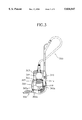
- FIG. 3 is a partially cut-away schematic side elevation of the cleaner shown in FIG. 2 in an upright mode in which the cleaner body and the ground make a right angle;
- FIG. 4 is a perspective view of the vacuum cleaner of FIG. 2 for use in an upright mode in which the cleaner body and the ground form a right angle;
- FIG. 5 is a perspective view of the vacuum cleaner of FIG. 2 for use in an upright mode in which the cleaner body and the ground make an angle of 60°;
- FIG. 6 is a perspective view of the vacuum cleaner of FIG. 2 in use as an upright mode in which the cleaner body and the ground form an angle of 45°;
- FIG. 7 is a perspective view of the vacuum cleaner of FIG. 2 for use in a canister mode in which the suction pipe section is directly connected to the brush section.
- FIG. 2 is an exploded perspective view of a vacuum cleaner for both upright and canister modes according to the embodiment of the present invention
- FIG. 2A is a view of a first side of a cleaner body section in connection with a first connector section when viewed in the direction of arrow A of FIG. 2
- FIG. 3 is a partially cut-away schematic side elevation view of the cleaner shown in FIG. 2 in an upright mode in which the cleaner body and the ground form a right angle.
- the vacuum cleaner according to an embodiment of the present invention comprises a cleaner body section 300, a suction pipe section 350, a first connector section 360a, a second connector section 360b, and a brush section 306.
- the cleaner body section 300 has a first recess 312a in which the first connector section 360a is placed, which is formed at a first or bottom side 312c, and a second recess 312b for housing the second connector section 360b, which is formed at a second or rear side 312d.
- the first or bottom side 312c and the second or rear side 312d form a right angle.
- a couple of fitting portions 340a, 340b are provided at the first side 312c adjacent to the second side 312d.
- the first and second fitting portions 340a and 340b are spaced at a predetermined distance from each other, and each has first and second slots 341a and 341b shaped like an arc, respectively.
- the cleaner body section 300 intakes dirt-bearing air, filters the intaken air to eliminate the dirt from the dirt-bearing air, and exhausts the dirt-eliminated or clean air.
- the brush section 306 is in contact with a place to be cleaned and provides an air passageway therein for the dirt-bearing air to flow from the place to the first connector section 360a.
- the first connector section 360a has first and second protrusions 330a and 330b which protrude in the opposite directions to insert into the first and second slots 341a and 341b, respectively.
- the first and second protrusions 330a and 330b are slidably connected in the first and second slots 341a and 341b, respectively, while the first recess 312a is placed on the first connector section 360a to be slid along the first and second protrusions 330a and 330b.
- the brush section 306 is detachably connected to the first connector section 360a to provide the air passageway for the dirt-bearing air to enter from the brush section 306.
- the second connector section 360b is fixedly inserted in the second or rear recess 312b and connected to the first connector section 360a to provide an air passageway for the dirt-bearing air.
- the suction pipe section 350 connects the second connector section 360b with the cleaner body section 300 to provide an air passageway for the dirt-bearing air to flow from the second connector section 360b to the cleaner body section 300.
- the suction pipe section 350 is detachably connected to the second connector section 360b.
- the suction pipe section 350 detached from the second connector section 360b can be detachably connected to the brush section 306 without both the first connector section 360a and the second connector section 360b to provide an air passageway for the dirt-bearing air to pass directly from the brush section 306 to the suction pipe section 350.
- the cleaner body section 300 encloses a dirt collecting chamber 303 and a cleaner motor chamber 305, as can be seen in the conventional vacuum cleaner.
- Reference numerals 304 and 305a denote a dirt-collecting envelope filter and a cleaner motor, respectively. Both chambers 303 and 305 are divided by a partition 302 having a hole (not shown) which communicates both chambers 303 and 305.
- the second or rear side 312d of the body section 300 has two openings 318 (only one shown) each communicating with each air exhaust portion 311a, 311b (explained later) in order for the dirt-eliminated air to flow into the corresponding air exhaust portions 311a, 311b.
- the air intaken into the air exhaust portion 311a is exhausted through plural air exhaust ports 319.
- reference numerals 321, 321k, 320a and 320b denote a first main wheel, a second main wheel, a first auxiliary wheel and a second auxiliary wheel, respectively.
- the second or rear side 312d of the cleaner body section 300 has first and second air exhaust portions 311a and 311b which are separated oposite from each other.
- the second recess 312b is formed between the first and second air exhaust portions 311a and 311b.
- Each of the first and second air exhaust portions 311a and 311b has the plurality of air exhaust ports 319.
- Upper portions of the first and second air exhaust portions 311a and 311b have first and second grooves 321a and 321b, respectively.
- the first and second grooves 321a and 321b accommodate first and second auxiliary wheels 320a and 320b, respectively.
- the first and second grooves 321a and 321b are formed on each side of the first and second air exhaust portions 311a and 311b each of which is parallel with the second recess 312b.
- the cleaner body section 300 has a third or left side 301a and a fourth or right side 301b which are in parallel and opposite to each other and each of which forms a right angle with respect to both the first side 312c and the second side 312d.
- the third side 301a has a third recess 322a for accommodating the first main wheel 321.
- the third recess 322a is formed in a shape corresponding to the first main wheel 321.
- the third recess 322a has an opening 321i to receive a center shaft (not shown) of the first main wheel 321.
- the fourth side 301b has a fourth recess and an opening (both not shown) similar to a configuration of the third side 301a.
- FIG. 2B is an exploded perspective view of the first connector section of FIG. 2.
- the first connector section 360a connected with the first and second slots 341a and 341b through the first and second protrusions 330a and 330b is placed between the first and second main wheels 321a and 321b.
- the first connector section 360a has a first container 314 and a first air guider 316.
- the first container 314 is formed in a rectangular box shape.
- the rectangular box has an open side 330c and a front side 330d having a first center hole 330e.
- the front side 330d is opposite to the open side 330c.
- the first and second protrusions 330a and 330b extend in opposite directions from each other from the upper surface of the first connector section 360a, respectively.
- the first air guider 316 has a first lid 316a having a first lid hole 316b on the center portion thereof and a first hose 316f.
- the first hose 316f is slightly curved and fixedly inserted in the first lid hole 316b.
- one end portion of the first hose 316f is also inserted in the first center hole 330e.
- the first lid 316a covers the open side 330c and is fixed by a plurality of first engagement members 316m such as screws.
- the one end portion of the first hose 316f protrudes through the first center hole 330e to be detachably connected with a brush hose 306a to provide an air passageway from the brush section 306 to the first connector section 360a.
- FIG. 2C is an exploded perspective view of a second connector section of FIG. 2.
- the second connector section 360b is fixedly inserted in the second recess 312b.
- the second connector section 360b has a second container 313 and a second air guider 313f.
- the second container 313 is formed in a rectangular box shape.
- the rectangular box has an open side 313c and a bottom side 313d having a second center hole 313a.
- the bottom side 313d is opposite to the open side 313c.
- the second air guider 313f has a second lid 317a, and a second hose 317 having a flexible portion 329.
- the second hose 317 is slightly curved and is fixedly inserted in the second lid hole 317b.
- one end portion, including the flexible portion 329, of the second hose 317 is also inserted in the second center hole 313a.
- the second lid 317a covers the open side 313c and is fixed by a plurality of second engagement members 317m such as screws.
- the one end portion of the second hose 317 is extended through the second center hole 313a in order for a part of the flexible portion 329 to be connected in the other end portion of the first hose 316f, so that an air passageway is provided from the first connector section 360a to the second connector section 360b.
- the suction pipe section 350 may have a plurality of sectioned suction pipes 350a, 350b, a grip 308, and a flexible hose 309, to be easily operated by hand while moving the cleaner or the suction pipe section 350.
- one end of the sectioned suction pipe 350b is detachably connected to the other end portion of the second hose 317 (FIG. 2C).
- the one end of the sectioned suction pipe 350b is detachably connected to the brush hose 306a (FIG. 2B) to provide an air passageway directly from the brush section 306 to the cleaner body section 300.
- FIGS. 4, 5 and 6 are perspective views of the dual mode vacuum cleaner of FIG. 2 for use in an upright mode in which the cleaner body and the ground form a right angle, an angle of 60°, and an angle of 45°, respectively.
- the brush hose 306a of the brush section 306 is connected to the one end portion of the first hose 316 which is extended through the first center hole 330e of the first connector 314.
- the other end portion of the first hose 316 extended through the first hole of the first lid 316a is fixedly connected to one end portion of the flexible portion 329 of the second hose 317 (FIG.
- the first connector section 360a and the second connector section 360b may form various angles up to a right angle with respect to each other due to the flexible portion 329 of the second hose 317.
- the one end portion of the second hose 317 which is extended through the hole of the second lid 317a is detachably connected to one end of the second suction pipe 350b of the suction pipe section 350 (FIG. 2).
- the second connector section 360b is fixedly inserted into the second recess 312b, and the first or bottom side 312c of the cleaner body section 300 is placed on the first connector section 360a, and the first and second protrusions 330a and 330b of the first connector section 360a are slidably inserted in the first and second slots 341a and 341b (FIG. 2A).
- the cleaner body section 300 forms a right angle with respect to the ground when the vacuum cleaner 1 is used in the upright mode, and the first side 312c of the cleaner body section 300 is completely placed on the first connector section 360a, and the first protrusion 330a is at one end of the first slot 341a adjacent to the brush section 306.
- the first connector section 360a when force is applied to the grip 308 in the directions of arrows B and C, the first connector section 360a is still placed on the ground, but the first or bottom side 312c of the cleaner body section 300 is lifted from the upper surface of the first connector section 360a, in which the first protrusion 330a slides backwards along the first slot 341a. At an angle of 45°, the protrusion 330a is at another end of the first slot 341a adjacent to the second connector section 360b. In the upright mode, the first and second main wheels are used to move the vacuum cleaner.
- FIG. 7 is a perspective view of the vacuum cleaner of FIG. 2 for use in a canister mode, in which the suction pipe section 350 is directly connected to the brush section 306.
- the sectioned suction pipe 350b of the suction pipe section 350 is detached from the second connector section 360b, and the brush section 306 is detached from the first connector section 360a.
- the detached sectioned suction pipe 350b is connected to the brush hose 306a of the brush section 306 to provide an air passageway directly from the brush section 306 to the cleaner body section 300 through the suction pipe section 350.
- the first and second main wheels 321 and 321k and the first and second auxiliary wheels 320a and 320b are used to move the vacuum cleaner, in which the second or rear side 312a of the cleaner body section 300 faces to the ground.
- the vacuum cleaner of the present invention can be used in both a canister mode and an upright mode without a reduction in cleaning performance and easily converted from the canister mode to the upright mode and vice versa.
Landscapes
- Nozzles For Electric Vacuum Cleaners (AREA)
Abstract
Description
Claims (10)
Priority Applications (1)
| Application Number | Priority Date | Filing Date | Title |
|---|---|---|---|
| US08/795,186 US5836047A (en) | 1994-01-20 | 1997-02-04 | Vacuum cleaner for both upright and canister modes |
Applications Claiming Priority (6)
| Application Number | Priority Date | Filing Date | Title |
|---|---|---|---|
| KR94-1043 | 1994-01-20 | ||
| KR1019940001043A KR950014136B1 (en) | 1994-01-20 | 1994-01-20 | Two way type vacuum cleaner |
| KR94-3391 | 1994-02-24 | ||
| KR2019940003391U KR950010073Y1 (en) | 1994-02-24 | 1994-02-24 | Power cord drawing apparatus for vacuum cleaner |
| US31098394A | 1994-09-23 | 1994-09-23 | |
| US08/795,186 US5836047A (en) | 1994-01-20 | 1997-02-04 | Vacuum cleaner for both upright and canister modes |
Related Parent Applications (1)
| Application Number | Title | Priority Date | Filing Date |
|---|---|---|---|
| US31098394A Continuation-In-Part | 1994-01-20 | 1994-09-23 |
Publications (1)
| Publication Number | Publication Date |
|---|---|
| US5836047A true US5836047A (en) | 1998-11-17 |
Family
ID=27349045
Family Applications (1)
| Application Number | Title | Priority Date | Filing Date |
|---|---|---|---|
| US08/795,186 Expired - Fee Related US5836047A (en) | 1994-01-20 | 1997-02-04 | Vacuum cleaner for both upright and canister modes |
Country Status (1)
| Country | Link |
|---|---|
| US (1) | US5836047A (en) |
Cited By (59)
| Publication number | Priority date | Publication date | Assignee | Title |
|---|---|---|---|---|
| US6058559A (en) * | 1997-06-23 | 2000-05-09 | Sanyo Electric Co., Ltd. | Electric vacuum cleaner |
| GB2359735A (en) * | 2000-03-03 | 2001-09-05 | Notetry Ltd | Hose and wand assembly for dual mode vacuum cleaner |
| US6295692B1 (en) | 2000-05-10 | 2001-10-02 | Pro-Team, Inc. | Convertible vacuum cleaner |
| US6374453B1 (en) * | 1999-09-02 | 2002-04-23 | Young S. Kim | Convertible vacuum cleaner |
| EP1205141A2 (en) * | 2000-11-09 | 2002-05-15 | Ghibli S.p.A. | Electric suction and collection household appliance |
| US6408481B1 (en) * | 1997-12-17 | 2002-06-25 | Notetry Limited | Vacuum cleaner |
| US20020194695A1 (en) * | 2001-01-12 | 2002-12-26 | Royal Appliance Mfg. Co. | Vacuum cleaner with noise suppression features |
| GB2394650A (en) * | 2002-11-01 | 2004-05-05 | Black & Decker Inc | Convertible vacuum cleaner |
| US20060070205A1 (en) * | 2004-10-04 | 2006-04-06 | Panasonic Corporation Of North America | Upright vacuum cleaner incorporating telescopic wand assembly |
| WO2007021126A1 (en) | 2005-08-18 | 2007-02-22 | Daewoo Electronics Corporation | Main body mounting structure of upright type vacuum cleaner capable of being converted to canister type vacuum cleaner |
| US20070039118A1 (en) * | 2005-08-18 | 2007-02-22 | Choi Im S | Suction hose supporting structure for upright type vacuum cleaner capable of being converted to canister type |
| US20070094839A1 (en) * | 2005-11-03 | 2007-05-03 | The Scott Fetzer Company | Cleaning apparatus with removable handle |
| US20070157418A1 (en) * | 2006-01-06 | 2007-07-12 | The Scott Fetzer Company | Upright vacuum cleaner with removable power head |
| EP1871208A1 (en) * | 2005-03-29 | 2008-01-02 | Daewoo Electronics Corporation | Multi-functional vacuum cleaner |
| EP1924180A1 (en) * | 2005-08-18 | 2008-05-28 | Daewoo Electronics Corporation | Upright type vacuum cleaner capable of being converted to canister type |
| US20080178420A1 (en) * | 2006-12-12 | 2008-07-31 | G.B.D. Corp. | Upright vacuum cleaner |
| GB2451539A (en) * | 2007-08-02 | 2009-02-04 | Samsung Kwangju Electronics Co | Convertible vacuum cleaner |
| US20090144929A1 (en) * | 2007-12-05 | 2009-06-11 | Samsung Gwang Ju Electronics Co., Ltd | Vacuum cleaner used as both upright type cleaner and canister type cleaner |
| EP2177144A1 (en) * | 2008-10-15 | 2010-04-21 | Fakir Hausgeräte GmbH | Vacuum cleaner |
| US20100175217A1 (en) * | 2007-08-29 | 2010-07-15 | G.B.D. Corp. | Cyclonic surface cleaning apparatus with externally positioned dirt chamber |
| US20100199969A1 (en) * | 2009-02-10 | 2010-08-12 | Edmund Chan | Pool protection and solar heating cover |
| US20110088197A1 (en) * | 2009-10-15 | 2011-04-21 | Dyson Technology Limited | Surface treating appliance |
| US20110088210A1 (en) * | 2009-10-15 | 2011-04-21 | Dyson Technology Limited | Surface treating appliance |
| US20110088200A1 (en) * | 2009-10-15 | 2011-04-21 | Dyson Technology Limited | Surface treating appliance |
| US20110088212A1 (en) * | 2009-10-15 | 2011-04-21 | Dyson Technology Limited | Surface treating appliance |
| US20110088196A1 (en) * | 2009-10-15 | 2011-04-21 | Dyson Technology Limited | Surface treating appliance |
| US20110088205A1 (en) * | 2009-10-15 | 2011-04-21 | Dyson Technology Limited | Surface treating appliance |
| US20110088202A1 (en) * | 2009-10-15 | 2011-04-21 | Dyson Technology Limited | Surface treating appliance |
| US20110088208A1 (en) * | 2009-10-15 | 2011-04-21 | Dyson Technology Limited | Surface treating appliance |
| US20110088198A1 (en) * | 2009-10-15 | 2011-04-21 | Dyson Technology Limited | Surface treating appliance |
| CN101366612B (en) * | 2007-08-14 | 2012-07-04 | 三星光州电子株式会社 | Vacuum cleaner for use in both upright form and canister form |
| US8650708B2 (en) | 2009-10-15 | 2014-02-18 | Dyson Technology Limited | Surface treating appliance |
| US8683647B2 (en) | 2009-10-15 | 2014-04-01 | Dyson Technology Limited | Surface treating appliance |
| US20150007409A1 (en) * | 2013-02-28 | 2015-01-08 | G.B.D. Corp. | Surface cleaning apparatus |
| US8943647B1 (en) | 2013-08-09 | 2015-02-03 | Techtronic Floor Care Technology Limited | Vacuum cleaner including a removable handle assembly |
| US9015899B2 (en) | 2009-03-13 | 2015-04-28 | G.B.D. Corp. | Surface cleaning apparatus with different cleaning configurations |
| US9198551B2 (en) | 2013-02-28 | 2015-12-01 | Omachron Intellectual Property Inc. | Surface cleaning apparatus |
| US9215960B2 (en) | 2013-02-28 | 2015-12-22 | Omachron Intellectual Property Inc. | Surface cleaning apparatus |
| US9226633B2 (en) | 2009-03-13 | 2016-01-05 | Omachron Intellectual Property Inc. | Surface cleaning apparatus |
| US9282866B2 (en) | 2009-12-22 | 2016-03-15 | Ab Electrolux | Vacuum cleaner with retractable auxiliary suction hose |
| US9314138B2 (en) | 2013-02-28 | 2016-04-19 | Omachron Intellectual Property Inc. | Surface cleaning apparatus |
| US9364127B2 (en) | 2013-02-28 | 2016-06-14 | Omachron Intellectual Property Inc. | Surface cleaning apparatus |
| US9392916B2 (en) | 2009-03-13 | 2016-07-19 | Omachron Intellectual Property Inc. | Surface cleaning apparatus |
| US9427122B2 (en) | 2009-03-13 | 2016-08-30 | Omachron Intellectual Property Inc. | Surface cleaning apparatus |
| US9451852B2 (en) | 2009-03-13 | 2016-09-27 | Omachron Intellectual Property Inc. | Surface cleaning apparatus with different cleaning configurations |
| US9480373B2 (en) | 2009-03-13 | 2016-11-01 | Omachron Intellectual Property Inc. | Surface cleaning apparatus |
| US9591953B2 (en) | 2009-03-13 | 2017-03-14 | Omachron Intellectual Property Inc. | Surface cleaning apparatus |
| US9693666B2 (en) | 2011-03-04 | 2017-07-04 | Omachron Intellectual Property Inc. | Compact surface cleaning apparatus |
| US10080471B2 (en) | 2015-12-21 | 2018-09-25 | Electrolux Home Care Products, Inc. | Versatile vacuum cleaners |
| USRE47623E1 (en) | 2008-12-24 | 2019-10-01 | Midea America, Corp. | Vacuum cleaner handle lock and valve control |
| US10433686B2 (en) | 2007-08-29 | 2019-10-08 | Omachron Intellectual Property Inc. | Configuration of a surface cleaning apparatus |
| US10548442B2 (en) | 2009-03-13 | 2020-02-04 | Omachron Intellectual Property Inc. | Portable surface cleaning apparatus |
| US10638902B2 (en) | 2016-12-22 | 2020-05-05 | Bissell Inc. | Vacuum cleaner |
| US10765277B2 (en) | 2006-12-12 | 2020-09-08 | Omachron Intellectual Property Inc. | Configuration of a surface cleaning apparatus |
| US11612288B2 (en) | 2009-03-13 | 2023-03-28 | Omachron Intellectual Property Inc. | Surface cleaning apparatus |
| US11690489B2 (en) | 2009-03-13 | 2023-07-04 | Omachron Intellectual Property Inc. | Surface cleaning apparatus with an external dirt chamber |
| US11751733B2 (en) | 2007-08-29 | 2023-09-12 | Omachron Intellectual Property Inc. | Portable surface cleaning apparatus |
| US11771275B2 (en) | 2010-03-12 | 2023-10-03 | Omachron Intellectual Property Inc. | Surface cleaning apparatus with enhanced operability |
| US12048409B2 (en) | 2007-03-11 | 2024-07-30 | Omachron Intellectual Property Inc. | Portable surface cleaning apparatus |
Citations (10)
| Publication number | Priority date | Publication date | Assignee | Title |
|---|---|---|---|---|
| GB494786A (en) * | 1936-08-10 | 1938-11-01 | Daniel Benson Replogle | Improvements in or relating to suction cleaners |
| US3039130A (en) * | 1959-10-29 | 1962-06-19 | Electrolux Corp | Vacuum cleaners |
| US3220043A (en) * | 1962-03-19 | 1965-11-30 | Electrolux Corp | Self propelled floor treating machine |
| US4190307A (en) * | 1977-08-17 | 1980-02-26 | Vorwerk Interholding Gmbh | Adapter |
| US4571772A (en) * | 1982-12-27 | 1986-02-25 | Prototypes, Ltd. | Upright vacuum cleaning appliance |
| US4761850A (en) * | 1987-11-16 | 1988-08-09 | The Regina Co., Inc. | Vacuum cleaner having an integral tool holder |
| US4905341A (en) * | 1985-09-20 | 1990-03-06 | Hitachi, Ltd. | Upright-type electric vacuum cleaner |
| US4959885A (en) * | 1990-01-12 | 1990-10-02 | Royal Applicance Mfg. Co. | Vacuum cleaner |
| US5054157A (en) * | 1989-05-19 | 1991-10-08 | Whirlpool Corporation | Combination stand alone and canister vacuum cleaner |
| US5168598A (en) * | 1990-12-10 | 1992-12-08 | Matsushita Electric Industrial Co., Ltd. | Upright vacuum cleaner |
-
1997
- 1997-02-04 US US08/795,186 patent/US5836047A/en not_active Expired - Fee Related
Patent Citations (10)
| Publication number | Priority date | Publication date | Assignee | Title |
|---|---|---|---|---|
| GB494786A (en) * | 1936-08-10 | 1938-11-01 | Daniel Benson Replogle | Improvements in or relating to suction cleaners |
| US3039130A (en) * | 1959-10-29 | 1962-06-19 | Electrolux Corp | Vacuum cleaners |
| US3220043A (en) * | 1962-03-19 | 1965-11-30 | Electrolux Corp | Self propelled floor treating machine |
| US4190307A (en) * | 1977-08-17 | 1980-02-26 | Vorwerk Interholding Gmbh | Adapter |
| US4571772A (en) * | 1982-12-27 | 1986-02-25 | Prototypes, Ltd. | Upright vacuum cleaning appliance |
| US4905341A (en) * | 1985-09-20 | 1990-03-06 | Hitachi, Ltd. | Upright-type electric vacuum cleaner |
| US4761850A (en) * | 1987-11-16 | 1988-08-09 | The Regina Co., Inc. | Vacuum cleaner having an integral tool holder |
| US5054157A (en) * | 1989-05-19 | 1991-10-08 | Whirlpool Corporation | Combination stand alone and canister vacuum cleaner |
| US4959885A (en) * | 1990-01-12 | 1990-10-02 | Royal Applicance Mfg. Co. | Vacuum cleaner |
| US5168598A (en) * | 1990-12-10 | 1992-12-08 | Matsushita Electric Industrial Co., Ltd. | Upright vacuum cleaner |
Cited By (130)
| Publication number | Priority date | Publication date | Assignee | Title |
|---|---|---|---|---|
| US6058559A (en) * | 1997-06-23 | 2000-05-09 | Sanyo Electric Co., Ltd. | Electric vacuum cleaner |
| US6408481B1 (en) * | 1997-12-17 | 2002-06-25 | Notetry Limited | Vacuum cleaner |
| US6374453B1 (en) * | 1999-09-02 | 2002-04-23 | Young S. Kim | Convertible vacuum cleaner |
| GB2359735A (en) * | 2000-03-03 | 2001-09-05 | Notetry Ltd | Hose and wand assembly for dual mode vacuum cleaner |
| US7036183B2 (en) | 2000-03-03 | 2006-05-02 | Dyson Limited | Hose and wand assembly |
| US20030101535A1 (en) * | 2000-03-03 | 2003-06-05 | Gammack Peter David | Hose and wand assembly |
| US6295692B1 (en) | 2000-05-10 | 2001-10-02 | Pro-Team, Inc. | Convertible vacuum cleaner |
| EP1205141A3 (en) * | 2000-11-09 | 2004-12-01 | Ghibli S.p.A. | Electric suction and collection household appliance |
| EP1205141A2 (en) * | 2000-11-09 | 2002-05-15 | Ghibli S.p.A. | Electric suction and collection household appliance |
| US7627929B2 (en) | 2001-01-12 | 2009-12-08 | Royal Appliance Mfg. Co. | Vacuum cleaner with noise suppression features |
| US20040139573A1 (en) * | 2001-01-12 | 2004-07-22 | Stephens Paul D. | Vacuum cleaner with noise suppression features |
| US20110214247A1 (en) * | 2001-01-12 | 2011-09-08 | Stephens Paul D | Vacuum cleaner with noise suppression features |
| US6948211B2 (en) | 2001-01-12 | 2005-09-27 | Royal Appliance Mfg. Co. | Vacuum cleaner with noise suppression features |
| US8739358B2 (en) | 2001-01-12 | 2014-06-03 | Techtronic Floor Care Technology Limited | Vacuum cleaner with noise suppression features |
| US20100064471A1 (en) * | 2001-01-12 | 2010-03-18 | Stephens Paul D | Vacuum cleaner with noise suppression features |
| US6532621B2 (en) * | 2001-01-12 | 2003-03-18 | Royal Appliance Mfg. Co. | Vacuum cleaner with noise suppression features |
| US7114216B2 (en) | 2001-01-12 | 2006-10-03 | Royal Appliance Mfg. Co. | Vacuum cleaner with noise suppression features |
| US7900317B2 (en) | 2001-01-12 | 2011-03-08 | Royal Appliance Mfg. Co. | Vacuum cleaner with noise suppression features |
| US20020194695A1 (en) * | 2001-01-12 | 2002-12-26 | Royal Appliance Mfg. Co. | Vacuum cleaner with noise suppression features |
| US20070056136A1 (en) * | 2001-01-12 | 2007-03-15 | Royal Appliance Mfg. Co, | Vacuum cleaner with noise suppression features |
| GB2394650A (en) * | 2002-11-01 | 2004-05-05 | Black & Decker Inc | Convertible vacuum cleaner |
| GB2394650B (en) * | 2002-11-01 | 2006-03-08 | Black & Decker Inc | Convertible vacuum cleaner |
| US20060070205A1 (en) * | 2004-10-04 | 2006-04-06 | Panasonic Corporation Of North America | Upright vacuum cleaner incorporating telescopic wand assembly |
| JP2008534116A (en) * | 2005-03-29 | 2008-08-28 | デウ エレクトロニクス コーポレーション | Multi function vacuum cleaner |
| EP1871208A1 (en) * | 2005-03-29 | 2008-01-02 | Daewoo Electronics Corporation | Multi-functional vacuum cleaner |
| EP1871208A4 (en) * | 2005-03-29 | 2009-10-21 | Daewoo Electronics Corp | Multi-functional vacuum cleaner |
| EP1924180A1 (en) * | 2005-08-18 | 2008-05-28 | Daewoo Electronics Corporation | Upright type vacuum cleaner capable of being converted to canister type |
| US20070039118A1 (en) * | 2005-08-18 | 2007-02-22 | Choi Im S | Suction hose supporting structure for upright type vacuum cleaner capable of being converted to canister type |
| WO2007021126A1 (en) | 2005-08-18 | 2007-02-22 | Daewoo Electronics Corporation | Main body mounting structure of upright type vacuum cleaner capable of being converted to canister type vacuum cleaner |
| EP1921965A1 (en) * | 2005-08-18 | 2008-05-21 | Daewoo Electronics Corporation | Main body mounting structure of upright type vacuum cleaner capable of being converted to canister type vacuum cleaner |
| EP1921965A4 (en) * | 2005-08-18 | 2009-11-04 | Daewoo Electronics Corp | Main body mounting structure of upright type vacuum cleaner capable of being converted to canister type vacuum cleaner |
| EP1924180A4 (en) * | 2005-08-18 | 2010-03-17 | Daewoo Electronics Corp | Upright type vacuum cleaner capable of being converted to canister type |
| US20070094839A1 (en) * | 2005-11-03 | 2007-05-03 | The Scott Fetzer Company | Cleaning apparatus with removable handle |
| US20070157418A1 (en) * | 2006-01-06 | 2007-07-12 | The Scott Fetzer Company | Upright vacuum cleaner with removable power head |
| US7694383B2 (en) | 2006-01-06 | 2010-04-13 | The Scott Fetzer Company | Upright vacuum cleaner with removable power head |
| US9301662B2 (en) | 2006-12-12 | 2016-04-05 | Omachron Intellectual Property Inc. | Upright vacuum cleaner |
| US8166607B2 (en) | 2006-12-12 | 2012-05-01 | G.B.D. Corp | Upright vacuum cleaner |
| US8127398B2 (en) | 2006-12-12 | 2012-03-06 | G.B.D. Corp. | Convertible surface cleaning apparatus |
| US10765277B2 (en) | 2006-12-12 | 2020-09-08 | Omachron Intellectual Property Inc. | Configuration of a surface cleaning apparatus |
| US20160227972A1 (en) * | 2006-12-12 | 2016-08-11 | Omachron Intellectual Property Inc. | Upright vacuum cleaner |
| US10076217B2 (en) * | 2006-12-12 | 2018-09-18 | Omachron Intellectual Property Inc. | Upright vacuum cleaner |
| US8567006B2 (en) | 2006-12-12 | 2013-10-29 | G.B.D. Corp. | Upright vacuum cleaner |
| US20080209666A1 (en) * | 2006-12-12 | 2008-09-04 | G.B.D. Corp. | Convertible surface cleaning apparatus |
| US20080178420A1 (en) * | 2006-12-12 | 2008-07-31 | G.B.D. Corp. | Upright vacuum cleaner |
| US11700984B2 (en) | 2006-12-12 | 2023-07-18 | Omachron Intellectual Property Inc. | Configuration of a surface cleaning apparatus |
| US11076729B2 (en) | 2006-12-12 | 2021-08-03 | Omachron Intellectual Property Inc. | Upright vacuum cleaner |
| US12048409B2 (en) | 2007-03-11 | 2024-07-30 | Omachron Intellectual Property Inc. | Portable surface cleaning apparatus |
| GB2451539B (en) * | 2007-08-02 | 2010-04-07 | Samsung Kwangju Electronics Co | Nozzle unit of a vacuum cleaner |
| US20090031522A1 (en) * | 2007-08-02 | 2009-02-05 | Samsung Gwangju Electronics Co., Ltd. | Suction port assembly of vacuum cleaner |
| GB2451539A (en) * | 2007-08-02 | 2009-02-04 | Samsung Kwangju Electronics Co | Convertible vacuum cleaner |
| CN101366612B (en) * | 2007-08-14 | 2012-07-04 | 三星光州电子株式会社 | Vacuum cleaner for use in both upright form and canister form |
| US10561286B2 (en) | 2007-08-29 | 2020-02-18 | Omachron Intellectual Property Inc. | Configuration of a surface cleaning apparatus |
| US10542856B2 (en) | 2007-08-29 | 2020-01-28 | Omachron Intellectual Property Inc. | Configuration of a surface cleaning apparatus |
| US10433686B2 (en) | 2007-08-29 | 2019-10-08 | Omachron Intellectual Property Inc. | Configuration of a surface cleaning apparatus |
| US11751733B2 (en) | 2007-08-29 | 2023-09-12 | Omachron Intellectual Property Inc. | Portable surface cleaning apparatus |
| US20100175217A1 (en) * | 2007-08-29 | 2010-07-15 | G.B.D. Corp. | Cyclonic surface cleaning apparatus with externally positioned dirt chamber |
| GB2455378B (en) * | 2007-12-05 | 2010-03-31 | Samsung Kwangju Electronics Co | Vacuum cleaner |
| US20090144929A1 (en) * | 2007-12-05 | 2009-06-11 | Samsung Gwang Ju Electronics Co., Ltd | Vacuum cleaner used as both upright type cleaner and canister type cleaner |
| EP2177144A1 (en) * | 2008-10-15 | 2010-04-21 | Fakir Hausgeräte GmbH | Vacuum cleaner |
| USRE47623E1 (en) | 2008-12-24 | 2019-10-01 | Midea America, Corp. | Vacuum cleaner handle lock and valve control |
| US20100199969A1 (en) * | 2009-02-10 | 2010-08-12 | Edmund Chan | Pool protection and solar heating cover |
| US9226633B2 (en) | 2009-03-13 | 2016-01-05 | Omachron Intellectual Property Inc. | Surface cleaning apparatus |
| US11771278B2 (en) | 2009-03-13 | 2023-10-03 | Omachron Intellectual Property Inc. | Surface cleaning apparatus |
| US11571096B2 (en) | 2009-03-13 | 2023-02-07 | Omachron Intellectual Property Inc. | Surface cleaning apparatus with different cleaning configurations |
| US11771276B2 (en) | 2009-03-13 | 2023-10-03 | Omachron Intellectual Property Inc. | Surface cleaning apparatus |
| US11529031B2 (en) | 2009-03-13 | 2022-12-20 | Omachron Intellectual Property Inc. | Portable surface cleaning apparatus |
| US11771277B2 (en) | 2009-03-13 | 2023-10-03 | Omachron Intellectual Property Inc. | Surface cleaning apparatus |
| US11744417B2 (en) | 2009-03-13 | 2023-09-05 | Omachron Intellectual Property Inc. | Surface cleaning apparatus with different cleaning configuration |
| US9301663B2 (en) | 2009-03-13 | 2016-04-05 | Omachron Intellectual Property Inc. | Surface cleaning apparatus with different cleaning configurations |
| US11690489B2 (en) | 2009-03-13 | 2023-07-04 | Omachron Intellectual Property Inc. | Surface cleaning apparatus with an external dirt chamber |
| US11622659B2 (en) | 2009-03-13 | 2023-04-11 | Omachron Intellectual Property Inc. | Portable surface cleaning apparatus |
| US11612288B2 (en) | 2009-03-13 | 2023-03-28 | Omachron Intellectual Property Inc. | Surface cleaning apparatus |
| US9591953B2 (en) | 2009-03-13 | 2017-03-14 | Omachron Intellectual Property Inc. | Surface cleaning apparatus |
| US11896183B2 (en) | 2009-03-13 | 2024-02-13 | Omachron Intellectual Property Inc. | Surface cleaning apparatus with different cleaning configuration |
| US11950751B2 (en) | 2009-03-13 | 2024-04-09 | Omachron Intellectual Property Inc. | Surface cleaning apparatus with an external dirt chamber |
| US9015899B2 (en) | 2009-03-13 | 2015-04-28 | G.B.D. Corp. | Surface cleaning apparatus with different cleaning configurations |
| US11330944B2 (en) | 2009-03-13 | 2022-05-17 | Omachron Intellectual Property Inc. | Portable surface cleaning apparatus |
| US10548442B2 (en) | 2009-03-13 | 2020-02-04 | Omachron Intellectual Property Inc. | Portable surface cleaning apparatus |
| US10512374B2 (en) | 2009-03-13 | 2019-12-24 | Omachron Intellectual Property Inc. | Surface cleaning apparatus with different cleaning configurations |
| US10327608B2 (en) | 2009-03-13 | 2019-06-25 | Omachron Intellectual Property Inc. | Surface cleaning apparatus with different cleaning configurations |
| US9392916B2 (en) | 2009-03-13 | 2016-07-19 | Omachron Intellectual Property Inc. | Surface cleaning apparatus |
| US9907444B2 (en) | 2009-03-13 | 2018-03-06 | Omachron Intellectual Property Inc. | Surface cleaning apparatus with different cleaning configurations |
| US9427122B2 (en) | 2009-03-13 | 2016-08-30 | Omachron Intellectual Property Inc. | Surface cleaning apparatus |
| US9451852B2 (en) | 2009-03-13 | 2016-09-27 | Omachron Intellectual Property Inc. | Surface cleaning apparatus with different cleaning configurations |
| US9801511B2 (en) | 2009-03-13 | 2017-10-31 | Omachron Intellectual Property Inc. | Surface cleaning apparatus with different cleaning configurations |
| US9480373B2 (en) | 2009-03-13 | 2016-11-01 | Omachron Intellectual Property Inc. | Surface cleaning apparatus |
| US9326653B2 (en) | 2009-10-15 | 2016-05-03 | Dyson Technology Limited | Surface treating appliance |
| US20110088210A1 (en) * | 2009-10-15 | 2011-04-21 | Dyson Technology Limited | Surface treating appliance |
| US8683647B2 (en) | 2009-10-15 | 2014-04-01 | Dyson Technology Limited | Surface treating appliance |
| US8671511B2 (en) | 2009-10-15 | 2014-03-18 | Dyson Technology Limited | Surface treating appliance |
| US8539636B2 (en) | 2009-10-15 | 2013-09-24 | Dyson Technology Limited | Surface treating appliance |
| US8793836B2 (en) | 2009-10-15 | 2014-08-05 | Dyson Technology Limited | Surface treating appliance |
| US20110088198A1 (en) * | 2009-10-15 | 2011-04-21 | Dyson Technology Limited | Surface treating appliance |
| US8935826B2 (en) | 2009-10-15 | 2015-01-20 | Dyson Technology Limited | Surface treating appliance |
| US20110088197A1 (en) * | 2009-10-15 | 2011-04-21 | Dyson Technology Limited | Surface treating appliance |
| US9009913B2 (en) * | 2009-10-15 | 2015-04-21 | Dyson Technology Limited | Surface treating appliance |
| US20110088208A1 (en) * | 2009-10-15 | 2011-04-21 | Dyson Technology Limited | Surface treating appliance |
| US20110088202A1 (en) * | 2009-10-15 | 2011-04-21 | Dyson Technology Limited | Surface treating appliance |
| US8677553B2 (en) | 2009-10-15 | 2014-03-25 | Dyson Technology Limited | Surface treating appliance |
| US20110088205A1 (en) * | 2009-10-15 | 2011-04-21 | Dyson Technology Limited | Surface treating appliance |
| US9044129B2 (en) | 2009-10-15 | 2015-06-02 | Dyson Technology Limited | Surface treating appliance |
| US20110088196A1 (en) * | 2009-10-15 | 2011-04-21 | Dyson Technology Limited | Surface treating appliance |
| US9247853B2 (en) | 2009-10-15 | 2016-02-02 | Dyson Technology Limited | Surface treating appliance |
| US8650708B2 (en) | 2009-10-15 | 2014-02-18 | Dyson Technology Limited | Surface treating appliance |
| US20110088200A1 (en) * | 2009-10-15 | 2011-04-21 | Dyson Technology Limited | Surface treating appliance |
| US20110088212A1 (en) * | 2009-10-15 | 2011-04-21 | Dyson Technology Limited | Surface treating appliance |
| US9282866B2 (en) | 2009-12-22 | 2016-03-15 | Ab Electrolux | Vacuum cleaner with retractable auxiliary suction hose |
| US11839342B2 (en) * | 2010-03-12 | 2023-12-12 | Omachron Intellectual Property Inc. | Surface cleaning apparatus with enhanced operability |
| US11771275B2 (en) | 2010-03-12 | 2023-10-03 | Omachron Intellectual Property Inc. | Surface cleaning apparatus with enhanced operability |
| US11612283B2 (en) | 2011-03-04 | 2023-03-28 | Omachron Intellectual Property Inc. | Surface cleaning apparatus |
| US9693666B2 (en) | 2011-03-04 | 2017-07-04 | Omachron Intellectual Property Inc. | Compact surface cleaning apparatus |
| US10602894B2 (en) | 2011-03-04 | 2020-03-31 | Omachron Intellectual Property Inc. | Portable surface cleaning apparatus |
| US9215960B2 (en) | 2013-02-28 | 2015-12-22 | Omachron Intellectual Property Inc. | Surface cleaning apparatus |
| US10893783B2 (en) | 2013-02-28 | 2021-01-19 | Omachron Intellectual Property Inc. | Surface cleaning apparatus |
| US9198551B2 (en) | 2013-02-28 | 2015-12-01 | Omachron Intellectual Property Inc. | Surface cleaning apparatus |
| US9314138B2 (en) | 2013-02-28 | 2016-04-19 | Omachron Intellectual Property Inc. | Surface cleaning apparatus |
| US11700985B2 (en) | 2013-02-28 | 2023-07-18 | Omachron Intellectual Property Inc. | Surface cleaning apparatus |
| US10624511B2 (en) * | 2013-02-28 | 2020-04-21 | Omachron Intellectual Property Inc. | Surface cleaning apparatus |
| US9456721B2 (en) | 2013-02-28 | 2016-10-04 | Omachron Intellectual Property Inc. | Surface cleaning apparatus |
| US9364127B2 (en) | 2013-02-28 | 2016-06-14 | Omachron Intellectual Property Inc. | Surface cleaning apparatus |
| US10299649B2 (en) | 2013-02-28 | 2019-05-28 | Omachron Intellectual Property Inc. | Surface cleaning apparatus |
| US20180055300A1 (en) * | 2013-02-28 | 2018-03-01 | Omachron Intellectual Property Inc. | Surface cleaning apparatus |
| US9931005B2 (en) * | 2013-02-28 | 2018-04-03 | Omachron lntellectual Property Inc. | Surface cleaning apparatus |
| US20150007409A1 (en) * | 2013-02-28 | 2015-01-08 | G.B.D. Corp. | Surface cleaning apparatus |
| US10638897B2 (en) | 2013-02-28 | 2020-05-05 | Omachron Intellectual Property Inc. | Surface cleaning apparatus |
| US11889968B2 (en) | 2013-02-28 | 2024-02-06 | Omachron Intellectual Property Inc. | Surface cleaning apparatus |
| US8943647B1 (en) | 2013-08-09 | 2015-02-03 | Techtronic Floor Care Technology Limited | Vacuum cleaner including a removable handle assembly |
| US10080471B2 (en) | 2015-12-21 | 2018-09-25 | Electrolux Home Care Products, Inc. | Versatile vacuum cleaners |
| US10638902B2 (en) | 2016-12-22 | 2020-05-05 | Bissell Inc. | Vacuum cleaner |
| US11744422B2 (en) | 2016-12-22 | 2023-09-05 | Bissell Inc. | Vacuum cleaner |
Similar Documents
| Publication | Publication Date | Title |
|---|---|---|
| US5836047A (en) | Vacuum cleaner for both upright and canister modes | |
| US5347679A (en) | Stick type vacuum cleaner | |
| US5379483A (en) | Vacuum cleaner having a tool attached to the nozzle | |
| KR19980054304A (en) | Auxiliary Brush for Vacuum Cleaner | |
| US20020092125A1 (en) | Edge cleaner for vacuum cleaner | |
| US7340798B2 (en) | Upright vacuum cleaner with spring loaded nozzle | |
| US6058558A (en) | Auxiliary brush holder for a vacuum cleaner | |
| US11723501B2 (en) | Handheld vacuum cleaner | |
| US5446943A (en) | Compact air path construction for vacuum cleaner | |
| KR19980018887U (en) | Brush for storing auxiliary brush of vacuum cleaner | |
| US5105505A (en) | Hand-held vacuum cleaner | |
| US6685233B2 (en) | Suction hose assembly for an upright type vacuum cleaner | |
| JP3504744B2 (en) | Dual type vacuum cleaner | |
| WO2022032420A1 (en) | Vacuum cleaner | |
| US20030140445A1 (en) | Air flow structure for an upright-type vacuum cleaner | |
| KR970000578B1 (en) | Robot vacuum cleaner | |
| JP3038589B2 (en) | Electric vacuum cleaner | |
| CA2526665A1 (en) | Hand-held vacuum cleaner with a detachable head | |
| JPH0767810A (en) | Stick type vacuum cleaner | |
| JPH02111Y2 (en) | ||
| CN209847063U (en) | Light-weight dust collector | |
| JP3238032B2 (en) | Electric vacuum cleaner | |
| SU1757631A1 (en) | Headpiece of vacuum cleaner | |
| KR200340435Y1 (en) | Nozzle assambly of vacuum cleaner | |
| CA1251006A (en) | Exhauster nozzle |
Legal Events
| Date | Code | Title | Description |
|---|---|---|---|
| AS | Assignment |
Owner name: DAEWOO ELECTRONICS CO., LTD., KOREA, REPUBLIC OF Free format text: ASSIGNMENT OF ASSIGNORS INTEREST;ASSIGNORS:LEE, JIN BANG;CHOI, BYUNG CHEOL;KIM, SEON KYU;AND OTHERS;REEL/FRAME:008452/0432 Effective date: 19970204 |
|
| FEPP | Fee payment procedure |
Free format text: PAYOR NUMBER ASSIGNED (ORIGINAL EVENT CODE: ASPN); ENTITY STATUS OF PATENT OWNER: LARGE ENTITY |
|
| FPAY | Fee payment |
Year of fee payment: 4 |
|
| AS | Assignment |
Owner name: DAEWOO ELECTRONICS CORPORATION, KOREA, REPUBLIC OF Free format text: ASSIGNMENT OF ASSIGNORS INTEREST;ASSIGNOR:DAEWOO ELECTRONICS CO., LTD.;REEL/FRAME:013645/0159 Effective date: 20021231 |
|
| FPAY | Fee payment |
Year of fee payment: 8 |
|
| REMI | Maintenance fee reminder mailed | ||
| LAPS | Lapse for failure to pay maintenance fees | ||
| STCH | Information on status: patent discontinuation |
Free format text: PATENT EXPIRED DUE TO NONPAYMENT OF MAINTENANCE FEES UNDER 37 CFR 1.362 |
|
| FP | Lapsed due to failure to pay maintenance fee |
Effective date: 20101117 |