US581815A - eaton - Google Patents
eaton Download PDFInfo
- Publication number
- US581815A US581815A US581815DA US581815A US 581815 A US581815 A US 581815A US 581815D A US581815D A US 581815DA US 581815 A US581815 A US 581815A
- Authority
- US
- United States
- Prior art keywords
- commutator
- character
- letter
- disk
- shutter
- Prior art date
- Legal status (The legal status is an assumption and is not a legal conclusion. Google has not performed a legal analysis and makes no representation as to the accuracy of the status listed.)
- Expired - Lifetime
Links
- 230000000875 corresponding Effects 0.000 description 22
- 229910052799 carbon Inorganic materials 0.000 description 6
- OKTJSMMVPCPJKN-UHFFFAOYSA-N carbon Chemical compound [C] OKTJSMMVPCPJKN-UHFFFAOYSA-N 0.000 description 6
- 230000005611 electricity Effects 0.000 description 6
- RWSOTUBLDIXVET-UHFFFAOYSA-M hydrosulfide Chemical compound [SH-] RWSOTUBLDIXVET-UHFFFAOYSA-M 0.000 description 6
- 239000000203 mixture Substances 0.000 description 4
- 210000003414 Extremities Anatomy 0.000 description 2
- 102100002378 RTTN Human genes 0.000 description 2
- 101700029166 RTTN Proteins 0.000 description 2
- 235000017276 Salvia Nutrition 0.000 description 2
- 241001072909 Salvia Species 0.000 description 2
- 241000209149 Zea Species 0.000 description 2
- 235000002017 Zea mays subsp mays Nutrition 0.000 description 2
- 230000005540 biological transmission Effects 0.000 description 2
- 239000004020 conductor Substances 0.000 description 2
- 230000001276 controlling effect Effects 0.000 description 2
- 235000005822 corn Nutrition 0.000 description 2
- 235000005824 corn Nutrition 0.000 description 2
- 239000011521 glass Substances 0.000 description 2
- 239000011810 insulating material Substances 0.000 description 2
- 239000002184 metal Substances 0.000 description 2
- 238000000034 method Methods 0.000 description 2
- 239000003471 mutagenic agent Substances 0.000 description 2
- 230000003287 optical Effects 0.000 description 2
- RZVAJINKPMORJF-UHFFFAOYSA-N p-acetaminophenol Chemical compound CC(=O)NC1=CC=C(O)C=C1 RZVAJINKPMORJF-UHFFFAOYSA-N 0.000 description 2
- 230000002265 prevention Effects 0.000 description 2
- 238000004080 punching Methods 0.000 description 2
- 230000000284 resting Effects 0.000 description 2
- 239000000126 substance Substances 0.000 description 2
- 230000001360 synchronised Effects 0.000 description 2
Images

Classifications
-
- H—ELECTRICITY
- H04—ELECTRIC COMMUNICATION TECHNIQUE
- H04L—TRANSMISSION OF DIGITAL INFORMATION, e.g. TELEGRAPHIC COMMUNICATION
- H04L17/00—Apparatus or local circuits for transmitting or receiving codes wherein each character is represented by the same number of equal-length code elements, e.g. Baudot code
- H04L17/16—Apparatus or circuits at the receiving end
- H04L17/30—Apparatus or circuits at the receiving end using electric or electronic translation
Definitions
- m norm: runs :0, wow-mum. wuumarm a c.
- This invention relates to automatic telegraphy, the objects being the saving of labor, the prevention of mistakes in transmitting and receiving, and the rapid transmission of intelligence.
- the invention com prehends the employment of synchronous alternating-current motors and instantaneous photography as the means for carrying out the said objects.
- the message to be sent is punched in a strip of paper, which is then placed in the sending instrument and the characters successively sent over theline.
- An alternating-current electric motor drives the sending instrument, and at the receiving end a disk containing a set of characters is rotated by a similar motor, and aparticular character on it is brought into position to be photographed simultaneously with the receipt of an impulse from the sending end, which operates a shutter to accomplish the photographing of the letter or character presented.
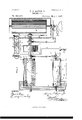
- Figure l is a conventional illustration of the sending apparatus, which also serves as the receiving apparatus.
- Fig. 2 is a face View of the character-disk, and Figs. 3 and 4: are respectively a side and sectional view of the motor.
- M represents an alternating-current motor, or being its armatureshaft, upon which is mounted a commutator C.
- the commutator consists of a cylinder whose surface is, for the most part, insulating material, but which contains a series of contact-pieces a b c, &c., one for each character which the instrument is designed to transmit and arranged spirally and at equal distances apart. These contacts are all connected internally with a continuous metal ring C, upon which a brush C bears.
- Ad jacent to the commutator is mounted a series of brushes a b c, 800., corresponding, respectively, with the series of contacts a I) c and Serial No. 599,624. (No model.)
- Shaft m of the motor extends into a dark chamber D and carries upon its extremity a transparent disk D, around the edge of which is painted or otherwise portrayed a complete set of characters. These characters are regularly spaced apart and correspond, respectively, with the contacts a b c of the commutator.
- a drum D mounted upon a vertical axis and adapted to carry a photographic sensitive film.
- Eis a closed dark box having a perforated screen 6 e at each end and containing a polariscope consisting of two Nicols prisms e and c Between the prisms is a tube 6 having glass ends and filled with bisulfid of carbon or other substance possessing magnetic optical rotary power.
- the tube and prisms are located in line between the apertures in the two screens, and the row of charactors on the disk D crosses the same line.
- At F is represented a source of light, which, as will be understood, may be of any character.
- the polarizing-prism c and analyzer e are set at right angles to each other, so that ordinarily no light can pass through them.
- a helix 6 Around the tube is coiled a helix 6 connected in an electric circuit, as will be here inafter described.
- a current flowing through this helix creates a magnetic field which includes the bisulfid of carbon and causes it to rotate the beam of polarized light, so that all or nearly all of it passes through the analyzer e and through the particular portion of the disk D that may be at the same time presented to the aperture in the screen (2, in consequence of which the letter or character upon this part of the disk is photographed upon the sensitive film.
- This whole device consisting of the polariscope and the tube of bisulfid of carbon, with its helix, constitutes an electrically-operated shutter for controlling the passage of light through the disk to the sensitive film.
- the shutter is located in the same radial plane with the set of brushes a b c, &O., so that when a brush connects with a contact a b c, &c., the corresponding letter on the disk will be presented opposite the aperture.
- the motor-shaft m Upon the motor-shaft m are also mounted two eccentrics f and f, the latter of which moves a pawl g once for each rotation of the shaft and thereby sets forward the drum D one letter-space.
- Adjacent to the shaft m is a counter-shaft 0, carrying a metallic roller R and driven by means of a pawl and ratchet o 0 from the eccentric f. At the end of each rotation of shaft m shaft 0 is moved forward one notch.
- the roller R is adapted to receive a strip of paper P, in which the message to be sent is indicated by punchings p.
- the punchings are all alike in size and shape, and a particular character which a punching indicates is determined by its position in the strip of paper in a transverse direction, its position in alongitudinal direction determining the time at which the character is transmitted.
- Adjacent to the roller is mounted a series of brushes 0.
- the switch 5 is put into the position shown in the drawings.
- the strip of paper having the message punched therein is adjusted to the roller R and the motors at the ends of the line are started, it being understood for the present that they run in synchronism and in step.
- the brush a is the first one to make contact with the roller and that it represents the letter A. This contact is continued while the commutator G is making one complete rotation, some time during which its brush or makes momentary connection'with the contact a.
- the disk D presents the letter A opposite the shutter-aperture, and as a momentary current is then flowing from battery S through switch 8 wire 8, brush 8, roller R, brush a wire w, connected therewith, brush a, contact a, in-
- a beam of light may pass through the disk D and photograph the letter A upon the sensitive film carried by the drum D but as this is the sending end it is'not necessary that the photographing should be done, and consequently a shuntcircuit 6 maybe closed, or a permanent screen maybe placed across the opening in the screen 6-, or any other means may be adopted for preventing photography at the sending end.
- the momentary impulse passes over the line, and, assuming the apparatus of Fig.
- My invention is not limited in any manner to the means for operating the motors on the line in synchronism. They may be operated by an alternating current traversing the main line from a single source, but I prefer to supply each motor fromalocal battery and transform the direct current so produced into an alternating current of the same number of alternations per second for each motor by means of a harmonic vibrator, such as is used in Grays harmonic multiple telegraphy, which is described on page No. 847 of Prescotts Electricity and the Electric Telegraph, published by D. Appleton & 00., 1882. It is unnecessary to here describe specifically this vibrator, or to describe any other particular way of operating the motors synchronously, it being understood that any available means may be adopted.
- This motor is an ordinary alternating type, except that its field-magnets are mounted in a circular frame Q, which maybe ICO shifted on. its axis within a fixed ring Q. This ring is provided with side flanges q to hold the field-magnet in place.
- the field-magnet may be given any circular position and fixed in any particular position by means of a set-screw g
- the position of the armature at the end of each rotation can be shifted until it has reached the desired position, as ascertained by the letter-plate connected directly to the armature-shaft, at which position the field will be fixed by the set-screw.
- the armature and letter-plate can be set forward or backward to any desired position. To illustrate this, suppose a letter (say A, prearranged between operators) is telegraphed many times in succession and it is ascertained at the receiving end that the letter P is being photographed. The field-magnet of the receivingmotor must then be shifted through the angle from P to A..
- shutter described herein is preferred, because it does not involve the movement of ponderous matter in which inertia would prevent rapid act-ion, but it will be understood that the invention, broadly considered, comprehends the use of any mechanical or other shutter operated by an impulse of current.
- the operation of sending and receiving messages at the same time and of sending and receiving a number of mes sages at the same time by this instrument may be effected by comparatively simple mechanism in addition to that herein described, and I have already devised such mechanism, which I may make the subject of one or more separate applications.
- a telegraphic apparatus comprising a mechanical pattern of a character or series of characters, located at the sending end, means for moving said pattern, means for presenting the character or series of characters corresponding to the pattern at a predetermined point at the receiving end, a source of light, ashutter forcontrollin g the admission of light to the said character or series of characters at said predetermined point, an electric circuit including a commutator and said shutter and means under the control of said movin g pattern for manipulating the said electric circuit to operate the shutter and thereby admit light to the said character or series of characters corresponding to the pattern.
Description
(No Model.) 2Sheets-Sheet1.
O.F.EATON,J12
TELEGRAPHY.
No. 581,815. Patented May 4,1897.
WITNESSES:
m: norm: runs :0, wow-mum. wuumarm a c.
2 t 8 6 h S .W e e h S 2 r J N O T A E h 0 (No Model.)
TELEGBAPHY.
No. 581,815. Patented May 4,1897.
1: mums PETERS comnoYo-m'mn wnsnlu-sros. o c,
UNlTE rates r FFICE.
CHARLES F. EATON, JR, OF SANTA BARBARA, CALIFORNIA, ASSIGNOR OF ONE-THIRD TO CHARLES F. EATON, SR., OF SAME PLACE.
TELEG RAPHY.
SPECIFICATION forming part of Letters Patent No. 581,815, dated May 4, 1897.
Application filed July 18, 1896.
To all whom it may concern.-
Be it known that 1, CHARLES F. EATON, Jr. a citizen of the United States, residing at Santa Barbara, in the county of Santa Barbara and State of California, have invented certain new and useful Improvements in Telegraphy, of which the following is a full, clear, and exact description.
This invention relates to automatic telegraphy, the objects being the saving of labor, the prevention of mistakes in transmitting and receiving, and the rapid transmission of intelligence.
The invention com prehends the employment of synchronous alternating-current motors and instantaneous photography as the means for carrying out the said objects.
The message to be sent is punched in a strip of paper, which is then placed in the sending instrument and the characters successively sent over theline. An alternating-current electric motor drives the sending instrument, and at the receiving end a disk containing a set of characters is rotated by a similar motor, and aparticular character on it is brought into position to be photographed simultaneously with the receipt of an impulse from the sending end, which operates a shutter to accomplish the photographing of the letter or character presented.
In the accompanying drawings, Figure l is a conventional illustration of the sending apparatus, which also serves as the receiving apparatus. Fig. 2 is a face View of the character-disk, and Figs. 3 and 4: are respectively a side and sectional view of the motor.
Referring to Fig. 1, M represents an alternating-current motor, or being its armatureshaft, upon which is mounted a commutator C. The commutator consists of a cylinder whose surface is, for the most part, insulating material, but which contains a series of contact-pieces a b c, &c., one for each character which the instrument is designed to transmit and arranged spirally and at equal distances apart. These contacts are all connected internally with a continuous metal ring C, upon which a brush C bears. Ad jacent to the commutator is mounted a series of brushes a b c, 800., corresponding, respectively, with the series of contacts a I) c and Serial No. 599,624. (No model.)
resting upon the surface of the commutator in such positions that as the commutator r0- tatcs contact will successively be made between them and the contacts a b c, &e., re spectively, one complete'rotation of the corn mutator serving to bring all of the contacts into connection with the brushes. Shaft m of the motor extends into a dark chamber D and carries upon its extremity a transparent disk D, around the edge of which is painted or otherwise portrayed a complete set of characters. These characters are regularly spaced apart and correspond, respectively, with the contacts a b c of the commutator. Directly behind the disk D in the dark chamber is a drum D mounted upon a vertical axis and adapted to carry a photographic sensitive film. V
Eis a closed dark box having a perforated screen 6 e at each end and containing a polariscope consisting of two Nicols prisms e and c Between the prisms is a tube 6 having glass ends and filled with bisulfid of carbon or other substance possessing magnetic optical rotary power. The tube and prisms are located in line between the apertures in the two screens, and the row of charactors on the disk D crosses the same line. At F is represented a source of light, which, as will be understood, may be of any character. The polarizing-prism c and analyzer e are set at right angles to each other, so that ordinarily no light can pass through them.
Around the tube is coiled a helix 6 connected in an electric circuit, as will be here inafter described. A current flowing through this helix creates a magnetic field which includes the bisulfid of carbon and causes it to rotate the beam of polarized light, so that all or nearly all of it passes through the analyzer e and through the particular portion of the disk D that may be at the same time presented to the aperture in the screen (2, in consequence of which the letter or character upon this part of the disk is photographed upon the sensitive film. This whole device, consisting of the polariscope and the tube of bisulfid of carbon, with its helix, constitutes an electrically-operated shutter for controlling the passage of light through the disk to the sensitive film.
The shutter is located in the same radial plane with the set of brushes a b c, &O., so that when a brush connects with a contact a b c, &c., the corresponding letter on the disk will be presented opposite the aperture. Upon the motor-shaft m are also mounted two eccentrics f and f, the latter of which moves a pawl g once for each rotation of the shaft and thereby sets forward the drum D one letter-space.
Adjacent to the shaft m is a counter-shaft 0, carrying a metallic roller R and driven by means of a pawl and ratchet o 0 from the eccentric f. At the end of each rotation of shaft m shaft 0 is moved forward one notch. The roller R is adapted to receive a strip of paper P, in which the message to be sent is indicated by punchings p. The punchings are all alike in size and shape, and a particular character which a punching indicates is determined by its position in the strip of paper in a transverse direction, its position in alongitudinal direction determining the time at which the character is transmitted. Adjacent to the roller is mounted a series of brushes 0. 17 0 850., corresponding, respectively, with the brushes a b c and electrically connected therewith by the respective wires w. The brushes bear against the strip of paper,which normally insulates them from the roller R. The roller is in connection with a source of electricity S by means of brush 3 and wire 8.
' Each time the paper F moves forward one step one of the perforations p is presented to one of the brushes a b 0 which allows the particular brush to come in contact with the roller and thus send current from the source S through the corresponding wire to to the corresponding brush in the series a Z) c. This condition exists while the commutator O is making one complete rotation, during which period, at some instant, the particular brush in the series a b 0 will make contact with its corresponding contact on the surface of the commutator O, and thus establish a circuit to brush 0 from which point a wire 5 carries the current to the helix e and thus by wire 6 to the distant or receiving station.
The operation is as follows: At the sending end the switch 5 is put into the position shown in the drawings. The strip of paper having the message punched therein is adjusted to the roller R and the motors at the ends of the line are started, it being understood for the present that they run in synchronism and in step. Let us assume that the brush a is the first one to make contact with the roller and that it represents the letter A. This contact is continued while the commutator G is making one complete rotation, some time during which its brush or makes momentary connection'with the contact a. At the same instant the disk D presents the letter A opposite the shutter-aperture, and as a momentary current is then flowing from battery S through switch 8 wire 8, brush 8, roller R, brush a wire w, connected therewith, brush a, contact a, in-
ternal conductor to ring E brush C wire 3, helix c and wire 6 to line, a beam of light may pass through the disk D and photograph the letter A upon the sensitive film carried by the drum D but as this is the sending end it is'not necessary that the photographing should be done, and consequently a shuntcircuit 6 maybe closed, or a permanent screen maybe placed across the opening in the screen 6-, or any other means may be adopted for preventing photography at the sending end. The momentary impulse, however, passes over the line, and, assuming the apparatus of Fig. 1 to now represent the receiving instru ment, the switch 5 being thrown to its other position, the current travels along wire 7, wire 5, helix c and wire 6 to the return-circuit, the roller R and commutator C being out of use, although they maybe running. As the motors are in synchronism and in step, theletter A will be opposite the aperture at the moment the current traverses the helix of the shutter, and light then admitted photographs the letter upon the film. After all of the con tacts on the commutator have passed the brushes there is a short blank space on the commutator and on the letter disk, which gives an opportunity for the eccentrics f and f to move their respective ratchets and thus set the paper-roller forward to the next character and the drum D forward one letterspace. In the next rotation of the commutator 0 another impulse is sent over the line, and simultaneously with it the character on the disk D which corresponds with it is presented at the aperture and photographed. Thus the-operation continues to the end of the message, after which the sensitive film may be removed from the drum D and developed by any process.
My invention is not limited in any manner to the means for operating the motors on the line in synchronism. They may be operated by an alternating current traversing the main line from a single source, but I prefer to supply each motor fromalocal battery and transform the direct current so produced into an alternating current of the same number of alternations per second for each motor by means of a harmonic vibrator, such as is used in Grays harmonic multiple telegraphy, which is described on page No. 847 of Prescotts Electricity and the Electric Telegraph, published by D. Appleton & 00., 1882. It is unnecessary to here describe specifically this vibrator, or to describe any other particular way of operating the motors synchronously, it being understood that any available means may be adopted. As a means, however, for getting the motors into step or of insuring that a certain letter on the disk shall be opposite the aperture of the shutter in all of the motors at the same time I have devised a special form of motor. (Shown in Figs. 3 and 4:.) This motor is an ordinary alternating type, except that its field-magnets are mounted in a circular frame Q, which maybe ICO shifted on. its axis within a fixed ring Q. This ring is provided with side flanges q to hold the field-magnet in place. By means of a crank q the field-magnet may be given any circular position and fixed in any particular position by means of a set-screw g As the relative speed of the armature to the field is constant, the position of the armature at the end of each rotation can be shifted until it has reached the desired position, as ascertained by the letter-plate connected directly to the armature-shaft, at which position the field will be fixed by the set-screw. Thus the armature and letter-plate can be set forward or backward to any desired position. To illustrate this, suppose a letter (say A, prearranged between operators) is telegraphed many times in succession and it is ascertained at the receiving end that the letter P is being photographed. The field-magnet of the receivingmotor must then be shifted through the angle from P to A..
The form of shutter described herein is preferred, because it does not involve the movement of ponderous matter in which inertia would prevent rapid act-ion, but it will be understood that the invention, broadly considered, comprehends the use of any mechanical or other shutter operated by an impulse of current. The operation of sending and receiving messages at the same time and of sending and receiving a number of mes sages at the same time by this instrument may be effected by comparatively simple mechanism in addition to that herein described, and I have already devised such mechanism, which I may make the subject of one or more separate applications.
Having thus described my invention, I claim- 1. A telegraphic apparatus comprising a mechanical pattern of a character or series of characters, located at the sending end, means for moving said pattern, means for presenting the character or series of characters corresponding to the pattern at a predetermined point at the receiving end, a source of light, ashutter forcontrollin g the admission of light to the said character or series of characters at said predetermined point, an electric circuit including a commutator and said shutter and means under the control of said movin g pattern for manipulating the said electric circuit to operate the shutter and thereby admit light to the said character or series of characters corresponding to the pattern.
' 2. In telegraphy, the combination of a rotatin g character-plate at the receiving end of the line, a rotating commutator at the sending end moving in unison therewith and provided with contacts corresponding in position respectively with the characters on the character-plate, a camera at the receiving end arranged to photograph the characters on the character-plate, electromagnetic apparatus for operating the shutter of the camera, and an electric circuit including the electromagnetic shutter apparatus and adapted to be closed by any of the contacts on the commu tator, substantially as described.
3. In telegraphy, the combination of a rotating character-plate at the receiving end of the line, a rotating commutator at the sending end, moving in unison therewith, contacts on the commutator corresponding in position respectively with the characters on the character-plate, a series of fixed contacts corresponding respectively to those of the commutator, a circuit-closer consisting of a series of fingers electrically connected respectively with said fixed contacts, means for connecting one of said fingers with a sourceof electricity during the time the commutator is making each complete rotation, a camera arranged so that the characters on the charac ter-plate will successively pass its aperture, and means whereby the impulses of current passing through the circuit-closer and comm utator will operate the shutter of the cam era.
In testimony whereof I subscribe my signature in presence of two witnesses.
CHARLES F. EATON, JR.
\Vituesses:
FRANK S. OBER, WM. A. ROSENBAUM.
Publications (1)
| Publication Number | Publication Date |
|---|---|
| US581815A true US581815A (en) | 1897-05-04 |
Family
ID=2650491
Family Applications (1)
| Application Number | Title | Priority Date | Filing Date |
|---|---|---|---|
| US581815D Expired - Lifetime US581815A (en) | eaton |
Country Status (1)
| Country | Link |
|---|---|
| US (1) | US581815A (en) |
Cited By (10)
| Publication number | Priority date | Publication date | Assignee | Title |
|---|---|---|---|---|
| US2578025A (en) * | 1949-11-18 | 1951-12-11 | Alfred A Sweeny | Printing telegraph system |
| US2620394A (en) * | 1943-06-11 | 1952-12-02 | Georges Valensi | High-speed telegraphic system |
| US2725803A (en) * | 1947-06-07 | 1955-12-06 | Cecil L Tansel | Photographic composing apparatus |
| US2787654A (en) * | 1948-07-29 | 1957-04-02 | Walter E Peery | Electronic photo-typecomposing system |
| US2790362A (en) * | 1946-12-26 | 1957-04-30 | Graphic Arts Res Foundation In | Photo composing machine |
| US2831410A (en) * | 1950-10-09 | 1958-04-22 | Lester M Walden | Equipment for type setting |
| US2896523A (en) * | 1947-06-07 | 1959-07-28 | Harris Intertype Corp | Phototypograph |
| US2974568A (en) * | 1957-02-15 | 1961-03-14 | Bell Telephone Labor Inc | Light modulator |
| US3182574A (en) * | 1963-03-05 | 1965-05-11 | Ibm | Display apparatus |
| US3657978A (en) * | 1969-10-06 | 1972-04-25 | Zdzislaw Zakrzewski | Method and apparatus for optical printing |
-
0
- US US581815D patent/US581815A/en not_active Expired - Lifetime
Cited By (10)
| Publication number | Priority date | Publication date | Assignee | Title |
|---|---|---|---|---|
| US2620394A (en) * | 1943-06-11 | 1952-12-02 | Georges Valensi | High-speed telegraphic system |
| US2790362A (en) * | 1946-12-26 | 1957-04-30 | Graphic Arts Res Foundation In | Photo composing machine |
| US2725803A (en) * | 1947-06-07 | 1955-12-06 | Cecil L Tansel | Photographic composing apparatus |
| US2896523A (en) * | 1947-06-07 | 1959-07-28 | Harris Intertype Corp | Phototypograph |
| US2787654A (en) * | 1948-07-29 | 1957-04-02 | Walter E Peery | Electronic photo-typecomposing system |
| US2578025A (en) * | 1949-11-18 | 1951-12-11 | Alfred A Sweeny | Printing telegraph system |
| US2831410A (en) * | 1950-10-09 | 1958-04-22 | Lester M Walden | Equipment for type setting |
| US2974568A (en) * | 1957-02-15 | 1961-03-14 | Bell Telephone Labor Inc | Light modulator |
| US3182574A (en) * | 1963-03-05 | 1965-05-11 | Ibm | Display apparatus |
| US3657978A (en) * | 1969-10-06 | 1972-04-25 | Zdzislaw Zakrzewski | Method and apparatus for optical printing |
Similar Documents
| Publication | Publication Date | Title |
|---|---|---|
| US581815A (en) | eaton | |
| US1910540A (en) | Secret television | |
| US582157A (en) | Charles f | |
| US463852A (en) | Synchronous telegraph | |
| US282295A (en) | field | |
| US2262141A (en) | Phasing mechanism | |
| US3546403A (en) | Motion picture apparatus with improved impulse transmitter contact structure | |
| US368858A (en) | sheehy | |
| US566985A (en) | Telegraphy | |
| US282294A (en) | field | |
| US1176148A (en) | Telegraphy. | |
| US316693A (en) | Beegh | |
| US225395A (en) | Electro-magnetic motor | |
| US728254A (en) | Facsimile-telegraph. | |
| US689753A (en) | Multiplex printing-telegraph. | |
| US1942588A (en) | Telegraph regenerative repeater | |
| US939339A (en) | Electric transmission of messages. | |
| US282297A (en) | field | |
| US848221A (en) | Telegraphy. | |
| US711743A (en) | Telautomotor. | |
| US282296A (en) | Dynamo-telegraphy | |
| US577534A (en) | muirhead | |
| US1343754A (en) | Apparatus for teaching codes as used in telegraphy | |
| US823206A (en) | Telegraph-transmitter. | |
| US26003A (en) | Improvement in telegraphic machines |