US581141A - William g - Google Patents
William g Download PDFInfo
- Publication number
- US581141A US581141A US581141DA US581141A US 581141 A US581141 A US 581141A US 581141D A US581141D A US 581141DA US 581141 A US581141 A US 581141A
- Authority
- US
- United States
- Prior art keywords
- bin
- sand
- tube
- gate
- appliances
- Prior art date
- Legal status (The legal status is an assumption and is not a legal conclusion. Google has not performed a legal analysis and makes no representation as to the accuracy of the status listed.)
- Expired - Lifetime
Links
- 239000004576 sand Substances 0.000 description 26
- 238000010276 construction Methods 0.000 description 6
- 238000007599 discharging Methods 0.000 description 2
- 239000010426 asphalt Substances 0.000 description 1
- 239000004020 conductor Substances 0.000 description 1
- 239000000463 material Substances 0.000 description 1
- 239000000615 nonconductor Substances 0.000 description 1
Images
Classifications
-
- B—PERFORMING OPERATIONS; TRANSPORTING
- B65—CONVEYING; PACKING; STORING; HANDLING THIN OR FILAMENTARY MATERIAL
- B65F—GATHERING OR REMOVAL OF DOMESTIC OR LIKE REFUSE
- B65F1/00—Refuse receptacles; Accessories therefor
- B65F1/12—Refuse receptacles; Accessories therefor with devices facilitating emptying
Definitions
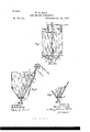
- Figure 1 shows a side elevation of-my sandbin and appliances.
- Fig. 2 shows a vertical section of the same, taken on line A B, Fig. 1.
- Fig. 3 shows a partial vertical section of a modified form of construction.
- 1 indicates the sand-bin, which is of comparatively large dimensions at its upper end and tapered to small dimensions at its lower end and having a narrow bottom 2.
- the bin is provided with a series of discharge-spouts 8, 4, and 5, adapted to discharge into a mixing or measuring box 6 and each controlled by a separate Spouts or chutes 3 and 5 draw from the outer ends of the bin, while the chute 4 draws from the center portion of the contents of the bin.
- a conductor tube or pipe 7 Extending through the interior of the bin and removed a considerable distance inwardly from the most adjacent wall of the bin is provided a conductor tube or pipe 7.
- This tube is provided with an extension 7 outside of the bottom of the bin and the lower end of the tube is controlled by a slide or gate 1).
- the upper end of the tube 7 is preferably slightly enlarged I and is located in a position so that the sand brought up by the elevating-carrier 8 will be discharged into the upper end 7 of the tube.
- the tube is also provided adjacent to its upper end with a slide or gate 7, which is operated by means of a pivoted lever-handle 9, connected with the end of the gate by a connecting-rod 10, extending through the wall of the bin.
- This bin with its appliances, is particularly intended for use in mixing sand with asphalt the sand will overflow the end of the tube and drop into the bin, and the bin in practice is maintained more or less full of heated sand.
- the valve or gate 7 is open and the gate 1) closed the tube 7 will entirely fill with heated sand, and after it is entirely full the sand will then overflow the upper end of the tube and fall into the bin.
- sand of the desired temperature may be obtained by means of this sand-bin and its appliances, or the sand may be tempered and brought to the desired temperature as follows: The sand which has remained in the bin for some time will be more or less cooled, while the sanddischarge from the elevator 8 will be of the highest temperature of any at the disposal of the operator of the appliances.
- the mixing-box 6 may be filled by drawing through the tube 4.
- cooler sand it may be had from either of the tubes 3 or 5, which draw from the outer sides or ends of the bin.
- the gate 1 might be left open and the gate 7 c operated by a lever to supply the sand as it comes directly from the carrier, excepting, perhaps, what might be contained in the upper flaring end of the tube.
- the sand may be tempered to a nicety and thereby the best results attained.
- the tube 7 may, if desired, be constructed of some material which isa non-conductor of heat, or substantially so.
- the tube :0 is used in lieu of the tube 7 of the previous construction, and this tube is terminated,as shown, a short distance above the lower end or bottom of the bin.
- a tube-holder g which secures the tube to the wall of the bin.
- the tube a may or may not be provided with a gate like 7ot' the previouslydescribed construction.
- the sand-discharge consists in part of the heated sand coming through the tube 00, while a part of the discharge will come from the body of the bin and surround and mix as it passes through the discharge-tube section cc into the mixing-box.
- a sand-bin having a series of dischargeopenings in its bottom, means for discharging sand into the top of the bin, a conveying-tube extending through the body of the bin from the source of supply at the top of the bin to the bottom of the bin and provided with a gate for independentlycontrolling the flow of sand in the tube, substantially as set forth.
Landscapes
- Engineering & Computer Science (AREA)
- Mechanical Engineering (AREA)
- Road Paving Machines (AREA)
Description
(No Model.)
W. G. ROOT.
SAND BIN AND APPLIANCES.
' .No. 581,141. Patented Apr. 20,1897.
JNVENTOR Wzzwzmsms MA'W V am 4 JM y' 1 frzm z qrjs.
- slide or gate a.
UNITE STATES ATENT FFICE.
WILLIAM G. ROOT, OF TOLEDO, OHIO, ASSIGNOR TO THE WARREN-SOI-IARF ASPHALT PAVING COMPANY, OF NEIV YORK, N. Y.
SAN D-BIN AND APPLIANCES.
SPECIFICATION forming part of Letters Patent No. 581 ,141, dated April 20, 1897. Application filed February 3, 1897. Serial No. 621,902. (No model.)
To aZZ whom it may concern.-
Be it known thatl, WILLIAM G. RooT, of Toledo, in the county of Lucas and State of Ohio, have invented certain new and useful Improvements in Sand-Bins and Appliances; and I do hereby declare that the following is a full, clear, and exact description of the invention, which will enable others skilled in the art to which it 'appertains to make and use the same, reference being had to the accompanying drawings, and to the letters and figures of reference marked thereon, which form part of this specification.
Figure 1 shows a side elevation of-my sandbin and appliances. Fig. 2 shows a vertical section of the same, taken on line A B, Fig. 1. Fig. 3 shows a partial vertical section of a modified form of construction.
Referring to the reference letters and numbers in a more particular description of the device, 1 indicates the sand-bin, which is of comparatively large dimensions at its upper end and tapered to small dimensions at its lower end and having a narrow bottom 2. At the lower end or bottom the bin is provided with a series of discharge-spouts 8, 4, and 5, adapted to discharge into a mixing or measuring box 6 and each controlled by a separate Spouts or chutes 3 and 5 draw from the outer ends of the bin, while the chute 4 draws from the center portion of the contents of the bin. Extending through the interior of the bin and removed a considerable distance inwardly from the most adjacent wall of the bin is provided a conductor tube or pipe 7. This tube is provided with an extension 7 outside of the bottom of the bin and the lower end of the tube is controlled by a slide or gate 1). The upper end of the tube 7 is preferably slightly enlarged I and is located in a position so that the sand brought up by the elevating-carrier 8 will be discharged into the upper end 7 of the tube. The tube is also provided adjacent to its upper end with a slide or gate 7, which is operated by means of a pivoted lever-handle 9, connected with the end of the gate by a connecting-rod 10, extending through the wall of the bin.
This bin, with its appliances, is particularly intended for use in mixing sand with asphalt the sand will overflow the end of the tube and drop into the bin, and the bin in practice is maintained more or less full of heated sand. In case the valve or gate 7 is open and the gate 1) closed the tube 7 will entirely fill with heated sand, and after it is entirely full the sand will then overflow the upper end of the tube and fall into the bin.
In drawing sand into the mixing-box 6 sand of the desired temperature may be obtained by means of this sand-bin and its appliances, or the sand may be tempered and brought to the desired temperature as follows: The sand which has remained in the bin for some time will be more or less cooled, while the sanddischarge from the elevator 8 will be of the highest temperature of any at the disposal of the operator of the appliances. In case the sand in the center of the body of the bin is just the right temperature the mixing-box 6 may be filled by drawing through the tube 4. In case cooler sand is desired it may be had from either of the tubes 3 or 5, which draw from the outer sides or ends of the bin. In case hotter sand than is to be had from either of the tubes 3, 4, or 5 is desired it is obtained by drawing through the tube 7 either that portion of the sand which is contained in the tube 7 or the sand as it is discharged from the carrier. This may be done by operating either the gate Z) or the gate 7, or both, as may be desired. In case a very quick supply of the hottest sand is desired the apparatus might be used with the gate 7 in open position, which would keep the tube 7 full of sand and where the quantity which the tube would contain would be at once accessible by opening the gate 1). In case a more medium fiow of sand is desired the gate 1) might be left open and the gate 7 c operated by a lever to supply the sand as it comes directly from the carrier, excepting, perhaps, what might be contained in the upper flaring end of the tube. By
means of this arrangement of bin and appliances the sand may be tempered to a nicety and thereby the best results attained.
The tube 7 may, if desired, be constructed of some material which isa non-conductor of heat, or substantially so.
In the modified form of construction shown in Fig. 3 the tube :0 is used in lieu of the tube 7 of the previous construction, and this tube is terminated,as shown, a short distance above the lower end or bottom of the bin. In order to hold the lower end of the tube stationary and removed from the side of the bin in a position directly over the discliarge-opening in the bottom, there is provided a tube-holder g, which secures the tube to the wall of the bin. In connection with this construction there is employed a small section x of tube secured to the bin and projecting ashort distance to direct the flow of sand into the mixing-box, and the opening at the lower end of the tube a: is controlled by a slide or gate m similar to those heretofore described. At the upper end the tube a; may or may not be provided with a gate like 7ot' the previouslydescribed construction. In this modified form of construction when the gate m is open the sand-discharge consists in part of the heated sand coming through the tube 00, while a part of the discharge will come from the body of the bin and surround and mix as it passes through the discharge-tube section cc into the mixing-box.
\Vhat I claim as new, and desire to secure by Letters Patent, is
1. A sand-bin having a series of dischargeopenings in its bottom, means for discharging sand into the top of the bin, a conveying-tube extending through the body of the bin from the source of supply at the top of the bin to the bottom of the bin and provided with a gate for independentlycontrolling the flow of sand in the tube, substantially as set forth.
2. The combination with a sand-bin having a series of discharge-openings at its bottom and gates for controlling the same, of means for supplying sand to the bin discharging in the top of the bin, a tube extending through the body of the bin from a point at the top where it will receive the supply, to a point at the bottom of the bin and means for controlling the fiow of sand through the tube, substantially as set forth.
In witness whereof I have affixed my signature in presence of two witnesses.
M. G. ROOT.
\Vitnesses:
WM. G. BURDETTE, A. P. BRIGGS.
Publications (1)
| Publication Number | Publication Date |
|---|---|
| US581141A true US581141A (en) | 1897-04-20 |
Family
ID=2649818
Family Applications (1)
| Application Number | Title | Priority Date | Filing Date |
|---|---|---|---|
| US581141D Expired - Lifetime US581141A (en) | William g |
Country Status (1)
| Country | Link |
|---|---|
| US (1) | US581141A (en) |
-
0
- US US581141D patent/US581141A/en not_active Expired - Lifetime
Similar Documents
| Publication | Publication Date | Title |
|---|---|---|
| US2723838A (en) | Apparatus for mixing and homogenizing pulverulent or fine-grained materials | |
| US1224656A (en) | Concrete-mixer. | |
| US475575A (en) | Apparatus for the manufacture of salt | |
| US332731A (en) | Draft-tube for soda-water | |
| US799808A (en) | Sand-blast apparatus. | |
| US1101574A (en) | Liquid mixing and filling apparatus. | |
| US977372A (en) | Funnel. | |
| US562892A (en) | Attachment for force-feed faucets | |
| US2267978A (en) | Apparatus for applying surfacing material to roads | |
| US414397A (en) | Apparatus for tapping molten metal | |
| US561718A (en) | Measuring-can for dispensing liquids | |
| US208645A (en) | Improvement in self-measuring faucets | |
| US481080A (en) | Grain cut-off | |
| US299170A (en) | Funnel | |
| US919074A (en) | Mixing-machine. | |
| US739489A (en) | Siphon. | |
| US950372A (en) | Closure. | |
| US540844A (en) | Faucet | |
| US2159689A (en) | Weigh bucket | |
| US805719A (en) | Machine for pouring filling material in crevices. | |
| US1015537A (en) | Apparatus for charging glass-molds. | |
| US162223A (en) | Improvement in nozzles for oil-cans | |
| US1364533A (en) | Feeding device for pulverulent fuel | |
| US580769A (en) | Portable glue | |
| US637118A (en) | Insect-powder duster. |