US5803528A - Truck cover - Google Patents
Truck cover Download PDFInfo
- Publication number
- US5803528A US5803528A US08/675,573 US67557396A US5803528A US 5803528 A US5803528 A US 5803528A US 67557396 A US67557396 A US 67557396A US 5803528 A US5803528 A US 5803528A
- Authority
- US
- United States
- Prior art keywords
- arm
- arms
- truck
- base member
- elongate
- Prior art date
- Legal status (The legal status is an assumption and is not a legal conclusion. Google has not performed a legal analysis and makes no representation as to the accuracy of the status listed.)
- Expired - Fee Related
Links
- 230000007704 transition Effects 0.000 claims description 5
- 239000000463 material Substances 0.000 claims description 3
- 230000007246 mechanism Effects 0.000 description 2
- 239000007787 solid Substances 0.000 description 2
- 239000004698 Polyethylene Substances 0.000 description 1
- 229910000831 Steel Inorganic materials 0.000 description 1
- 239000012190 activator Substances 0.000 description 1
- 239000003292 glue Substances 0.000 description 1
- 238000007689 inspection Methods 0.000 description 1
- 238000005461 lubrication Methods 0.000 description 1
- -1 polyethylene Polymers 0.000 description 1
- 229920000573 polyethylene Polymers 0.000 description 1
- 230000002265 prevention Effects 0.000 description 1
- 239000010959 steel Substances 0.000 description 1
- 230000000007 visual effect Effects 0.000 description 1
- 238000003466 welding Methods 0.000 description 1
Images


Classifications
-
- B—PERFORMING OPERATIONS; TRANSPORTING
- B60—VEHICLES IN GENERAL
- B60J—WINDOWS, WINDSCREENS, NON-FIXED ROOFS, DOORS, OR SIMILAR DEVICES FOR VEHICLES; REMOVABLE EXTERNAL PROTECTIVE COVERINGS SPECIALLY ADAPTED FOR VEHICLES
- B60J7/00—Non-fixed roofs; Roofs with movable panels, e.g. rotary sunroofs
- B60J7/08—Non-fixed roofs; Roofs with movable panels, e.g. rotary sunroofs of non-sliding type, i.e. movable or removable roofs or panels, e.g. let-down tops or roofs capable of being easily detached or of assuming a collapsed or inoperative position
- B60J7/085—Non-fixed roofs; Roofs with movable panels, e.g. rotary sunroofs of non-sliding type, i.e. movable or removable roofs or panels, e.g. let-down tops or roofs capable of being easily detached or of assuming a collapsed or inoperative position winding up, e.g. for utility vehicles
Definitions
- the present invention relates to truck cover systems, and more particularly to a truck cover system for maintaining a cover in close proximity to a container.
- Flexible covers are placed over open truck-borne containers for many reasons including protection of the contents of the container and prevention of the contents from being blown out of the container while the truck is in transit.
- containers can be covered by manually operated cover mechanisms, mechanical devices are known that assist in positioning a cover over an open truck container.
- One type of mechanical covering device includes telescopic arms comprising two nested arm segments that are extended or retracted by piston-like actuators as the arms are pivoted fore and aft to pull a cover over or retract a cover from the top of a container.
- the nested arm segments must remain relatively straight and undented to telescope properly and not bind. When damaged, this type of telescopic arm is not readily useable or repairable.
- a truck cover system is provided that is durable and easily maintained.
- the truck cover system is securable to a support structure and includes a pair of arms which move from a first position to a second position to draw a flexible cover over an upwardly open container having an opening defined by an upper edge.
- the truck cover system includes a pair of nonlinear arms, movable in unison from a first position to a second position.
- Each of the arms includes an elongate base member slidably engaged with an elongate extension member wherein the extension member has a first elongate portion disposed at an obtuse angle with respect to a second elongate portion.
- the second elongate portion of the extension member is substantially parallel, noncoaxial, and in slidable engagement with the base member.
- the first elongate portion of the extension member is secured to a first end of the flexible cover.
- the truck cover system further includes first and second actuators associated with each of the nonlinear arms to move the arm from the first position to the second position.
- FIG. 1 is a side view of a truck cover system illustrating arm movement to cover a truck container
- FIG. 2 is detailed view of arm elements of the truck cover system of FIG. 1;
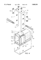
- FIG. 3 is a front sectional view of a first retainer
- FIG. 4 is a perspective partially exploded view of the first retainer of FIG. 3.
- FIG. 5 is a front sectional view of a second retainer.
- FIG. 6 is a view of the truck cover system illustrating both arms of the apparatus.
- FIG. 1 and FIG. 6 illustrate a durable and easily maintainable truck cover system.
- the truck cover system includes arms which provide easy visual and mechanical access to system components for rapid inspection and replacement thereof.
- the arms are extendable to enable containers of different sizes to be covered, as well as to control a travel path for a flexible cover.
- the structure of the arms allows long and short containers to be completely covered. Also, the arms may be adjusted to accommodate some arm and container distortion. It will be appreciated that the arms may be linear or nonlinear.
- FIGS. 1 and 2 illustrate a truck cover system 10 secured to a truck frame 12 by a support structure 14.
- the device is symmetrical, therefore for simplicity sake, only a single side is shown in the drawings, though it should be understood that the other side contains similar structure and operates in a similar manner.
- the truck cover system 10 is capable of drawing a flexible cover 16 having a first end 18 and a second end 20 over a container 21 having an opening 22 defined by an upper edge 24 of the container.
- the truck cover system 10 includes a pair of nonlinear arms 26 each having a first end 28 engaged with the support structure 14 and a second end 30 secured to the first end 18 of the cover 16.
- end refers to a general vicinity and not a precise location.
- the arms 26 each include an elongate base member 32 slidably engaged with an elongate extension member 34.
- the extension member 34 includes a first elongate portion 36 disposed at an obtuse angle with respect to a second elongate portion 38.
- the base member 32 and the extension member second portion 38 are slidably engaged in a parallel, noncoaxial arrangement with a slide strip 50 disposed therebetween.
- the base member 32 and extension member 34 are each rigid and resistant to deformation thus providing a durable mechanism for covering a truck container opening 22.
- the base and extension members 32,34 can be solid or hollow, but as will be appreciated, in comparison with telescoping segments which require minimal wall thickness to accommodate sequential overlapping segments and therefore limited damage resistance, hollow base and extension member wall thicknesses can be made significantly thicker. Also, as the slidable relationship between the base member 32 and extension member 34 is adjustable as discussed below, the arms 26 can withstand some distortion of the arm and also of the container 21.
- each of the arms 26 includes a first actuator 40 linking the support structure 14 to the base member 32 and a second actuator 42 linking the base member 32 and the extension member 34.
- the first and second actuators 40,42 move the arms 26 in unison from a first position to a second position.
- the arms 26 are pivotally secured at respective arm pivot points 44 and caused to pivot about the arm pivot points by the first actuator 40 and are extended and retracted by the second actuator 42.
- the supporting structure 14 is affixed to the truck frame 12 for supporting the arms 26, thus not using space required by a structure secured to a truck bed.
- the arms 26 are adapted to maintain the cover 16 in close proximity to the container upper edge 24 as the cover 16 covers the container 21.
- the container 21 shown is a roll-off container, but other containers having an opening defined by an upper edge may be covered as well.
- the arms 26 further include a first retainer 46 and a second retainer 48 for maintaining the base member 32 and the extension member second portion 38 slidably engaged.
- the first retainer 46 and the second retainer 48 are adjustable to accommodate arms of differing size. Arms formed from tubing, such as steel tubing, may have relatively loose dimensional tolerances. Thus, each order of tubing may have varying actual dimensions.
- the adjustable first and second retainers 46,48 allow base and extension members 32,34 of varying size to be movably confined, while providing appropriate tension for proper extension of the arm 26. This configuration also allows an operator to view the arm components more easily than in a traditional telescoping arm configuration.
- the first retainer 46 is secured to the base member 32 by retainer bolts 51 and the slide strip 50 is affixed to the base member 32 by slide strip screws 52.
- Other means known to one skilled in the art may be used to secure the slide strip or retainers such as welding, bonding, or glue.
- the first retainer 46 includes a bracket 54, channels 55a-c, and corresponding back-up plates 56a-c.
- the channel 55a includes a channel base portion 57 and opposing channel side portions 58 substantially perpendicular to the base portion.
- the back-up plate 56a includes a back-up base portion 59 and opposing back-up plate side portions 60.
- the channel side portions 58 and back-up plate side portions 60 are arranged so that the channel base portion 57 abuts the back-up plate base portion 59.
- the channel base portion 57 confronts a first surface 61 of the extension arm second portion 38.
- the channel side portions 58 extend to edges of first and second faces 62,63 of the bracket 54.
- the back-up plate side portions 60 conform to the height of the channel base portion 57, thus capturing the channel 55a and back-up plate 56a within the first retainer 46.
- the channel 55a and the back-up plate 56a are "U"-shaped in this embodiment, as shown in FIG. 4.
- Set screws 64a impinge upon the back-up plate 56a to increase a pressure applied to the extension member second portion 38 by the channel 55a.
- the set screws 64a are used to adjust the pressure thereby varying the force required to move the extension member 34 with respect to the base member 32. This arrangement accommodates arms of differing dimensions.
- channels 55b,55c are joined with a respective backup plate 56b,56c, and held captive within the first retainer 46.
- the back-up plates 56b,56c are manipulated by set screws 64b-c.
- the channels 55a-c and the slide strip 50 surround a portion of the extension member second portion 38 to maintain the slidable engagement of the base member 32 and the extension member 34.
- the base member 32 is wider than the extension member 34, but other embodiments are contemplated wherein the base member width or height is equal to or larger than the extension member width or height, with the first and second retainers shaped in conformance therewith. It will also be appreciated that the base or extension members may be of a shape other than rectangular, circular for example, without departing from the spirit of the invention.
- the second retainer 48 similarly includes a bracket 66 shaped to conform to the base member 32 and the extension member second portion 38 widths, wherein the second retainer 48 is affixed to the extension member by retainer bolts 51.
- the second retainer 48 includes channels 67a-c which are mated with a corresponding back-up plate 68a-c and held captive within the second retainer. Set screws 69 impinge upon the back-up plates 68a-c to adjust a pressure applied to the base member 32 wherein the sides of the base member are surrounded by respective channels 67a-c and slide strip 50.
- the slide strip 50 and channels 55a-c are formed from an Ultra High Molecular Weight (UHMW) material such as polyethylene which allows relatively unencumbered axial movement of the extension member 34 with respect to the base portion 32. This arrangement obviates the need for regular lubrication as is necessary for telescoping arms, a messy and environmentally less desirable situation.
- UHMW Ultra High Molecular Weight
- the slide strip 50 is rectangular in shape in the preferred embodiment, but is not limited thereto.
- a slide strip can include a series of UHMW portions disposed lengthwise with respect to the arm, or horizontally. Other configurations are contemplated to be within the scope and spirit of the invention. It will also be appreciated that other suitable materials known in the art to provide the desired durability and frictional resistance may be used.
- the supporting structure 14 is secured to the truck frame 12 at two attachment points 72, on each side of the truck frame.
- the supporting structure 14 includes first and second vertical beams 74,76 and associated horizontal beams 78,80 extending from respective base portions 82,84 which are affixed to the truck frame 12 at the two attachment points 72.
- the first and second vertical beams 74,76 are affixed to a support beam 86.
- Also affixed to the support beam 86 is a first post 88 having a pivot point 92 and a second post 90.
- the supporting structure 14 further includes a yoke 94 secured to the supporting beam 86.
- the supporting structure 14 configuration provides a solid foundation to which the arms 26 are attached, and does not use any space that may be needed by a container.
- the supporting structure 14 can be removably attached to the truck frame 12 allowing the entire truck cover system 10 to be removed or attached in a different location on the truck frame.
- the first actuator 40 for causing the arms 26 to pivot includes a first hydraulic cylinder 94 in an exemplary embodiment, but is not limited thereto.
- the first cylinder 94 includes a first end 96 affixed to the base member 32 at a first point 98, and a second end 100 pivotally attached to the first post pivot point 92.
- the second activator 42 includes a second cylinder 102 having a first end 104 affixed to the extension member 34 and a second end 106 pivotally secured to a support post 108 which is affixed to the base member 32.
- the first cylinder 94 has a stroke of about twenty-four inches to accommodate the required range of motion from the first position to the second position.
- the second cylinder 102 for extending and retracting the arms has a stroke of about thirty inches.
- the second cylinder 102 operates to provide axial movement of the extension member second portion 38 with respect to the base member 32. Movement of the arms 26 as a whole does not affect the relationship of the base member 32 with respect to the extension member 34, since the second cylinder 102 is affixed at the first end 104 to the extension member and to the base member 32 at the second end 106 through the support post 108. Thus, the second cylinder 102 is not stressed by any lateral movement of the arms 26.
- the cover 16 is cradled by a fixed length gantry 110 which holds the cover second end 20 in place allowing the arms 26 to extend the cover over the opening 22.
- a telescoping gantry may be used to enable containers of different heights to be accommodated by the truck cover system.
- the gantry 110 is affixed to the truck frame 12 at a point in front of where the container 21 is placed.
- the container 21 is shown in an uncovered state and a covered state with the path defined by the cover 16 shown in phantom.
- the arms 26 transition from the first position wherein the arms are disposed alongside the truck frame 12 and the container 21 is uncovered, to the second position wherein the arms have rotated so that the cover substantially covers the container opening 22 and the base member 34 has transitioned from a first position which is substantially parallel with the truck frame 12, to a second position wherein the base member 34 is at an obtuse angle with respect to the truck frame 12.
- the nonlinear extension member 34 in conjunction with radial movement with respect to the base member 32, increases the reach of the arms 26 so that a longer container may be completely covered while increasing durability of the overall truck cover system 10.
- the first and second cylinders 94,102 are compressed.
- the first cylinders 94 begin extending, thereby causing the base member 32 to begin to rotate about the arm pivot points 44.
- the second cylinders 102 extend so that the arm first ends 28 move in a substantially vertical direction until the height of the container 21 is reached by the cover 16.
- the expansion of the second cylinders 102 causes axial movement of the extension members 34 with respect to the base members 32 thus increasing the length of the arms 26.
- the second cylinders 102 contract such that the cover is maintained in close proximity to the container upper edge 22.
- the second cylinders 102 expand, thereby extending the arms 26 length by causing axial movement of the extension members 34 with respect to the base members 32.
- the reach of the extension arms increase to allow the cover 16 to travel the length of the container 21, thereby covering the container opening 22 in its entirety.
- the first cylinders 94 expand continuously during transition from the first position to the second position.
- the cover 16 defines an arcuate motion so as to allow the cover to pass over a mound of matter within the container that rises above the container upper edge 22.
- Loaded containers often have such a mound which presents a problem for a cover system where the cover moves horizontally along the container upper edge.
- many possible paths for the cover are possible with the present invention that is capable of defining many different curvatures, including a substantially horizontal path.
- Containers of many different heights, lengths, and widths may be accommodated without departing from the scope and spirit of the presently claimed truck cover system.
- Other alternative configurations of the illustrated embodiments may also be made, but still remain within the scope of the claims.
Landscapes
- Engineering & Computer Science (AREA)
- Mechanical Engineering (AREA)
- Handcart (AREA)
- Tents Or Canopies (AREA)
Abstract
Description
Claims (20)
Priority Applications (2)
| Application Number | Priority Date | Filing Date | Title |
|---|---|---|---|
| US08/675,573 US5803528A (en) | 1996-07-03 | 1996-07-03 | Truck cover |
| PCT/US1997/010555 WO1998000311A1 (en) | 1996-07-03 | 1997-06-18 | Truck cover |
Applications Claiming Priority (1)
| Application Number | Priority Date | Filing Date | Title |
|---|---|---|---|
| US08/675,573 US5803528A (en) | 1996-07-03 | 1996-07-03 | Truck cover |
Publications (1)
| Publication Number | Publication Date |
|---|---|
| US5803528A true US5803528A (en) | 1998-09-08 |
Family
ID=24711076
Family Applications (1)
| Application Number | Title | Priority Date | Filing Date |
|---|---|---|---|
| US08/675,573 Expired - Fee Related US5803528A (en) | 1996-07-03 | 1996-07-03 | Truck cover |
Country Status (2)
| Country | Link |
|---|---|
| US (1) | US5803528A (en) |
| WO (1) | WO1998000311A1 (en) |
Cited By (18)
| Publication number | Priority date | Publication date | Assignee | Title |
|---|---|---|---|---|
| US6237985B1 (en) * | 2000-01-24 | 2001-05-29 | O'brian Woody V. | Cover system for truck containers |
| GB2372966A (en) * | 2001-02-17 | 2002-09-11 | Colin Fryett | Vehicle retractable cover assembly |
| US6499790B1 (en) * | 2000-09-14 | 2002-12-31 | J. Ben Johnston | Covering system for a trailer and method |
| US20030034666A1 (en) * | 2001-07-27 | 2003-02-20 | Wood Robert Arthur | Container cover |
| US6698817B1 (en) * | 2002-04-29 | 2004-03-02 | O'brian Woody V. | Variable rate covering system for open top vehicle containers |
| US20040056505A1 (en) * | 2002-09-24 | 2004-03-25 | John Donovan | Container covering apparatus |
| NL1026603C2 (en) * | 2004-07-07 | 2006-01-10 | Edward Philipp Hertog | Cover for open containers, includes arm arrangement temporarily securable to outside of container |
| US20060043754A1 (en) * | 2004-08-24 | 2006-03-02 | Smith Fred P | Tarpaulin system for covering an open-topped container |
| US20060208526A1 (en) * | 2005-03-18 | 2006-09-21 | Pioneer Consolidated Corp. | Covering system of a truck |
| US7118157B1 (en) | 2005-05-26 | 2006-10-10 | Robert Bromberek | Bolt-on tarping system |
| US20100052357A1 (en) * | 2008-08-29 | 2010-03-04 | Mcneilus Truck And Manufacturing, Inc. | Automated cover system for vehicle-mounted containers |
| US20100219656A1 (en) * | 2009-03-02 | 2010-09-02 | Lynn Chenowth | Cabling arrangement for tarping systems |
| US8226150B1 (en) | 2008-05-09 | 2012-07-24 | Agri-Cover, Inc | Roll-up tarp apparatus |
| US8496283B1 (en) | 2008-05-09 | 2013-07-30 | Agri-Cover, Inc. | Roll-up tarp apparatus |
| US8985669B2 (en) | 2012-05-24 | 2015-03-24 | Agri-Cover, Inc. | Roll-up tarp conversion kit and methods of use |
| US9346343B1 (en) * | 2011-09-12 | 2016-05-24 | Shur-Co, Llc | Rolling cover system motor mount |
| US10086682B2 (en) | 2015-08-31 | 2018-10-02 | Agri-Cover, Inc. | Roll-up tarp apparatus having telescoping arm |
| KR102391276B1 (en) * | 2022-01-03 | 2022-04-29 | 성낙길 | The apparatus for carrying of automatic for dump cover |
Citations (50)
| Publication number | Priority date | Publication date | Assignee | Title |
|---|---|---|---|---|
| US783587A (en) * | 1904-02-06 | 1905-02-28 | Alexander Reed | Theater-curtain-operating means. |
| US1468832A (en) * | 1920-10-09 | 1923-09-25 | Winslow R Parsons | Means for operating window shades |
| US1750285A (en) * | 1927-07-16 | 1930-03-11 | Schuler George | Awning |
| US1751735A (en) * | 1926-03-30 | 1930-03-25 | Joseph H Hicinbothem | Shade-operating means |
| US1827059A (en) * | 1930-03-26 | 1931-10-13 | Woolcott William | Weatherproof adjustable canopy for vehicles |
| US2594597A (en) * | 1951-01-25 | 1952-04-29 | George W Taylor | Cover top for trailer bodies |
| US2668586A (en) * | 1950-03-25 | 1954-02-09 | John H Luckie | Curtain assembly and power drive therefor |
| US2959447A (en) * | 1958-06-30 | 1960-11-08 | Gen Motors Corp | Rear compartment cover for convertible |
| US3041104A (en) * | 1959-12-17 | 1962-06-26 | Douglas B Richard | Device for unrolling the canvas top of a trailer truck |
| DE1146768B (en) * | 1958-07-17 | 1963-04-04 | Albert Werneke Karosseriebau | Support device for tarpaulins to cover the loading area of vehicles |
| US3416834A (en) * | 1967-04-03 | 1968-12-17 | Frank E. Morse Jr. | Cover construction for open body trucks |
| US3549197A (en) * | 1966-01-10 | 1970-12-22 | Pioneer Coveralls Inc | Cover for trucks |
| US3549199A (en) * | 1969-07-07 | 1970-12-22 | Pioneer Coveralls Inc | Cover for trucks |
| US3628826A (en) * | 1969-10-09 | 1971-12-21 | Louis F Sibley | Universal mounting for truck covers |
| US3656802A (en) * | 1970-11-10 | 1972-04-18 | Walter D White | Automatically retractable truck cover |
| US3833255A (en) * | 1973-10-29 | 1974-09-03 | Logue G | Combined load cover and windshield protector for dump truck |
| US3841697A (en) * | 1973-02-21 | 1974-10-15 | W Mcfarland | Cover for load-holding apparatus |
| US3910629A (en) * | 1974-12-23 | 1975-10-07 | Boyd Woodard | Telescopic cover for the load-carrying body of a truck |
| US3942830A (en) * | 1974-02-11 | 1976-03-09 | Boyd Ray Woodard | Accordion cover for dump trucks |
| US3964781A (en) * | 1974-06-03 | 1976-06-22 | Fenton Russell R | Cover assembly for open top truck bodies |
| US3975047A (en) * | 1975-09-02 | 1976-08-17 | Mcclellan Donald | Automatic dump truck cover |
| US4023857A (en) * | 1975-04-24 | 1977-05-17 | Rose Killion | Tensioned and retractable truck body tarpaulin |
| US4027911A (en) * | 1975-12-08 | 1977-06-07 | George Verne Johnson | Sleeper/camper attachment |
| US4030780A (en) * | 1975-04-14 | 1977-06-21 | Toneray Covers, Inc. | Cover assembly |
| US4032186A (en) * | 1974-02-02 | 1977-06-28 | Pickering Phillip A | Convertible truck cover |
| US4046416A (en) * | 1975-04-25 | 1977-09-06 | Jacob Penner | Truck cover and mechanism for operating same |
| US4050734A (en) * | 1974-07-22 | 1977-09-27 | Richard Douglas B | Roll-up truck cover assembly |
| US4088234A (en) * | 1974-08-12 | 1978-05-09 | Sargent Industries, Inc. | Front end loader |
| US4095840A (en) * | 1977-01-17 | 1978-06-20 | Boyd Ray Woodard | Retractable cover for a truck body |
| US4116152A (en) * | 1976-02-19 | 1978-09-26 | Larsson K O A H | Reefing apparatus for a sailing ship |
| CA1060927A (en) * | 1976-01-27 | 1979-08-21 | Jacob Penner | Truck box cover |
| US4189178A (en) * | 1976-01-29 | 1980-02-19 | Nello Cramaro | Tarpaulin cover system |
| US4203174A (en) * | 1978-08-10 | 1980-05-20 | Shults Neal | Automatic swimming pool cover and cover washer |
| US4216990A (en) * | 1978-06-28 | 1980-08-12 | Musgrove Donovon E | Waterproof truck bed cover |
| US4295262A (en) * | 1980-03-21 | 1981-10-20 | Thermoplastics, Inc. | Method of making truck bed cover assembly |
| US4341416A (en) * | 1980-04-22 | 1982-07-27 | Richard Douglas B | Roll-up truck cover assembly |
| DE3139303A1 (en) * | 1980-12-29 | 1982-08-05 | Mössbauer & Söhne, 8598 Waldershof | Cover device for loading surfaces |
| US4469317A (en) * | 1980-03-21 | 1984-09-04 | Brahma, Inc. | Truck bed cover assembly |
| US4494707A (en) * | 1982-02-22 | 1985-01-22 | Seiwa Kagaku Kabushiki Kaisha | Apparatus for winding and unwinding an elongated flexible member |
| US4516802A (en) * | 1982-12-02 | 1985-05-14 | Compton Warren L | Truck cover |
| US4518194A (en) * | 1983-11-23 | 1985-05-21 | Kirkham Robert L | Automatic truck bed cover assembly |
| US4627658A (en) * | 1984-02-29 | 1986-12-09 | Set Manufacturing Co. | Power-assisted semi-trailer truck body top cover |
| US4640331A (en) * | 1984-06-04 | 1987-02-03 | Eaton Corporation | Central tire inflation system |
| GB2178499A (en) * | 1985-07-30 | 1987-02-11 | Teves Gmbh Alfred | Brake system with both braking and traction slip control |
| US4740029A (en) * | 1986-11-25 | 1988-04-26 | Tuerk Robert P | Bow-type tarp covering and tensioning means |
| US4842323A (en) * | 1986-12-30 | 1989-06-27 | Robert Trickett | Tarp handler |
| US4874196A (en) * | 1987-06-18 | 1989-10-17 | Pioneer Consolidated Corp. | Truck cover having an improved telescopic arm assembly |
| SU1733288A1 (en) * | 1990-01-16 | 1992-05-15 | Ташкентский Автомобильно-Дорожный Институт | Dump truck body |
| US5238287A (en) * | 1992-08-14 | 1993-08-24 | Pioneer Consolidated Corporation | Front mount telescopic arm truck cover system |
| US5292169A (en) * | 1993-03-04 | 1994-03-08 | Brian Woody V O | Truck container cover |
-
1996
- 1996-07-03 US US08/675,573 patent/US5803528A/en not_active Expired - Fee Related
-
1997
- 1997-06-18 WO PCT/US1997/010555 patent/WO1998000311A1/en not_active Ceased
Patent Citations (50)
| Publication number | Priority date | Publication date | Assignee | Title |
|---|---|---|---|---|
| US783587A (en) * | 1904-02-06 | 1905-02-28 | Alexander Reed | Theater-curtain-operating means. |
| US1468832A (en) * | 1920-10-09 | 1923-09-25 | Winslow R Parsons | Means for operating window shades |
| US1751735A (en) * | 1926-03-30 | 1930-03-25 | Joseph H Hicinbothem | Shade-operating means |
| US1750285A (en) * | 1927-07-16 | 1930-03-11 | Schuler George | Awning |
| US1827059A (en) * | 1930-03-26 | 1931-10-13 | Woolcott William | Weatherproof adjustable canopy for vehicles |
| US2668586A (en) * | 1950-03-25 | 1954-02-09 | John H Luckie | Curtain assembly and power drive therefor |
| US2594597A (en) * | 1951-01-25 | 1952-04-29 | George W Taylor | Cover top for trailer bodies |
| US2959447A (en) * | 1958-06-30 | 1960-11-08 | Gen Motors Corp | Rear compartment cover for convertible |
| DE1146768B (en) * | 1958-07-17 | 1963-04-04 | Albert Werneke Karosseriebau | Support device for tarpaulins to cover the loading area of vehicles |
| US3041104A (en) * | 1959-12-17 | 1962-06-26 | Douglas B Richard | Device for unrolling the canvas top of a trailer truck |
| US3549197A (en) * | 1966-01-10 | 1970-12-22 | Pioneer Coveralls Inc | Cover for trucks |
| US3416834A (en) * | 1967-04-03 | 1968-12-17 | Frank E. Morse Jr. | Cover construction for open body trucks |
| US3549199A (en) * | 1969-07-07 | 1970-12-22 | Pioneer Coveralls Inc | Cover for trucks |
| US3628826A (en) * | 1969-10-09 | 1971-12-21 | Louis F Sibley | Universal mounting for truck covers |
| US3656802A (en) * | 1970-11-10 | 1972-04-18 | Walter D White | Automatically retractable truck cover |
| US3841697A (en) * | 1973-02-21 | 1974-10-15 | W Mcfarland | Cover for load-holding apparatus |
| US3833255A (en) * | 1973-10-29 | 1974-09-03 | Logue G | Combined load cover and windshield protector for dump truck |
| US4032186A (en) * | 1974-02-02 | 1977-06-28 | Pickering Phillip A | Convertible truck cover |
| US3942830A (en) * | 1974-02-11 | 1976-03-09 | Boyd Ray Woodard | Accordion cover for dump trucks |
| US3964781A (en) * | 1974-06-03 | 1976-06-22 | Fenton Russell R | Cover assembly for open top truck bodies |
| US4050734A (en) * | 1974-07-22 | 1977-09-27 | Richard Douglas B | Roll-up truck cover assembly |
| US4088234A (en) * | 1974-08-12 | 1978-05-09 | Sargent Industries, Inc. | Front end loader |
| US3910629A (en) * | 1974-12-23 | 1975-10-07 | Boyd Woodard | Telescopic cover for the load-carrying body of a truck |
| US4030780A (en) * | 1975-04-14 | 1977-06-21 | Toneray Covers, Inc. | Cover assembly |
| US4023857A (en) * | 1975-04-24 | 1977-05-17 | Rose Killion | Tensioned and retractable truck body tarpaulin |
| US4046416A (en) * | 1975-04-25 | 1977-09-06 | Jacob Penner | Truck cover and mechanism for operating same |
| US3975047A (en) * | 1975-09-02 | 1976-08-17 | Mcclellan Donald | Automatic dump truck cover |
| US4027911A (en) * | 1975-12-08 | 1977-06-07 | George Verne Johnson | Sleeper/camper attachment |
| CA1060927A (en) * | 1976-01-27 | 1979-08-21 | Jacob Penner | Truck box cover |
| US4189178A (en) * | 1976-01-29 | 1980-02-19 | Nello Cramaro | Tarpaulin cover system |
| US4116152A (en) * | 1976-02-19 | 1978-09-26 | Larsson K O A H | Reefing apparatus for a sailing ship |
| US4095840A (en) * | 1977-01-17 | 1978-06-20 | Boyd Ray Woodard | Retractable cover for a truck body |
| US4216990A (en) * | 1978-06-28 | 1980-08-12 | Musgrove Donovon E | Waterproof truck bed cover |
| US4203174A (en) * | 1978-08-10 | 1980-05-20 | Shults Neal | Automatic swimming pool cover and cover washer |
| US4469317A (en) * | 1980-03-21 | 1984-09-04 | Brahma, Inc. | Truck bed cover assembly |
| US4295262A (en) * | 1980-03-21 | 1981-10-20 | Thermoplastics, Inc. | Method of making truck bed cover assembly |
| US4341416A (en) * | 1980-04-22 | 1982-07-27 | Richard Douglas B | Roll-up truck cover assembly |
| DE3139303A1 (en) * | 1980-12-29 | 1982-08-05 | Mössbauer & Söhne, 8598 Waldershof | Cover device for loading surfaces |
| US4494707A (en) * | 1982-02-22 | 1985-01-22 | Seiwa Kagaku Kabushiki Kaisha | Apparatus for winding and unwinding an elongated flexible member |
| US4516802A (en) * | 1982-12-02 | 1985-05-14 | Compton Warren L | Truck cover |
| US4518194A (en) * | 1983-11-23 | 1985-05-21 | Kirkham Robert L | Automatic truck bed cover assembly |
| US4627658A (en) * | 1984-02-29 | 1986-12-09 | Set Manufacturing Co. | Power-assisted semi-trailer truck body top cover |
| US4640331A (en) * | 1984-06-04 | 1987-02-03 | Eaton Corporation | Central tire inflation system |
| GB2178499A (en) * | 1985-07-30 | 1987-02-11 | Teves Gmbh Alfred | Brake system with both braking and traction slip control |
| US4740029A (en) * | 1986-11-25 | 1988-04-26 | Tuerk Robert P | Bow-type tarp covering and tensioning means |
| US4842323A (en) * | 1986-12-30 | 1989-06-27 | Robert Trickett | Tarp handler |
| US4874196A (en) * | 1987-06-18 | 1989-10-17 | Pioneer Consolidated Corp. | Truck cover having an improved telescopic arm assembly |
| SU1733288A1 (en) * | 1990-01-16 | 1992-05-15 | Ташкентский Автомобильно-Дорожный Институт | Dump truck body |
| US5238287A (en) * | 1992-08-14 | 1993-08-24 | Pioneer Consolidated Corporation | Front mount telescopic arm truck cover system |
| US5292169A (en) * | 1993-03-04 | 1994-03-08 | Brian Woody V O | Truck container cover |
Non-Patent Citations (4)
| Title |
|---|
| "Tarper™", C-Wil-Meyer Fabricating, Inc., Rt.3, Box 34B, Seymour, WE 54165, advertisement, 4 pgs. Apr. 12, 1991. |
| "The Hydra Cover™", Pioneer Cover-All™, Pioneer Consolidated Corp., advertisement, 2 pgs. Apr. 12, 1991. |
| Tarper , C Wil Meyer Fabricating, Inc., Rt.3, Box 34B, Seymour, WE 54165, advertisement, 4 pgs. Apr. 12, 1991. * |
| The Hydra Cover , Pioneer Cover All , Pioneer Consolidated Corp., advertisement, 2 pgs. Apr. 12, 1991. * |
Cited By (34)
| Publication number | Priority date | Publication date | Assignee | Title |
|---|---|---|---|---|
| US6237985B1 (en) * | 2000-01-24 | 2001-05-29 | O'brian Woody V. | Cover system for truck containers |
| US6499790B1 (en) * | 2000-09-14 | 2002-12-31 | J. Ben Johnston | Covering system for a trailer and method |
| GB2372966A (en) * | 2001-02-17 | 2002-09-11 | Colin Fryett | Vehicle retractable cover assembly |
| GB2372966B (en) * | 2001-02-17 | 2003-05-21 | Colin Fryett | Retractable cover assembly for a flatback vehicle or trailer |
| US20030034666A1 (en) * | 2001-07-27 | 2003-02-20 | Wood Robert Arthur | Container cover |
| US6695383B2 (en) * | 2001-07-27 | 2004-02-24 | Robert Arthur Wood | Container cover |
| US6698817B1 (en) * | 2002-04-29 | 2004-03-02 | O'brian Woody V. | Variable rate covering system for open top vehicle containers |
| US20040056505A1 (en) * | 2002-09-24 | 2004-03-25 | John Donovan | Container covering apparatus |
| EP1403115A1 (en) | 2002-09-24 | 2004-03-31 | John Donovan Enterprises Inc. | Container covering apparatus |
| US6742828B2 (en) * | 2002-09-24 | 2004-06-01 | John Donovan Enterprises, Inc. | Container covering apparatus |
| US20050173940A1 (en) * | 2002-09-24 | 2005-08-11 | John Donovan Enterprises, Inc. | Container covering apparatus |
| US6974176B2 (en) | 2002-09-24 | 2005-12-13 | John Donovan Enterprises, Inc. | Container covering apparatus |
| NL1026603C2 (en) * | 2004-07-07 | 2006-01-10 | Edward Philipp Hertog | Cover for open containers, includes arm arrangement temporarily securable to outside of container |
| US20060043754A1 (en) * | 2004-08-24 | 2006-03-02 | Smith Fred P | Tarpaulin system for covering an open-topped container |
| US7350846B2 (en) | 2004-08-24 | 2008-04-01 | Smith Patents, L.L.C. | Tarpaulin system for covering an open-topped container |
| US20070035152A1 (en) * | 2005-03-18 | 2007-02-15 | Pioneer Consolidated Corp. | Covering system for a truck |
| US20060208526A1 (en) * | 2005-03-18 | 2006-09-21 | Pioneer Consolidated Corp. | Covering system of a truck |
| US7118157B1 (en) | 2005-05-26 | 2006-10-10 | Robert Bromberek | Bolt-on tarping system |
| US9272610B2 (en) | 2008-05-09 | 2016-03-01 | Agri-Cover, Inc. | Roll-up tarp apparatus |
| US9039065B2 (en) | 2008-05-09 | 2015-05-26 | Agri-Cover, Inc. | Roll-up tarp apparatus |
| US9254776B2 (en) | 2008-05-09 | 2016-02-09 | Agri-Cover, Inc. | Roll-up tarp apparatus |
| US8226150B1 (en) | 2008-05-09 | 2012-07-24 | Agri-Cover, Inc | Roll-up tarp apparatus |
| US8496283B1 (en) | 2008-05-09 | 2013-07-30 | Agri-Cover, Inc. | Roll-up tarp apparatus |
| US8534742B2 (en) | 2008-05-09 | 2013-09-17 | Agri-Cover, Inc. | Roll-up tarp apparatus |
| US8857885B2 (en) | 2008-05-09 | 2014-10-14 | Agri-Cover, Inc. | Roll-up tarp apparatus |
| US20100052357A1 (en) * | 2008-08-29 | 2010-03-04 | Mcneilus Truck And Manufacturing, Inc. | Automated cover system for vehicle-mounted containers |
| US8152216B2 (en) | 2008-08-29 | 2012-04-10 | Mcneilus Truck And Manufacturing, Inc. | Automated cover system for vehicle-mounted containers |
| US20100219656A1 (en) * | 2009-03-02 | 2010-09-02 | Lynn Chenowth | Cabling arrangement for tarping systems |
| US9346343B1 (en) * | 2011-09-12 | 2016-05-24 | Shur-Co, Llc | Rolling cover system motor mount |
| US8985669B2 (en) | 2012-05-24 | 2015-03-24 | Agri-Cover, Inc. | Roll-up tarp conversion kit and methods of use |
| US9421900B2 (en) | 2012-05-24 | 2016-08-23 | Agri-Cover, Inc. | Roll-up tarp conversion kit and methods of use |
| US9511703B2 (en) | 2012-05-24 | 2016-12-06 | Agri-Cover, Inc. | Roll-up tarp assembly |
| US10086682B2 (en) | 2015-08-31 | 2018-10-02 | Agri-Cover, Inc. | Roll-up tarp apparatus having telescoping arm |
| KR102391276B1 (en) * | 2022-01-03 | 2022-04-29 | 성낙길 | The apparatus for carrying of automatic for dump cover |
Also Published As
| Publication number | Publication date |
|---|---|
| WO1998000311A1 (en) | 1998-01-08 |
Similar Documents
| Publication | Publication Date | Title |
|---|---|---|
| US5803528A (en) | Truck cover | |
| USRE36135E (en) | Truck container cover | |
| US5340187A (en) | Front mount telescopic arm truck cover system | |
| US5127695A (en) | Apparatus for manipulating a pallet | |
| US8408616B2 (en) | Gripper for tailgate of vehicles | |
| KR970007462B1 (en) | Carrier track assembly for extensible and retractable boom machines | |
| US6471282B2 (en) | Reliable retractable protective cover assembly | |
| US3940771A (en) | Variable angle support apparatus | |
| US7350846B2 (en) | Tarpaulin system for covering an open-topped container | |
| US5941677A (en) | Loading platform | |
| US4067245A (en) | Lever transmission particularly for lifting means | |
| DE60119126T2 (en) | DEVICE FOR TIGHTENING AND TRANSPORTING FLAT MATERIAL | |
| DE69016336T2 (en) | Foldable hood for a loading area. | |
| US11186228B2 (en) | Storage device for a vehicle cab | |
| US20090107945A1 (en) | Folding Boom | |
| JP2016088683A (en) | Unloading device, loading method, and unloading method | |
| AU2004216491B2 (en) | Straightening bench of the car body | |
| EP0699557B1 (en) | Loading lift device mountable to a vehicle | |
| EP1415920A1 (en) | Device to grip and flatten a box filled with tobacco | |
| WO1996022857A1 (en) | Method and apparatus for tacking intended for the assembly welding of a crane girder casing | |
| US4878587A (en) | Positioning appliance | |
| JP3096376B2 (en) | Double stack pallet converter | |
| CN110640662B (en) | Small-size upset workstation | |
| CN219058456U (en) | Expansion bracket, clamping device and transport vehicle | |
| DE9400297U1 (en) | Collapsible and foldable container, especially for combined rail and road transport |
Legal Events
| Date | Code | Title | Description |
|---|---|---|---|
| AS | Assignment |
Owner name: PIONEER CONSOLIDATED CORPORATION, MASSACHUSETTS Free format text: ASSIGNMENT OF ASSIGNORS INTEREST;ASSIGNOR:HADDAD, EDWARD N. JR.;REEL/FRAME:008089/0871 Effective date: 19960702 |
|
| FPAY | Fee payment |
Year of fee payment: 4 |
|
| FPAY | Fee payment |
Year of fee payment: 8 |
|
| AS | Assignment |
Owner name: WASTEQUIP MANUFACTURING COMPANY, OHIO Free format text: ASSIGNMENT OF ASSIGNORS INTEREST;ASSIGNOR:PIONEER CONSOLIDATED MASSACHUSETTS BUSINESS TRUST;REEL/FRAME:018061/0360 Effective date: 20060707 |
|
| AS | Assignment |
Owner name: CREDIT SUISSE, CAYMAN ISLANDS BRANCH, AS COLLATERA Free format text: SECURITY AGREEMENT;ASSIGNORS:BIG DUMPSTER ACQUISITION, INC.;BIG DUMPSTER MERGER SUB, INC.;WASTEQUIP, INC.;AND OTHERS;REEL/FRAME:018989/0550 Effective date: 20070205 |
|
| AS | Assignment |
Owner name: WASTEQUIP MANUFACTURING COMPANY LLC, OHIO Free format text: CONVERSION OF ENTITY TYPE;ASSIGNOR:WASTEQUIP MANUFACTURING COMPANY;REEL/FRAME:021912/0305 Effective date: 20081003 Owner name: WASTEQUIP MANUFACTURING COMPANY LLC,OHIO Free format text: CONVERSION OF ENTITY TYPE;ASSIGNOR:WASTEQUIP MANUFACTURING COMPANY;REEL/FRAME:021912/0305 Effective date: 20081003 |
|
| REMI | Maintenance fee reminder mailed | ||
| LAPS | Lapse for failure to pay maintenance fees | ||
| STCH | Information on status: patent discontinuation |
Free format text: PATENT EXPIRED DUE TO NONPAYMENT OF MAINTENANCE FEES UNDER 37 CFR 1.362 |
|
| FP | Expired due to failure to pay maintenance fee |
Effective date: 20100908 |