US5799763A - Lock-up clutch of a hydrodynamic torque converter - Google Patents
Lock-up clutch of a hydrodynamic torque converter Download PDFInfo
- Publication number
- US5799763A US5799763A US08/725,361 US72536196A US5799763A US 5799763 A US5799763 A US 5799763A US 72536196 A US72536196 A US 72536196A US 5799763 A US5799763 A US 5799763A
- Authority
- US
- United States
- Prior art keywords
- torque converter
- friction lining
- piston
- friction
- converter housing
- Prior art date
- Legal status (The legal status is an assumption and is not a legal conclusion. Google has not performed a legal analysis and makes no representation as to the accuracy of the status listed.)
- Expired - Fee Related
Links
Images


Classifications
-
- F—MECHANICAL ENGINEERING; LIGHTING; HEATING; WEAPONS; BLASTING
- F16—ENGINEERING ELEMENTS AND UNITS; GENERAL MEASURES FOR PRODUCING AND MAINTAINING EFFECTIVE FUNCTIONING OF MACHINES OR INSTALLATIONS; THERMAL INSULATION IN GENERAL
- F16H—GEARING
- F16H45/00—Combinations of fluid gearings for conveying rotary motion with couplings or clutches
- F16H45/02—Combinations of fluid gearings for conveying rotary motion with couplings or clutches with mechanical clutches for bridging a fluid gearing of the hydrokinetic type
-
- F—MECHANICAL ENGINEERING; LIGHTING; HEATING; WEAPONS; BLASTING
- F16—ENGINEERING ELEMENTS AND UNITS; GENERAL MEASURES FOR PRODUCING AND MAINTAINING EFFECTIVE FUNCTIONING OF MACHINES OR INSTALLATIONS; THERMAL INSULATION IN GENERAL
- F16D—COUPLINGS FOR TRANSMITTING ROTATION; CLUTCHES; BRAKES
- F16D13/00—Friction clutches
- F16D13/58—Details
- F16D13/60—Clutching elements
- F16D13/64—Clutch-plates; Clutch-lamellae
-
- F—MECHANICAL ENGINEERING; LIGHTING; HEATING; WEAPONS; BLASTING
- F16—ENGINEERING ELEMENTS AND UNITS; GENERAL MEASURES FOR PRODUCING AND MAINTAINING EFFECTIVE FUNCTIONING OF MACHINES OR INSTALLATIONS; THERMAL INSULATION IN GENERAL
- F16H—GEARING
- F16H45/00—Combinations of fluid gearings for conveying rotary motion with couplings or clutches
- F16H45/02—Combinations of fluid gearings for conveying rotary motion with couplings or clutches with mechanical clutches for bridging a fluid gearing of the hydrokinetic type
- F16H2045/0273—Combinations of fluid gearings for conveying rotary motion with couplings or clutches with mechanical clutches for bridging a fluid gearing of the hydrokinetic type characterised by the type of the friction surface of the lock-up clutch
- F16H2045/0278—Combinations of fluid gearings for conveying rotary motion with couplings or clutches with mechanical clutches for bridging a fluid gearing of the hydrokinetic type characterised by the type of the friction surface of the lock-up clutch comprising only two co-acting friction surfaces
-
- F—MECHANICAL ENGINEERING; LIGHTING; HEATING; WEAPONS; BLASTING
- F16—ENGINEERING ELEMENTS AND UNITS; GENERAL MEASURES FOR PRODUCING AND MAINTAINING EFFECTIVE FUNCTIONING OF MACHINES OR INSTALLATIONS; THERMAL INSULATION IN GENERAL
- F16H—GEARING
- F16H45/00—Combinations of fluid gearings for conveying rotary motion with couplings or clutches
- F16H45/02—Combinations of fluid gearings for conveying rotary motion with couplings or clutches with mechanical clutches for bridging a fluid gearing of the hydrokinetic type
- F16H2045/0273—Combinations of fluid gearings for conveying rotary motion with couplings or clutches with mechanical clutches for bridging a fluid gearing of the hydrokinetic type characterised by the type of the friction surface of the lock-up clutch
- F16H2045/0289—Details of friction surfaces of the lock-up clutch
Definitions
- the present invention relates to a hydrodynamic torque converter.
- German Patent No. 44 25 912 A1 relates to a hydrodynamic torque converter with a lock-up clutch which can be engaged by means of an elastically deformable piston which is located in the vicinity of the friction surface.
- the lock-up clutch functions as follows: to transmit low torques, the piston is pressed with a relatively low pressure toward the converter housing, whereby a portion of the friction surface of the elastically deformable piston is effectively connected to the converter housing by a low surface pressure. Some slip occurs, which generates a significant amount of heat. To remove this heat, oil is transported through the radial channels which have been realized in the components which carry the friction surface. These channels become narrower in the radially inward direction.
- both the elastic deformation of the piston and the surface pressure of the contact surfaces increase.
- the proportion of the friction surface in contact also increases, whereby, because the channels taper in the radially inward direction, the flow cross sections of the channels are reduced.
- the quantitative flow of hydraulic fluid is thereby reduced as a function of the amount of the friction surface which is in contact.
- the surface pressure of the friction surface also increases, as a result of which the slip and the heat thereby generated decrease.
- One object of the present invention is the provision of an improved lock-up clutch on a hydrodynamic torque converter, so that it is easily and economically possible to adapt the flow of the coolant coming from the converter circuit to the current coolant requirement, while achieving a long useful life of the lock-up clutch.
- the invention teaches that this object can be accomplished as discussed below.
- the transmission capability increases on one hand as a result of greater surface pressure, and on the other hand as a result of an increase in the area of the friction zone which is effectively connected, whereby the slip and the amount of heat generated are reduced.
- a friction zone wherein the friction zone consists of a plurality of radially-oriented friction linings which can be connected.
- the friction linings have friction zones of different axial dimensions, whereby a graduation of the area of the friction surface which can be placed in effective connection can be achieved as a function of the pressure exerted by the converter.
- the friction linings with different axial dimensions have different elasticities.
- the friction linings which have the greatest axial dimension have the highest elasticity. The friction linings with the greatest axial dimension come into effective contact with the matching friction surface first. As the application pressure increases, their axial dimension is reduced, and the number of friction linings in effective contact is increased.
- friction linings which now enter into effective contact can have a lower elasticity.
- the friction linings come into graduated contact.
- the effect achieved by the use of friction linings with different elasticities is achieved or enhanced by the arrangement of at least one friction lining on a cushioned component.
- This cushioning can be achieved particularly easily by using an annular spring.
- the operating range of the spring can be achieved by setting its maximum axial excursion, for which purpose a safety element may be provided.
- the grooves may extend over the entire friction zone, as a result of which the hydraulic fluid flows through the entire friction zone.
- the flow cross section of the channels can be reduced in the elastic friction linings as the application pressure increases, or the friction linings which enter into effective contact with the matching friction surface at a higher application pressure can be provided with channels which have a small cross section. As a result, it becomes possible to reduce the flow of coolant as the application pressure increases.
- the friction linings can be connected to one another. But it is also possible to positively connect the friction linings.
- the invention teaches that it is advantageous to specify an oriented installation position for the friction linings which are located next to one another and have a common groove pattern by providing them with a polygon shape at the point where the friction linings are connected.
- the position of the friction linings with respect to one another is fixed.
- the path of the friction surfaces of the friction linings can be preferably parallel to the matching friction surfaces.
- the load is thereby applied evenly over the surface, and it is possible to achieve almost uniform wear of the individual friction linings, which is advantageous in terms of prolonging the useful life of the friction linings and thus of the lock-up clutch.
- the lock-up clutch can additionally have at least two friction linings. As disclosed herein, the friction linings come into effective contact simultaneously, each with a respective matching surface corresponding to the individual friction lining. These two friction linings thereby have different elasticities. As the pressure exerted by the converter increases, the friction lining with the higher elasticity is compressed in the axial direction, as a result of which the cross section of the channels realized in this friction lining is reduced.
- invention includes “inventions”, that is, the plural of "invention”.
- invention the Applicant does not in any way admit that the present application does not include more than one patentably and non-obviously distinct invention, and maintains that this application may include more than one patentably and non-obviously distinct invention.
- the Applicant hereby asserts that the disclosure of this application may include more than one invention, and, in the event that there is more than one invention, that these inventions may be patentable and non-obvious one with respect to the other.
- FIG. 1 is a cross sectional view of the upper half of a lock-up clutch for a hydrodynamic torque converter which has a plurality of friction zones and which includes a device for cooling;
- FIG. 2 is an enlarged cross sectional view of a plate having friction zones consisting of two friction linings located respectively on the two sides of the plate, in the unpressurized status, as illustrated in FIG. 1;
- FIG. 3 is the same as FIG. 2, but in the pressurized status
- FIG. 4 is a plan view of an outer friction lining of a friction zone with a polygon-shaped radial inside;
- FIG. 5 is a plan view of an inner friction lining of the friction zone with polygon-shaped radial outside;
- FIG. 6 is a plan view of a friction zone located on the plate, whereby the inner and outer friction linings are positively connected;
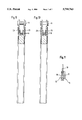
- FIG. 7 is a section through a plate which is cushioned on one side in the vicinity of the outer friction lining, in the unpressurized operating condition;
- FIG. 8 is the same as FIG. 7, but in the pressurized operating condition
- FIG. 9 is the same as FIG. 7, but is cushioned on both sides, in the unpressurized operating condition
- FIG. 10 is the same as FIG. 9, cushioned on both sides, in the pressurized operating condition.
- FIG. 11 illustrates a lock-up clutch with a plate provided on the two sides thereof with friction surfaces of different elasticities.
- FIG. 1 The basic structure of a lock-up clutch of a hydrodynamic torque converter is explained in FIG. 1.
- the lock-up clutch 1 interacts with a converter housing 2, only a portion of which is shown, and which is fastened to the crankshaft of an internal combustion engine and is rotationally driven thereby.
- a turbine wheel 3 Located in the converter housing 2 and at some axial distance from it is a turbine wheel 3 which is fastened to a turbine hub 5, which is fitted non-rotationally to an output shaft 6.
- the converter housing 2 includes a pump wheel 60 that is mounted inside of the converter housing 2 and rotates therewith.
- a pin member 32 can be provided for positioning the torque converter housing 2.
- the lock-up clutch 1 has a piston 7 which is non-rotationally connected to the converter housing 2 in the radially inner area by means of a spring 30 with a housing 31, and can be displaced in the axial direction to a limited extent out of an idle position.
- the piston 7 is provided with a flat area 8a which lies on the radial outside, and which can be brought into contact with a friction zone 11 fastened to a plate 10.
- This friction zone 11 consists of two friction linings 17, 18 (shown in more detail, e.g., in FIGS. 2-6) which preferably have different axial dimensions (or thicknesses), whereby the friction lining 17 with the greater axial dimension is preferably located on the radial outside.
- the plate 10 is fastened by means of a clamp 12 to the turbine wheel 3, but is connected so that it can move axially with respect to the turbine wheel 3.
- the plate 10 On its side facing away from the friction zone 11, the plate 10 has an additional friction zone 13.
- This friction zone 13 consists of two friction linings 15, 16 (seen in more detail, e.g., in FIGS. 2-6) which preferably have different axial dimensions, whereby the friction lining 15 with the greater axial dimension is preferably located on the radial outside.
- This friction zone 13 comes into effective contact with a matching friction surface 14 of the converter housing 2.
- These friction linings 15, 16, 17, 18 located on the plate 10 are preferably provided with channels in the form of grooves 19, as illustrated in FIGS. 4-6.
- the path of the grooves 19 in the friction linings is laid out so that a chamber 25 (shown in FIG. 1), which is defined on one side by the converter housing 2 and on the other side by the piston 7, can be reached through these grooves by the oil (or other hydraulic fluids) which originates from the interior chamber of the converter.
- a boring 27 Radially inside the chamber 25, between the turbine hub 5 and the converter housing 2, there is a boring 27.
- the oil which flows radially inward into the chamber 25 can get into the center of the torque converter, from where it can be pumped out by means of a central boring 26 in the output shaft 6 into a reservoir for oil (e.g., hydraulic fluid).
- the converter housing 2 uses the torque which is generated by the internal combustion engine to drive a pump (e.g., pump wheel 60) which, by means of a hydraulic medium, preferably oil, causes the turbine wheel 3 to revolve.
- a pump e.g., pump wheel 60
- the turbine wheel 3 by means of the turbine hub 5, transmits this rotational motion by means of a gearing (or splined fitting) 29, by means of which the turbine hub 5 is engaged with the output shaft 6, to the output shaft 6, which is connected in a manner not shown with a transmission.
- gearing or splined fitting
- a lock-up clutch 1 which, when the piston 7 is pressurized from the turbine wheel side, causes the piston 7 to be held in an effective connection with the converter housing 2 by means of the friction zones 11 and 13 provided on the plate 10.
- the torque is transmitted directly from the converter housing 2 and from the piston 7 by means of the corresponding friction zones 11 and 13 respectively to the plate 10, and from the plate 10 by means of the clamp 12 to the turbine wheel 3, from where it is transmitted by means of the gearing 29 of the turbine hub 5 to the output shaft 6.
- the hydraulic transmission path is thereby closed by the lock-up clutch 1, and no further slip takes place.
- the side of the piston 7 facing the converter housing 2 is pressurized with hydraulic fluid by means of a corresponding supply line 20, as a result of which the piston 7 is moved away from the converter housing 2 and the plate 10 provided with the friction zones 11 and 13 is thereby depressurized (or unclamped).
- the torque transmission to the friction zones 11 and 13 and via the plate 10 and the clamp 12 to the turbine wheel 3 thereby ends.
- Each friction zone 11, 13 consists of two friction surfaces 15 and 16; 17 and 18, which are disposed radially next to one another.
- a low application pressure is exerted, and only the friction linings 15, 17 with the greatest axial dimension and preferably a higher elasticity are in effective contact with the matching friction surface, as illustrated in FIG. 2.
- the surface pressure increases, whereby the slip and the amount of heat released decrease.
- the axial dimension of the friction linings which are in effective contact can be adjusted as a function of the application pressure by an appropriate choice of the elasticity.
- the reduction of the axial dimension of the friction linings of the friction zones is accompanied by a reduction of the groove cross section, as a result of which the flow of coolant through the friction zones is reduced.
- a groove pattern which continues through into the second friction lining of a friction zone, as illustrated in FIG. 6, can also be employed to achieve a reduction of the coolant flow through this friction zone, as can a change in the direction of the groove, and smaller cross sections of the grooves.
- the greater axial dimension of the friction linings can also be achieved by attaching the friction linings to cushioned (or biased, e.g., spring biased) components.
- the two friction linings 23 shown in FIGS.
- FIG. 7 illustrates a simple construction of a cushioning by means of an annular spring 8, which is in the unpressurized condition.
- the surfaces of the friction linings of a friction zone are on the same level, as shown in FIG. 8. That is, there is no axial distance 24 between the radially disposed friction linings.
- the plate 10 can also be cushioned on both sides (for example by a pair of annular springs 8), as in the embodiment illustrated in FIGS. 9 and 10.
- a safety element 9 To adjust the operating range of the spring 8 and to limit the maximum axial dimension, there is preferably provided a safety element 9.
- the coolant flow can preferably be reduced, which can be achieved by several different means. It is possible that the grooves 19 in the elastic friction linings can be reduced or closed by the application pressure when the axial dimension is reduced. It is also possible that the friction surfaces which come into effective contact at higher pressures can have a smaller number of grooves 19.
- FIG. 4 shows a friction lining of the friction surface 15, 17, which friction lining is located radially outward on the plate 10, and whereby the edge (or periphery) which is directed radially inward is realized in the shape of a polygon 21.
- the friction lining which forms the radially inner friction surface 16, 18 also has such a polygon-shaped edge (or periphery) 21, as shown in FIG. 5, on the radial outside, so that the two friction linings 15, 17 and 16, 18 can be connected positively, this positive or interlocking connection being illustrated by reference numeral 22.
- the two friction linings are connected to one another so that the groove pattern extends over both friction linings 15, 17 and 16, 18.
- the plate 10 illustrated in FIG. 11 has respective friction surfaces 115, 117 on both sides, whereby these friction linings have different elasticities.
- the two friction linings each come in contact with their corresponding matching friction surfaces.
- the groove cross section in the friction lining with the greater elasticity is reduced, whereby the coolant flow can also be controlled by the pressure exerted by the converter.
- frictional engagement zones 11 and 13 including the friction linings 15-18 are disposed on the surfaces of the clampable member or plate 10
- the friction linings could be alternatively disposed on the surfaces of the piston 7 and/or the torque converter housing 2.
- the friction linings need only be positioned within the clampable area located between the piston 7 and the torque converter housing 2, so that one of the friction linings is contacted initially as the piston 7 is displaced toward the torque converter housing 2 and another of the friction linings is contacted upon a further subsequent movement of the piston 7 toward the torque converter housing 2.
- lock-up clutches in torque converters are known wherein the piston is rotationally connected to the turbine wheel and wherein an axial displacement of the piston brings it into contact with the rotationally driven torque converter housing. Friction linings disposed on either or both of the piston and the torque converter housing then act to transfer the torque from the torque converter housing, through the friction linings and the piston to the turbine wheel.
- the present invention can be employed in such lock-up clutches for torque converters of this type wherein the friction linings of the invention need only be positioned between the piston and the torque converter housing.
- One feature of the invention resides broadly in the lock-up clutch of a hydrodynamic torque converter which comprises at least one piston which can be displaced in the axial direction and can be connected to the converter housing by means of at least one friction zone, which piston defines, by means of the side which faces the converter housing, a chamber in which, when the lock-up clutch is active, the pressure is lower than in the converter circuit, and which, in the vicinity of a friction zone, has at least one channel for the flow of hydraulic fluid from the converter circuit, whereby the quantitative flow of hydraulic fluid is a function of the pressure exerted by the converter, characterized by the fact that the lock-up clutch 1 comprises at least one friction zone 11, 13 which has at least one friction lining 15-18, whereby the lock-up clutch has a total of at least two friction linings of differential axial dimensions (or heights) which, in the event of different pressures acting in the converter, come into at least partial effective connection with the matching friction surface 14.
- each friction zone 11, 13 consists of a plurality of friction linings 15, 16; 17, 18 which are located radially next to one another.
- Yet another feature of the invention resides broadly in the lock-up clutch characterized by the fact that one of the friction zones 11, 13 consists of at least two friction linings 15-18 which are located axially one behind the other.
- Still another feature of the invention resides broadly in the hydrodynamic torque converter characterized by the fact that the friction linings 15 and 16; 17 and 18 can be connected to one another.
- a further feature of the invention resides broadly in the hydrodynamic torque converter characterized by the fact that the friction linings 15 and 16; 17 and 18 provided in one friction zone 11, 13 have different elasticities.
- Another feature of the invention resides broadly in the hydrodynamic torque converter characterized by the fact that the friction lining 15, 17 which first enters into an effective connection with the matching friction surface 14 as a result of the pressurization of the piston has a high elasticity.
- Yet another feature of the invention resides broadly in the hydrodynamic torque converter characterized by the fact that the friction lining 15-18, when pressurized by the application pressure, can be elastically deformed so that it becomes possible to control the coolant flow of the hydraulic fluid.
- Still another feature of the invention resides broadly in the hydrodynamic torque converter characterized by the fact that the number of friction linings which are effectively connected to the matching friction surface can be increased by increasing the application pressure.
- a further feature of the invention resides broadly in the hydrodynamic torque converter characterized by the fact that the friction linings 15 and 16; 17 and 18 of one friction zone 13, 11 can be connected positively.
- Another feature of the invention resides broadly in the hydrodynamic torque converter characterized by the fact that at least one of the friction linings 15, 17 is located on a cushioned or (spring-mounted) component.
- Yet another feature of the invention resides broadly in the hydrodynamic torque converter characterized by the fact that the surfaces of the friction linings run parallel to the corresponding matching friction surfaces.
- Still another feature of the invention resides broadly in the hydrodynamic torque converter characterized by the fact that the path of the channels 19 of one friction lining 15 and 16; 17 and 18 continues into the neighboring friction lining of a friction zone.
- a further feature of the invention resides broadly in the hydrodynamic torque converter characterized by the fact that the positively connected friction linings 15 and 16; 17 and 18 can be connected by means of a polygon.
- Another feature of the invention resides broadly in the hydrodynamic torque converter characterized by the fact that the cushioned component is cushioned by means of an annular spring 8.
- Yet another feature of the invention resides broadly in the hydrodynamic torque converter characterized by the fact that the maximum dimension of the cushioned component is limited by a safety element 9.
- Still another feature of the invention resides broadly in the hydrodynamic torque converter characterized by the fact that the friction zone comprises at least two friction linings located radially next to one another, whereby preferably the friction lining which is located on the radial outside is cushioned.
- a further feature of the invention resides broadly in the lock-up clutch characterized by the fact that the lock-up clutch 1 has at least two friction linings 115, 117 which have different elasticities.
- Another feature of the invention resides broadly in the lock-up clutch characterized by the fact that when there is a sufficiently high pressure exerted by the converter, the friction linings 115, 117 enter into an effective connection, each with the respective matching friction surface corresponding to the friction lining, almost simultaneously.
Landscapes
- Engineering & Computer Science (AREA)
- General Engineering & Computer Science (AREA)
- Mechanical Engineering (AREA)
- Mechanical Operated Clutches (AREA)
- Hydraulic Clutches, Magnetic Clutches, Fluid Clutches, And Fluid Joints (AREA)
- Control Of Fluid Gearings (AREA)
Applications Claiming Priority (4)
| Application Number | Priority Date | Filing Date | Title |
|---|---|---|---|
| DE19536954 | 1995-10-04 | ||
| DE19536954.8 | 1995-10-04 | ||
| DE19622593.0 | 1996-06-05 | ||
| DE19622593A DE19622593C2 (de) | 1995-10-04 | 1996-06-05 | Überbrückungskupplung eines hydrodynamischen Drehmomentwandlers |
Publications (1)
| Publication Number | Publication Date |
|---|---|
| US5799763A true US5799763A (en) | 1998-09-01 |
Family
ID=26019233
Family Applications (1)
| Application Number | Title | Priority Date | Filing Date |
|---|---|---|---|
| US08/725,361 Expired - Fee Related US5799763A (en) | 1995-10-04 | 1996-10-03 | Lock-up clutch of a hydrodynamic torque converter |
Country Status (4)
| Country | Link |
|---|---|
| US (1) | US5799763A (fr) |
| ES (1) | ES2139487B1 (fr) |
| FR (1) | FR2739671B1 (fr) |
| GB (1) | GB2305984B (fr) |
Cited By (30)
| Publication number | Priority date | Publication date | Assignee | Title |
|---|---|---|---|---|
| US5921366A (en) * | 1994-01-21 | 1999-07-13 | Luk Getriebe-Systeme Gmbh | Friction element for use in clutches |
| US5975260A (en) * | 1996-08-23 | 1999-11-02 | Luk Getriebe-Systeme Gmbh | Hydrokinetic torque convertor with bypass clutch having grooved friction lining |
| US6000510A (en) * | 1996-10-23 | 1999-12-14 | Borg-Warner Automotive, Inc. | Functionally enhanced hydrokinetic device having clutch assembly operable at low engine speeds |
| US6006877A (en) * | 1996-02-01 | 1999-12-28 | Zf Friedrichshafen Ag | Hydraulic clutch for high friction applications |
| US6006878A (en) * | 1999-02-12 | 1999-12-28 | Ford Global Technologies, Inc. | Torque converter bypass clutch having elastically flexible piston |
| US20030000790A1 (en) * | 2001-06-27 | 2003-01-02 | Zf Sachs Ag | Lock-up clutch for a hydrodynamic torque converter |
| US20040026202A1 (en) * | 2002-05-02 | 2004-02-12 | Cannon Clint D. | Torque converter |
| US20040178037A1 (en) * | 2003-03-11 | 2004-09-16 | Jorg Sudau | Bridging clutch for a hydrodynamic torque converter |
| US20040251109A1 (en) * | 2003-06-11 | 2004-12-16 | Euroflamm Select Inc. | System and method for improving cooling in a friction facing environment |
| US20050072649A1 (en) * | 2003-10-02 | 2005-04-07 | Euroflamm Select Inc. | Friction facing material for use in a friction environment |
| US20050071979A1 (en) * | 2003-10-02 | 2005-04-07 | Euroflamm Select Inc. | Friction facing method for use in a friction environment |
| US20050155831A1 (en) * | 2004-01-19 | 2005-07-21 | Fuji Jukogyo Kabushiki Kaisha | Torque converter |
| US20050211521A1 (en) * | 2004-03-23 | 2005-09-29 | Exedy Corporation | Lockup device for hydraulic torque transmission device |
| US20050284721A1 (en) * | 2004-06-25 | 2005-12-29 | Arcot Murali K S | Clutch cooling grooves for uniform plate temperature in friction launch |
| US20060102443A1 (en) * | 2004-10-06 | 2006-05-18 | Nsk-Warner K.K. | Friction plate for wet-type multiplate clutch |
| US7080720B1 (en) | 2005-02-24 | 2006-07-25 | Blumental Automatic, Inc. | Torque converter |
| US20060180423A1 (en) * | 2005-02-15 | 2006-08-17 | Thomas Kos | Torque converter with a lock-up clutch assembly having a floating friction disk |
| US20060236523A1 (en) * | 2003-10-02 | 2006-10-26 | Sulzer Euroflamm Us Inc | Friction facing method for use in a friction environment |
| US20070119674A1 (en) * | 2005-11-25 | 2007-05-31 | Nsk-Warner K.K. | Lockup clutch |
| US20070119675A1 (en) * | 2005-11-25 | 2007-05-31 | Nsk-Warner K.K. | Lockup clutch |
| WO2007098872A1 (fr) * | 2006-02-24 | 2007-09-07 | Daimler Ag | Convertisseur de couple hydrodynamique muni d'un accouplement à pontage |
| US20070270069A1 (en) * | 2006-05-18 | 2007-11-22 | Sulzer Euroflamm Us Inc. | Friction material and system and method for making the friction material |
| US20080087518A1 (en) * | 2006-10-16 | 2008-04-17 | Gregory Mordukhovich | Clutch for a transmission |
| US20080099291A1 (en) * | 2006-10-31 | 2008-05-01 | Cannon Clint D | Torque converter with fluid and viscous couplings |
| US7503441B2 (en) | 2003-05-02 | 2009-03-17 | Cannon Clint D | Torque converter |
| US20100006388A1 (en) * | 2006-09-26 | 2010-01-14 | Borgwarner Inc. | Friction part for a frictionally acting device, and frictionally acting device having a friction part of said type |
| US20150047193A1 (en) * | 2013-08-13 | 2015-02-19 | Schaeffler Technologies Gmbh & Co. Kg | Pre-stressed torque converter shell |
| US9004253B2 (en) | 2013-06-26 | 2015-04-14 | Ford Global Technologies, Llc | Control of fluid flow in an automatic transmission |
| JP2018536809A (ja) * | 2015-11-09 | 2018-12-13 | ツェットエフ、フリードリッヒスハーフェン、アクチエンゲゼルシャフトZf Friedrichshafen Ag | 摩擦結合型シフト要素用のプレート |
| US10260611B2 (en) * | 2017-03-31 | 2019-04-16 | Valeo Embrayages | Hydrokinetic torque coupling device having turbine-piston lockup clutch, and related methods |
Citations (14)
| Publication number | Priority date | Publication date | Assignee | Title |
|---|---|---|---|---|
| US2058655A (en) * | 1934-10-12 | 1936-10-27 | Borg Warner | Friction clutch |
| US2135126A (en) * | 1934-10-24 | 1938-11-01 | Russell Mfg Co | Friction clutch |
| GB955066A (en) * | 1961-12-12 | 1964-04-15 | Ferodo Sa | Improvements in and relating to clutches |
| US3907073A (en) * | 1972-10-12 | 1975-09-23 | Girling Ltd | Multi-plate disc brakes for vehicles |
| US4469206A (en) * | 1981-02-21 | 1984-09-04 | Aisin Warner Kabushiki Kaisha | Hydraulically-operated frictional engagement device |
| US5056631A (en) * | 1989-07-10 | 1991-10-15 | Ford Motor Company | Slipping bypass clutch construction for a hydrokinetic torque converter |
| US5184704A (en) * | 1991-08-12 | 1993-02-09 | Hays Bill J | Clutch design and manufacture |
| US5383540A (en) * | 1993-10-04 | 1995-01-24 | Ford Motor Company | Torque converter bypass clutch piston-pump drive for an automatic transmission |
| DE4425912A1 (de) * | 1993-07-30 | 1995-02-02 | Luk Getriebe Systeme Gmbh | Hydrodynamischer Strömungswandler |
| GB2285851A (en) * | 1994-01-21 | 1995-07-26 | Luk Getriebe Systeme Gmbh | Bridging clutch friction ring |
| DE4407727A1 (de) * | 1994-03-08 | 1995-09-14 | Zahnradfabrik Friedrichshafen | Drehmomentwandler und Wandlerüberbrückungskupplung |
| US5566802A (en) * | 1995-07-17 | 1996-10-22 | Borg-Warner Automotive, Inc. | Continuous slip hydrokinetic torque converter clutch interface with curcuitous groove for cooling and wetting clutch interface zone |
| US5667043A (en) * | 1994-05-09 | 1997-09-16 | Fichtel & Sachs Ag | Hydrodynamic torque converter with lockup clutch |
| US5669474A (en) * | 1994-09-14 | 1997-09-23 | Fichtel & Sachs Ag | Hydrodynamic torque converter with lock-up clutch |
Family Cites Families (6)
| Publication number | Priority date | Publication date | Assignee | Title |
|---|---|---|---|---|
| JPS58184321A (ja) * | 1982-04-23 | 1983-10-27 | Toyota Motor Corp | クリ−プ装置付きクラツチ |
| EP0267027B1 (fr) * | 1986-11-04 | 1991-05-29 | Daikin-R/M Co. Ltd. | Disque de friction à segments |
| US4934495A (en) * | 1989-03-29 | 1990-06-19 | Rockwell International Corporation | Lock-up clutch for four element torque converter |
| DE69314550T2 (de) * | 1992-07-03 | 1998-03-26 | Toyota Motor Co Ltd | Hydraulische Drehmoment-Übertragungseinheit mit Überbrückungskupplung |
| JP3214208B2 (ja) * | 1993-04-13 | 2001-10-02 | トヨタ自動車株式会社 | 湿式クラッチ |
| FR2709165B1 (fr) * | 1993-08-16 | 1995-10-13 | Valeo | Transmission à accouplement hydrocinétique débrayable, notamment pour véhicules automobiles. |
-
1996
- 1996-09-23 ES ES009602004A patent/ES2139487B1/es not_active Expired - Fee Related
- 1996-10-03 US US08/725,361 patent/US5799763A/en not_active Expired - Fee Related
- 1996-10-04 GB GB9620914A patent/GB2305984B/en not_active Expired - Fee Related
- 1996-10-04 FR FR9612130A patent/FR2739671B1/fr not_active Expired - Fee Related
Patent Citations (15)
| Publication number | Priority date | Publication date | Assignee | Title |
|---|---|---|---|---|
| US2058655A (en) * | 1934-10-12 | 1936-10-27 | Borg Warner | Friction clutch |
| US2135126A (en) * | 1934-10-24 | 1938-11-01 | Russell Mfg Co | Friction clutch |
| GB955066A (en) * | 1961-12-12 | 1964-04-15 | Ferodo Sa | Improvements in and relating to clutches |
| US3907073A (en) * | 1972-10-12 | 1975-09-23 | Girling Ltd | Multi-plate disc brakes for vehicles |
| US4469206A (en) * | 1981-02-21 | 1984-09-04 | Aisin Warner Kabushiki Kaisha | Hydraulically-operated frictional engagement device |
| US5056631A (en) * | 1989-07-10 | 1991-10-15 | Ford Motor Company | Slipping bypass clutch construction for a hydrokinetic torque converter |
| US5184704A (en) * | 1991-08-12 | 1993-02-09 | Hays Bill J | Clutch design and manufacture |
| DE4425912A1 (de) * | 1993-07-30 | 1995-02-02 | Luk Getriebe Systeme Gmbh | Hydrodynamischer Strömungswandler |
| US5501309A (en) * | 1993-07-30 | 1996-03-26 | Luk Getriebe-Systeme Gmbh | Hydrokinetic torque converter with lockup clutch |
| US5383540A (en) * | 1993-10-04 | 1995-01-24 | Ford Motor Company | Torque converter bypass clutch piston-pump drive for an automatic transmission |
| GB2285851A (en) * | 1994-01-21 | 1995-07-26 | Luk Getriebe Systeme Gmbh | Bridging clutch friction ring |
| DE4407727A1 (de) * | 1994-03-08 | 1995-09-14 | Zahnradfabrik Friedrichshafen | Drehmomentwandler und Wandlerüberbrückungskupplung |
| US5667043A (en) * | 1994-05-09 | 1997-09-16 | Fichtel & Sachs Ag | Hydrodynamic torque converter with lockup clutch |
| US5669474A (en) * | 1994-09-14 | 1997-09-23 | Fichtel & Sachs Ag | Hydrodynamic torque converter with lock-up clutch |
| US5566802A (en) * | 1995-07-17 | 1996-10-22 | Borg-Warner Automotive, Inc. | Continuous slip hydrokinetic torque converter clutch interface with curcuitous groove for cooling and wetting clutch interface zone |
Cited By (46)
| Publication number | Priority date | Publication date | Assignee | Title |
|---|---|---|---|---|
| US5921366A (en) * | 1994-01-21 | 1999-07-13 | Luk Getriebe-Systeme Gmbh | Friction element for use in clutches |
| US6006877A (en) * | 1996-02-01 | 1999-12-28 | Zf Friedrichshafen Ag | Hydraulic clutch for high friction applications |
| US5975260A (en) * | 1996-08-23 | 1999-11-02 | Luk Getriebe-Systeme Gmbh | Hydrokinetic torque convertor with bypass clutch having grooved friction lining |
| US6000510A (en) * | 1996-10-23 | 1999-12-14 | Borg-Warner Automotive, Inc. | Functionally enhanced hydrokinetic device having clutch assembly operable at low engine speeds |
| US6006878A (en) * | 1999-02-12 | 1999-12-28 | Ford Global Technologies, Inc. | Torque converter bypass clutch having elastically flexible piston |
| US6742637B2 (en) * | 2001-06-27 | 2004-06-01 | Zf Sachs Ag | Lock-up clutch for a hydrodynamic torque converter |
| US20030000790A1 (en) * | 2001-06-27 | 2003-01-02 | Zf Sachs Ag | Lock-up clutch for a hydrodynamic torque converter |
| US20040026202A1 (en) * | 2002-05-02 | 2004-02-12 | Cannon Clint D. | Torque converter |
| US6871733B2 (en) * | 2002-05-02 | 2005-03-29 | Automotive Transmission Specialists, Inc. | Torque converter |
| US20040178037A1 (en) * | 2003-03-11 | 2004-09-16 | Jorg Sudau | Bridging clutch for a hydrodynamic torque converter |
| US7011196B2 (en) * | 2003-03-11 | 2006-03-14 | Zf Sachs Ag | Bridging clutch for a hydrodynamic torque converter |
| US7503441B2 (en) | 2003-05-02 | 2009-03-17 | Cannon Clint D | Torque converter |
| US20040251109A1 (en) * | 2003-06-11 | 2004-12-16 | Euroflamm Select Inc. | System and method for improving cooling in a friction facing environment |
| US7014024B2 (en) | 2003-06-11 | 2006-03-21 | Sulzer Euroflamm Us Inc. | System and method for improving cooling in a friction facing environment |
| US20060236523A1 (en) * | 2003-10-02 | 2006-10-26 | Sulzer Euroflamm Us Inc | Friction facing method for use in a friction environment |
| US7168544B2 (en) | 2003-10-02 | 2007-01-30 | Sulzer Euroflamm Us Inc. | Friction facing material for use in a friction environment |
| US20050072649A1 (en) * | 2003-10-02 | 2005-04-07 | Euroflamm Select Inc. | Friction facing material for use in a friction environment |
| US20050071979A1 (en) * | 2003-10-02 | 2005-04-07 | Euroflamm Select Inc. | Friction facing method for use in a friction environment |
| US7069636B2 (en) | 2003-10-02 | 2006-07-04 | Euroflamm Select Inc. | Friction facing method for use in a friction environment |
| US20050155831A1 (en) * | 2004-01-19 | 2005-07-21 | Fuji Jukogyo Kabushiki Kaisha | Torque converter |
| US7234577B2 (en) * | 2004-01-19 | 2007-06-26 | Fuji Jukogyo Kabushiki Kaisha | Torque converter |
| US7222706B2 (en) * | 2004-03-23 | 2007-05-29 | Exedy Corporation | Lockup device for hydraulic torque transmission device |
| US20050211521A1 (en) * | 2004-03-23 | 2005-09-29 | Exedy Corporation | Lockup device for hydraulic torque transmission device |
| US7448483B2 (en) * | 2004-06-25 | 2008-11-11 | General Motors Corporation | Clutch cooling grooves for uniform plate temperature in friction launch |
| US20050284721A1 (en) * | 2004-06-25 | 2005-12-29 | Arcot Murali K S | Clutch cooling grooves for uniform plate temperature in friction launch |
| US20060102443A1 (en) * | 2004-10-06 | 2006-05-18 | Nsk-Warner K.K. | Friction plate for wet-type multiplate clutch |
| US7392891B2 (en) * | 2004-10-06 | 2008-07-01 | Nsk-Warner K.K. | Friction plate for wet-type multiplate clutch |
| US7357233B2 (en) | 2005-02-15 | 2008-04-15 | Borgwarner Inc. | Torque converter with a lock-up clutch assembly having a floating friction disk |
| US20060180423A1 (en) * | 2005-02-15 | 2006-08-17 | Thomas Kos | Torque converter with a lock-up clutch assembly having a floating friction disk |
| US7080720B1 (en) | 2005-02-24 | 2006-07-25 | Blumental Automatic, Inc. | Torque converter |
| US20070119674A1 (en) * | 2005-11-25 | 2007-05-31 | Nsk-Warner K.K. | Lockup clutch |
| US7757827B2 (en) * | 2005-11-25 | 2010-07-20 | Nsk-Warner K.K. | Lockup clutch |
| US20070119675A1 (en) * | 2005-11-25 | 2007-05-31 | Nsk-Warner K.K. | Lockup clutch |
| WO2007098872A1 (fr) * | 2006-02-24 | 2007-09-07 | Daimler Ag | Convertisseur de couple hydrodynamique muni d'un accouplement à pontage |
| US20070270069A1 (en) * | 2006-05-18 | 2007-11-22 | Sulzer Euroflamm Us Inc. | Friction material and system and method for making the friction material |
| US20100006388A1 (en) * | 2006-09-26 | 2010-01-14 | Borgwarner Inc. | Friction part for a frictionally acting device, and frictionally acting device having a friction part of said type |
| US8424664B2 (en) * | 2006-09-26 | 2013-04-23 | Borgwarner, Inc. | Friction part for a frictionally acting device |
| US20080087518A1 (en) * | 2006-10-16 | 2008-04-17 | Gregory Mordukhovich | Clutch for a transmission |
| US7886885B2 (en) * | 2006-10-16 | 2011-02-15 | GM Global Technology Operations LLC | Clutch for a transmission |
| US20080099291A1 (en) * | 2006-10-31 | 2008-05-01 | Cannon Clint D | Torque converter with fluid and viscous couplings |
| US7717243B2 (en) | 2006-10-31 | 2010-05-18 | Cannon Clint D | Torque converter with fluid and viscous couplings |
| US9004253B2 (en) | 2013-06-26 | 2015-04-14 | Ford Global Technologies, Llc | Control of fluid flow in an automatic transmission |
| US20150047193A1 (en) * | 2013-08-13 | 2015-02-19 | Schaeffler Technologies Gmbh & Co. Kg | Pre-stressed torque converter shell |
| US9523419B2 (en) * | 2013-08-13 | 2016-12-20 | Schaeffler Technologies AG & Co. KG | Pre-stressed torque converter shell |
| JP2018536809A (ja) * | 2015-11-09 | 2018-12-13 | ツェットエフ、フリードリッヒスハーフェン、アクチエンゲゼルシャフトZf Friedrichshafen Ag | 摩擦結合型シフト要素用のプレート |
| US10260611B2 (en) * | 2017-03-31 | 2019-04-16 | Valeo Embrayages | Hydrokinetic torque coupling device having turbine-piston lockup clutch, and related methods |
Also Published As
| Publication number | Publication date |
|---|---|
| FR2739671B1 (fr) | 1999-08-06 |
| ES2139487B1 (es) | 2000-09-16 |
| GB2305984B (en) | 1999-09-08 |
| GB9620914D0 (en) | 1996-11-27 |
| GB2305984A (en) | 1997-04-23 |
| ES2139487A1 (es) | 2000-02-01 |
| FR2739671A1 (fr) | 1997-04-11 |
Similar Documents
| Publication | Publication Date | Title |
|---|---|---|
| US5799763A (en) | Lock-up clutch of a hydrodynamic torque converter | |
| US4177885A (en) | Torque converter and lock-up clutch | |
| US6622839B2 (en) | Multiple clutch arrangement | |
| US5495927A (en) | Controlled cooling apparatus for torque transfer devices | |
| US5887690A (en) | Clutch arrangement | |
| EP1460313B1 (fr) | Convertisseur de couple avec embrayage de pontage | |
| US5738198A (en) | Friction element for use in clutches | |
| US5240095A (en) | Hydraulic frictional device | |
| US20080308374A1 (en) | Hydrodynamic torque converter having a bypass clutch | |
| KR19980033105A (ko) | 낮은 엔진 속도에서 동작할 수 있는 클러치 장치를 갖는 기능적으로 개선된 유체 운동 장치 | |
| US20070039796A1 (en) | Clutch device | |
| GB2328254A (en) | Hydrodynamic torque converter | |
| US7731005B2 (en) | Lock-up clutch mechanism for torque converter | |
| JP3623547B2 (ja) | ロックアップ機構付きトルクコンバータ | |
| KR101055839B1 (ko) | 자동차의 토크 컨버터 | |
| US4478323A (en) | Hydrodynamic clutch with torsional vibration damping | |
| JPS61157834A (ja) | 始動クラツチ | |
| US4643289A (en) | Wet clutch disc | |
| JP4831575B2 (ja) | 発進クラッチ | |
| US4626226A (en) | Torque fluctuation damper | |
| KR101437152B1 (ko) | 클러치 | |
| US5794751A (en) | Piston for torque transmitting systems | |
| KR20110094918A (ko) | 마찰요소 | |
| KR101056852B1 (ko) | 차량용 토크 컨버터 | |
| US8500580B2 (en) | Torque sensor for a belt-driven conical-pulley transmission |
Legal Events
| Date | Code | Title | Description |
|---|---|---|---|
| AS | Assignment |
Owner name: FICHTEL & SACHS AG, GERMANY Free format text: ASSIGNMENT OF ASSIGNORS INTEREST;ASSIGNOR:DEHRMANN, UWE;REEL/FRAME:008368/0639 Effective date: 19960917 Owner name: FICHTEL & SACHS AG, GERMANY Free format text: ASSIGNMENT OF ASSIGNORS INTEREST;ASSIGNOR:DEHRMANN, UWE;REEL/FRAME:008389/0168 Effective date: 19960917 |
|
| FEPP | Fee payment procedure |
Free format text: PAYOR NUMBER ASSIGNED (ORIGINAL EVENT CODE: ASPN); ENTITY STATUS OF PATENT OWNER: LARGE ENTITY |
|
| CC | Certificate of correction | ||
| FPAY | Fee payment |
Year of fee payment: 4 |
|
| REMI | Maintenance fee reminder mailed | ||
| LAPS | Lapse for failure to pay maintenance fees | ||
| STCH | Information on status: patent discontinuation |
Free format text: PATENT EXPIRED DUE TO NONPAYMENT OF MAINTENANCE FEES UNDER 37 CFR 1.362 |
|
| FP | Lapsed due to failure to pay maintenance fee |
Effective date: 20060901 |