US577149A - -bobbins - Google Patents
-bobbins Download PDFInfo
- Publication number
- US577149A US577149A US577149DA US577149A US 577149 A US577149 A US 577149A US 577149D A US577149D A US 577149DA US 577149 A US577149 A US 577149A
- Authority
- US
- United States
- Prior art keywords
- pistol
- rod
- pedestal
- coin
- lever
- Prior art date
- Legal status (The legal status is an assumption and is not a legal conclusion. Google has not performed a legal analysis and makes no representation as to the accuracy of the status listed.)
- Expired - Lifetime
Links
Images


Classifications
-
- G—PHYSICS
- G07—CHECKING-DEVICES
- G07F—COIN-FREED OR LIKE APPARATUS
- G07F5/00—Coin-actuated mechanisms; Interlocks
- G07F5/02—Coin-actuated mechanisms; Interlocks actuated mechanically by coins, e.g. by a single coin
Definitions
- a TTORNE/J' 1o lowing is a specification, reference being bad 20 and arrangement of parts, as hereinafter de- .'-ating machine constructed according to the Q 35 tudinal section of the box and lower part of 45 tional view of the part lying between the lines UNITED Y STATES PATENT' OFFI E,
- This-invention relates to that class of coinoperated machines in which a personintroducing a coin is permitted to fire at a target and in which the accuracy of the shot is re- ,corded by a suitable register; and the invcn tion comprises various details of construction scribed.
- Figure 1 is a side elevation of'a coin-oper-' present invention.
- Fig. 2 is a front elevation thereof
- Fig. 3 is a plan thereof.
- Fig. 4 is a vertical longitudinal section of a part thereof with the supporting-frame removed.
- Fig. 5 is a sectional plan thereof.
- Fig. 6 is a front elevation thereof with the door removed.
- Fig. 7 is a rear elevation thereof with the. case or cover removed.
- Fig. 8 is a vertical longithe pedestal.
- Fig. Sl is avertical section taken on the line 2 2 of Fig. 8.
- Fig. 10. is an elevation of, the parts represented at Fig. Shutshowing them in a diiferent position.
- Fig. 11 is a side elevation of'a coin-oper-' present invention.
- Fig. 2 is a front elevation thereof
- Fig. 3 is a plan thereof.
- Fig. 4 is a vertical longitudinal section of a part thereof with
- Fig. 12 is aplan thereof. Fig.
- FIG. 13 is a vertical longitudinal section of a slightly-modified form of pistol, and Fig. 14
- Fig. 15 is a vertical secn and w of Fig. 1.
- Fig. 16 is a vertical sec- 1 tiona'l View of the part lying between the lines w and y of Fig. 1.
- Figs. 4 to 7 are drawn to an'increased scale with respect to Figs l toil, and.
- Figs; 8' roll a, supported upon the topof t-hecase a, with capability of partial revolution limited by a notch 0 in the disk '0.
- a represents the case of the machine, which is mounted upon a suitable'frame or stand a in order to bring it to a convenient height.
- dummy pistol h furnished with a hammer b and trigger b and toward the rear of the case A a and in the background is arranged avertical wall a*, which carries target 07*" and a regiSter, hereinafter more .fully referred to.
- the pedestal b of the pistol passes through the topof the case a to the interior thereof and is mounted with capability .ofmovement in several directions in the following manner:
- the lower end of the pedestal]; within the case a of the apparatus has fixed therewith a 7: circular box 11*, serving to contain certain mechanism, hereinafter more fully referred to, and the boil) is:axially fixed with studs or trunniou's 12 mounted in bearings formed in lugs c, fixed with an apertured disk or ring stud o fixed with the case, which engagesa/
- the pedestal b is capable of being moved on the axis 12 .to regulate, the elevation of the pistol b, while the pedestal b t0- gethcr with the disk-orring c, is capable of rotary motion in orderto vary the lateral hori-.
- a long guidej-tube bi within which is mounted a projectile rod or needle b the rear end of; which passes into the box b of the pedestal b and the front end ofv which is adapted to be more or less projected beyond the end of the guide-tube b at the times desired, alight spring b* returning the projectile rod or needle I) to its normal position.
- the needle or rod 1' is by the arrangement of parts hereinhefore described caused to accu rately follow the direction given tothe pistol b by a person taking .aim at the visible target a", while in a suitable position oppo Near to; the front 1 of the case a is mounted upon a pedestal b fa w 7 1 dle target 60* in the manner hereinafter dcchine the operator has three shots at the tar-' get.
- the lock of the pistol consists of a dummy hammer b, mounted upon an axis-of motion H below which it is notched at'b to engage asear or projection 11 project-in g from and actuated by the trigger W, as shown more particularly by the dotted lines in Fig.
- the lower end of the piston-rod (Z passes beyond the piston (l and is formed with an eye (1 which engages and loosely connectswith the horizontal arm (1 of a bell-crank lever mounted upon an axis of motion (1 the lower or vertical arm (1 of which lever im- 'pmges upon the rear end of the projectile rod'or needleb, so that upon 'the firing of the pistol by withdrawing the sear 11 from the notch b**'0t the hammer b the coiled spring (1 will, through the lower arm (1 of i the bell-crank lever, give a sudden impulse to the projectile rod or needle b, and, assuming that the aim of the operator is correct,
- the face of the sliding block (1 is formed with an open-sided slot, recess, or guideway 61 therein, extending vertically through the ratchet-teeth (Z within which is mounted with capability of vertical and lateral movement a releasing-bar 01 indirectly connected, as hereinafter described, with the handle or lever, which is actuated to obtain the use of'the machine by a person inserting a coin therein, and this releasing-bar (Z is formed with two inclined cam slots d, through which pass pins (Z fixed with the sliding block (1 the direction of the inclination of the slots (l being such that upon the releasing-bar (I being drawn downward it will advance slightly beyond the face of the ratchet-teeth (1 thus disengaging the clawker d and detent d therefrom, as represented by the dotted lines in Fig.
- a money-slot (0 of the usual character is provided in a hood a arranged, preferably, on the top of thema chine near to the pedestal b of the pistol, and from the coin-slot a *-is arranged a chute a, which conducts the coin into a drum e, provided with a single pocket e, adapted to receive'the same, and the drum 1; is fixed upon one end of a shaft or axis 0 the other end of which passes through the case a and has fixed thereon a coin-operating lever or handle 9*,
- the lever f in its movement engages and raises the outer end of a lever f arranged at;right angles to the lever fand which is mounted upon an axis of motion f and theinner end of which lever f embraces the lower end of the releasing-bar d and acts upon a nut d* at the lower i end thereof to depress the same, and thus restore the mechanism of the pistol to its normal or initial position and permlt it to be f carried cocked and fired, while in the further rotationof the drum e the coin a: is discharged into aswitch-bar g, mounted upon an axis of motion 9* and counterbalanced byaweight g,where'the coin remains for the time being:
- the shaft e of the drum has fixed thereon a square 6 (shown by the dotted lines in Fig. at and full lines in Figs. and 6,) against which presses an arm 1', mount- -ed'upon an axis of motion 1*, and held up to its work with a spring-pressure by aspring '11".
- the invisible target j upon which the projectile rod or needle 1) strikes, is composed of three longitudinally-movable parts, namely, a bullseye j, a surrounding ring or sleeve j, representing an inner, and a still outer ring or sleeve 7' representing an outer.
- each of these parts j j j which is held in its normal position by a spring 10 is capable of independent longitudinalmovement, and has connected therewith a horizontal rod or bar j the rods j of the innerand outer sections of the target being connected to-their respective sleeves j 7' through arms or offsets j"* 3 the rods being guided in bearings formed in a bar or girder 11*;
- a frame j carrying aratchet-tooth or detent j, such teeth being kept up to their work by springs 70, carried by a bar 70*, and in con nection with each ratchet-tooth or detent 7' 7 and at the visible target end of the apparahrs is provided a vertically-mo ⁇ :able bar 70, each bark being formed with three separate ratchet-teeth, forming four steps 10* k is, adapted to engage a corresponding detenttooth of one of the sections j j
- Each of these vertical bars 70 carries at its upper end an indicating slide or shutter 70, which moves vertically behind an aperture a*?, of, or or in the'vertical part (1* of the case, where appears the visible target, the aperture 04* corresponding with the bulls-eye j of the invisible target, the aperture of correspondingwith the inner j and the aperture a** corresponding with the'out-er 3' thereof.
- Each of theslides 7c is numbered with three sets of numerals, each. numeral correspond ing with one of the ratchet-teeth k k? k of the sliding bar It, while the three slides 70 correspond withthe three sectionsjy" 7' of the invisible target, that is to say, the central slide appearing at the aperture af relates to the bulls-eye, one ofthe outer slides, that outer slides relates to the outer section of the invisible target.
- the other slides 10 relating to the inner and outer parts of the invisible target are operated in a similar way to that hereinbefore described, so that the record made by the operator or marksman is altogether dependent upon the skill with which he aims'the pistol b at the visible target 00* and would in most cases be made up of combinations of numbers displayed by the slides 10 at the several apertures (1* a* of.
- the sliding bar 70 corresponding with the aperture a 'and with the bulls-eye j of ,the invisible target, upon g from the switch-bar g, raising the same until the counterweight g assumes the dotted position indicated by two stars in Fig.
- each slide 7.:- is provided with a weight k**, which assists to that end, andin the case of the central slide, it it is important. that the same should have the necessary force in its descentto actuate the lever l.
- a tubular pedestal mounted with capability of universal movement, a pistol rigidly connected with :the upper end of the pedestal, a tubular guide connected with the pedestal, parallel with the pistol, a projectilerod carried by the tubular guide, a simple lock within the pistol consisting of ahammer .controlled by a trigger, a rod within the pedestal at its upper end loosely connected with the hammer, a spring surrounding the rod and acting, to depress it, and a bell-crank lever, one arm of which is acted upon by the lower end of the rod and the other arm of which acts upon the projectile-rod, substantially as herein shown and described.
- the combi nation of a tubular pedestal mounted with capability of universal movement, a pistol rigidly connected with the upper end'of the pedestal, a tubular guide connected with the pedestal, parallel with the pistol, a projectile-rod carried by the tubular guide, a simple look within the pistol consisting of a hammer controlled by a trigger, a rod within the pedestal at its end loosely connected with the hammer, a spring surrounding the rod and acting to depress it, a bell-crank lever one arm of which is acted upon by the lower end of the rod and the other arm of which acts upon the projectile-rod, a vertically-slid- Ice i'ngblock formed with ratchet-teeth upon one face, a clawker carried by that arm of the bell-crank lever connected with the rod and engaging the ratchet -'teeth of the slidingblock and a detent for engaging such teeth and preventing the accidental descent of the sliding block so that each time the pistol is cocked the sliding
- a tubular pedestal mounted with capability of universal movement, a pistol rigidlyconneeted with the upper end of the pedestal, a tub'ularguide connected with'tlie 45 pedestal and parallel with the pistol, a projectile-rod carried by the tubular guide, a simple look within the pistol consisting of a hammer controlled bya trigger, a rod-within the pedestal atfits end loosely connected with the hammer, a spring surrounding the rod and acting to depress it, a bell-crank lever one arm of which is acted upon by the lower end of the rod, and the other arm of which acts upon the projectile-rod, avcrtically-sliding block formed with ratchet-teeth upon one face, a recess in such face, a clawker carried by that arm of the bell-crank lever connected with the rod and engaging the ratchet-teeth of the sliding block and a detent for engaging such teeth and preventing the accidental descent of the sliding block
- a pistol rigidly connected with the upper end of the pedestal, a tubular guide connected.
- tubular guide connected with the pedestal and formed with ratchet-teeth thereon, a detent in ITO connection with each vertical slide for engaging the ratchet-teeth, and connections from each detent to a section of the invisible target, substantially as herein shown and-described and for the purposes stated.
- acoin operatingmachine
- a pedestal mounted with capability of universal movement within certain limits
- a pistol rigidly connected with the upper end of the pedestal
- a tubular guide connected with the pedestal and parallel with the pistol
- a projectile-rod carried by the tubular guide
- a visible target for-the pistol an invisible target for the projectile-rod,consisting of several sections or diameters each capable of independent movement, several apertures in a vertical screen, several vertical slides at the back thereof, and having numerals marked thereon ,several vertically-slidingbars carrying slides and formed with ratchet-teeth thereon, a detent in eonnection with each vertical slide, for engagin D the ratchet-teeth, and connections from each detent to a section of the invisible target, a 1' flexible band attached to each vertical slide and passing over a guide-pulley, the lower. ends of the several flexible connections, being fixed to one arm of.
- a bell-cranklever an'arm or offset fixed with the shaft of the pocketed money-drum and a link flexibly connecting the other arm of the bellcrank lever with sueh'arms or oifsets so that upon the partialfi rotation of the drum the indicating-slides.oi
- the register will be raised to their normal positions, substantially as herein shown and described.
- a pistol rigidly connected with the upper end of the pistol, a tubular guide connected with the pedestal parallel with the pistol, a projectile-rod carried by the guide, means for forcibly projecting the projectilerod.
- a visible target for the pistol an invisible target for the projectile-rod, such target being formed in several sections or diameters each capable of independent movement, several apertures in I -a vertical screen, several vertical slides arranged at the back thereof and having nui lliuiitlfi marked thereon, several vertically sliding bars carrying slides and formedwith ratchet-teeth thereon, a detent in connection with each vertical slide for engaging the tent to a section of the'invisible target, and a money-slot in suitable position, a chute con.- nected therewith, a pocketed (Irwin-arranged beneath the moneyslot, a switch -bar arranged beneath the d rr-nl into which the coin 1 l ratchet-teeth, and connections from each
- projectileg is discharged therefronrya chute for conducttimes, an arm from the axis of the drum'fon cumst-ances, and a lever at one end arranged in the path of the vertical slide of the hullseye aperture, and at the other end adapted. l to tilt the switch-bar so that the coin is discharged into the money-chute retnrnin git to the operator upon a succession'of bulls-eyes being obtained, substantially as hereip shown and described and for the purpose stated] 12.
- a target consisting of several sections or diameters, each capable of independent movement
- avertical screen formed with several apertures
- several slides arranged at the back of the apertures and having figures or signs thereon
- several vertically-sliding bars carrying the slides and provided with ratchet-teeth
- a detent in connection with the teethofeach slide
- c nnections from each i detent to a section. of the target, substanl tially as herein shown and described.
Landscapes
- Physics & Mathematics (AREA)
- General Physics & Mathematics (AREA)
- Toys (AREA)
Description
(No Mo'deLf v SheetS- -Sheet 1.
v. & E. 0. ROBBINS.
v COIN OPERATED MACHINE.
'No. 577,149. Patented Ifeb. 16,1897.
Ffy
- WITNESSES l W C% gfi fflzjwfi er a z gy ATTORNEYS (No Model.)
' 6 Sheets-Sheet '2. V; & E; O. ROBBINS.
GOIN OPERATED MACHINE.
No. 577,149, PatentedFeb" 16, 189-7.
1 In l 4 awi/ll I i I WITNESSES v. & E. Ga-ROBBINS. 00m OPERATED MACHINE,
6 Sheets-Sheet 4.
(No Model.)
No. 577,149. I Patented-Feb. 16, 18,97.-
' mi s/Irons 6 wk 56/ v A TTOBIIE KS' (No ModeL]. a Sheets-Sheet; 5.
v. 85E. 0. ROBBINS. COIN OPERATED MACHINE.
No. 577,149. Patented Feb. 16,1897.
- A TTORNE/J' 1o lowing is a specification, reference being bad 20 and arrangement of parts, as hereinafter de- .'-ating machine constructed according to the Q 35 tudinal section of the box and lower part of 45 tional view of the part lying between the lines UNITED Y STATES PATENT' OFFI E,
VINCENT ROBBINS AND EDGAR CHARLES ROBBINS, OFLQNDON, EN L N '1 COIN-O PERATED- MACHINE.
' srncrmcncrroiv formingpart of Letters Patent No. 577,149, dated February 16, 1897.
' Application filed June 19, 1895 Serial No. 558,260- (No model.) Patented in England May 4,1894, Nor $M.
To aZZ whom it may concern;- 7 Be it known that-we, VINCENT ROBBINS and EDGAR CHARLES ROBBINS, subjects of the Queen of Great Britain, and residents of Stockwell, London, England, have invented certain new and useful Improvements in Coin- Operated Machines, (for which we have obtained a patent in Great Britain, No. 9,082,
hearing date May 4, 1894,) of which the folto the accompanying drawings, forminga part thereof, in which similar letters of reference indicate corresponding parts.
, This-invention relates to that class of coinoperated machines in which a personintroducing a coin is permitted to fire at a target and in which the accuracy of the shot is re- ,corded by a suitable register; and the invcn tion comprises various details of construction scribed.
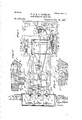
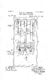
The invention is fully disclosed in the following specification, of which the accompanying drawings form a part, 'in which Figure 1 is a side elevation of'a coin-oper-' present invention. Fig. 2 is a front elevation thereof, and Fig. 3 is a plan thereof. Fig. 4 is a vertical longitudinal section of a part thereof with the supporting-frame removed. Fig. 5 is a sectional plan thereof. Fig. 6 is a front elevation thereof with the door removed. Fig. 7 is a rear elevation thereof with the. case or cover removed. Fig. 8 is a vertical longithe pedestal. Fig. Slis avertical section taken on the line 2 2 of Fig. 8. Fig. 10.is an elevation of, the parts represented at Fig. Shutshowing them in a diiferent position. Fig. 11
is a vertical longitudinal section of a portion of the pistol. Fig. 12 is aplan thereof. Fig.
13 is a vertical longitudinal section of a slightly-modified form of pistol, and Fig. 14
j is a plan thereof. Fig. 15 is a vertical secn and w of Fig. 1. Fig. 16 is a vertical sec- 1 tiona'l View of the part lying between the lines w and y of Fig. 1.
In the several figures, in which like parts are indicated by similar letters of reference,
' Figs. 4 to 7 are drawn to an'increased scale with respect to Figs l toil, and. Figs; 8' roll a, supported upon the topof t-hecase a, with capability of partial revolution limited by a notch 0 in the disk '0.
l are drawn to an increased scale with respect Referring to Figs. I to 12, a represents the case of the machine, which is mounted upon a suitable'frame or stand a in order to bring it to a convenient height.
dummy pistol h, furnished with a hammer b and trigger b and toward the rear of the case A a and in the background is arranged avertical wall a*, which carries target 07*" and a regiSter, hereinafter more .fully referred to. The pedestal b of the pistol passes through the topof the case a to the interior thereof and is mounted with capability .ofmovement in several directions in the following manner: The lower end of the pedestal]; within the case a of the apparatus has fixed therewith a 7: circular box 11*, serving to contain certain mechanism, hereinafter more fully referred to, and the boil) is:axially fixed with studs or trunniou's 12 mounted in bearings formed in lugs c, fixed with an apertured disk or ring stud o fixed with the case, which engagesa/ By this arrangement of parts the pedestal b is capable of being moved on the axis 12 .to regulate, the elevation of the pistol b, while the pedestal b t0- gethcr with the disk-orring c, is capable of rotary motion in orderto vary the lateral hori-. zontal direction of the pistol b. 3 To the box- I; is fixed a long guidej-tube bi, within which is mounted a projectile rod or needle b the rear end of; which passes into the box b of the pedestal b and the front end ofv which is adapted to be more or less projected beyond the end of the guide-tube b at the times desired, alight spring b* returning the projectile rod or needle I) to its normal position.
The needle or rod 1') is by the arrangement of parts hereinhefore described caused to accu rately follow the direction given tothe pistol b by a person taking .aim at the visible target a", while in a suitable position oppo Near to; the front 1 of the case a is mounted upon a pedestal b fa w 7 1 dle target 60* in the manner hereinafter dcchine the operator has three shots at the tar-' get. For this purpose the lock of the pistol consists of a dummy hammer b, mounted upon an axis-of motion H below which it is notched at'b to engage asear or projection 11 project-in g from and actuated by the trigger W, as shown more particularly by the dotted lines in Fig. l1, and; projecting forward of the axis b* of the hammer b and formed therewith, that is to say, with the hammer is an arm or hook l)***, which engages a hook (1, formed upon a rod (1, traversing the tubular pedestal 11 and having fixed thereon a piston (1 upon which bears a coiled spring (l arranged around the rod (1 and at its upper end taking an abutment against the under side of the pistol b, so that upon the cocking of the pistol b by drawing back thehammer 7) until the notch b'** engages the sear b the piston (Z will be raised and the spring (1 compressed. V
The lower end of the piston-rod (Z passes beyond the piston (l and is formed with an eye (1 which engages and loosely connectswith the horizontal arm (1 of a bell-crank lever mounted upon an axis of motion (1 the lower or vertical arm (1 of which lever im- 'pmges upon the rear end of the projectile rod'or needleb, so that upon 'the firing of the pistol by withdrawing the sear 11 from the notch b**'0t the hammer b the coiled spring (1 will, through the lower arm (1 of i the bell-crank lever, give a sudden impulse to the projectile rod or needle b, and, assuming that the aim of the operator is correct,
cause it to strike the invisible target j with an accuracy dependent upon the aim of the operator.
'lhehorizontal arm (1 01 the bell-crank lever has pin-jointed thereon at (1 a el'awker (1 which engages a series of ratchet-teeth (1 formed upon the vertical face of ablock d", mounted with capability of sliding 'vertically upon a guide-rod d so that each time the pi's'tol is cocked the slidingblock d will, by the upward movement of the piston-rod d and arm (2 of the bell-crank lever, be raised a distance equal to one tooth of the rack d a dog or detent d3 preventing the return thereof, except as hereinafter described.
The number of ratchet-teeth d of the sliding bloc'k'd and the distance of the travel of the clawker d a're so regulated that three opcitations of the pistol will bring the sliding. block (1" to a dead stop against a fixed top b**, carried bythe box Zr, (in which position itfis shown-"in Fig. 8,) preventing further cocking of the pistol I), and thus the operator is limitedto three shots for one payment,
but it is obvious that by modifying the number of teeth (1 upon the face of the sliding block d the number of such operations pet-- is to say,
,by a stud mitted might be varied according to circumstances. g
In order to return the sliding block d to its normal position and thus permit the pistol-b to be again fired, the face of the sliding block (1 is formed with an open-sided slot, recess, or guideway 61 therein, extending vertically through the ratchet-teeth (Z within which is mounted with capability of vertical and lateral movement a releasing-bar 01 indirectly connected, as hereinafter described, with the handle or lever, which is actuated to obtain the use of'the machine by a person inserting a coin therein, and this releasing-bar (Z is formed with two inclined cam slots d, through which pass pins (Z fixed with the sliding block (1 the direction of the inclination of the slots (l being such that upon the releasing-bar (I being drawn downward it will advance slightly beyond the face of the ratchet-teeth (1 thus disengaging the clawker d and detent d therefrom, as represented by the dotted lines in Fig. 10, while in its continued movement it will carry downward the sliding blockd" to its normal position, the clawker d and dog d which are held up to their work by light springs, afterward returning the releasin g-bar (Z to its normal position within the slot or guideway d in the sliding block (1 By these means each time a coin is inserted into the machine and the coin-operating lever or handle is actuated the mechanism of the piston b will be restored to its normal position in readiness for cocking and firing.
The coin-operating mechanism is arranged in the following manner: A money-slot (0 of the usual character is provided in a hood a arranged, preferably, on the top of thema chine near to the pedestal b of the pistol, and from the coin-slot a *-is arranged a chute a, which conducts the coin into a drum e, provided with a single pocket e, adapted to receive'the same, and the drum 1; is fixed upon one end of a shaft or axis 0 the other end of which passes through the case a and has fixed thereon a coin-operating lever or handle 9*,
Ice
so that upon the lever 6* being actuated, that being raised into the position indicated by the dotted lines in Fig. 4, the pocket e will receive the coin :0, being again lowered into the position indiand upon the lever cated by the full lines the drum e will be rotated, carrying with it the coin ac and cansing it to act, through an antifriction-roller f,
upon a lever f to raise the outer end thereof.
The lever f in its movement engages and raises the outer end of a lever f arranged at;right angles to the lever fand which is mounted upon an axis of motion f and theinner end of which lever f embraces the lower end of the releasing-bar d and acts upon a nut d* at the lower i end thereof to depress the same, and thus restore the mechanism of the pistol to its normal or initial position and permlt it to be f carried cocked and fired, while in the further rotationof the drum e the coin a: is discharged into aswitch-bar g, mounted upon an axis of motion 9* and counterbalanced byaweight g,where'the coin remains for the time being:
At the next operation of the machine, that is'to say, the raising of the lever 62* into the dotted position, the stem g'*,. carrying the weight g, is acted upon by a projection'e from an arm a 'fixed upon the shaft or axis a of the drum e, and by which the switchbar g is turned upon its axis, with its weight g in the dotted position:indicated by the star in Fig. 4,-thus throwing the switch-bar 9 into a'position to discharge the coin or into the money-box m, unlessthe coin has been previously directed into the chute or channel 71,
' returning it to-the operator and terminating in anopen tray h, as hereinafter described.
In order to hold the handle 6* at rest in either of its extreme positions and to insure its full traverse, the shaft e of the drum has fixed thereon a square 6 (shown by the dotted lines in Fig. at and full lines in Figs. and 6,) against which presses an arm 1', mount- -ed'upon an axis of motion 1*, and held up to its work with a spring-pressure by aspring '11".
' The invisible target j, upon which the projectile rod or needle 1) strikes, is composed of three longitudinally-movable parts, namely, a bullseye j, a surrounding ring or sleeve j, representing an inner, and a still outer ring or sleeve 7' representing an outer.
. Each of these parts j j j, which is held in its normal position by a spring 10 is capable of independent longitudinalmovement, and has connected therewith a horizontal rod or bar j the rods j of the innerand outer sections of the target being connected to-their respective sleeves j 7' through arms or offsets j"* 3 the rods being guided in bearings formed in a bar or girder 11*; Upon the end of each rodor bar 3' is adjustably fixed a frame j, carrying aratchet-tooth or detent j, such teeth being kept up to their work by springs 70, carried by a bar 70*, and in con nection with each ratchet-tooth or detent 7' 7 and at the visible target end of the apparahrs is provided a vertically-mo\ :able bar 70, each bark being formed with three separate ratchet-teeth, forming four steps 10* k is, adapted to engage a corresponding detenttooth of one of the sections j jj of the invisible target 3'. Each of these vertical bars 70 carries at its upper end an indicating slide or shutter 70, which moves vertically behind an aperture a*?, of, or or in the'vertical part (1* of the case, where appears the visible target, the aperture 04* corresponding with the bulls-eye j of the invisible target, the aperture of correspondingwith the inner j and the aperture a** corresponding with the'out-er 3' thereof.
Each of theslides 7c is numbered with three sets of numerals, each. numeral correspond ing with one of the ratchet-teeth k k? k of the sliding bar It, while the three slides 70 correspond withthe three sectionsjy" 7' of the invisible target, that is to say, the central slide appearing at the aperture af relates to the bulls-eye, one ofthe outer slides, that outer slides relates to the outer section of the invisible target. By this arrangement of parts upon the projected rod or needle b (which it.must be borne in mind is afterward immediately returned by its spring 17 striking the bulls-eye j of the invisible target the corresponding detent will be disengaged from the lower step 70* of the ratchetteeth of the corresponding vertically-sliding bar It, and the latter will fall the distance of one tooth and bring into view at the aperture a* of that particular slide one of the set of numerals thereon, the first in order of the numerals thereon representing, for example, threep'oints gained, while ifthe bulls-eye is again struck by the projectile needle or rod 1) the ,next higher numeral, that is to say, the figure 6 of the set will be brought into view,- and a repetition of this operation will bring the third numeral of the set, namely, the figure f 9 into-view. The other slides 10 relating to the inner and outer parts of the invisible target, are operated in a similar way to that hereinbefore described, so that the record made by the operator or marksman is altogether dependent upon the skill with which he aims'the pistol b at the visible target 00* and would in most cases be made up of combinations of numbers displayed by the slides 10 at the several apertures (1* a* of. In the event of. the marksman or operator securing three bulls eyes the sliding bar 70, corresponding with the aperture a 'and with the bulls-eye j of ,the invisible target, upon g from the switch-bar g, raising the same until the counterweight g assumes the dotted position indicated by two stars in Fig. l, thus discharging theeeinw (which up to that time had been held by the switch-bar 9) into the channel h, which conveys it to the open tray h, thus returning it to the operator-and presenting it to him as aprize'for fiskill displayed, while the lever Z subsequently re turn it to its normal position by gravity.
In order that the slides 70 may .descend sharply upon being released by a detent-tooth j each slide 7.:- is provided with a weight k**, which assists to that end, andin the case of the central slide, it it is important. that the same should have the necessary force in its descentto actuate the lever l.
dicat'ing-slides 70? which have fallen are raised and returned to their normal positions by means of flexible connections or bands, or they might be cords 15 each of which passes from itsvertical slide 10 up over a guide-pub After each operation of the machine the ley and down to a bar at one end carried by the horizontal arm of the bell-crank lever k", fixed upon a sleeve k**, mounted upon an axis motion, and at the other end carried by anarm or ofl'fset 7"***,'an d the vertical arm of the bell-crank is by a link 7: flexibly connected by a pin-joint 16* with another lever or arm 712 which is fixedwith theshaft e and receives a rocking motion or partial rotation from the handle of the lever 6* upon its being raised by the operator into the position indicated by the dotted linesin Fig. 4 upon the introduction of [the coin into the machine, and thus the flexible connections k are tautened at the first operation of the machine and the shutters k raised to their normal positions, and immediately afterwardb'y the return movement of the operating-lever 6* into the position indicated by the full lines in Fig. i the link k assumes its normal position and the flexible connections are slackened, as indicated at Fig. 4, in readiness to allow the slides 70 falling when the machine is again operated, as hereinbefore described,
alight weight 7o being fixed upon each flexible connection If in order to prevent it unduly sagging and running off the guideroller 79*,
In the example given at Figs. 13 and li a hammerless pistol is employed, and in this case the hook b*** is formed upon a lever I), mounted upon a center of motion 12,
and in lieu of the notch an offset or sear b'**' from the lever b is acted upon by the part 19 of the trigger b to raise the lever b and with it the rod 11, the offset or sear b** slipping oif the then inclined face of the part If of the trigger and allowing the lever b to suddenly fall, the sear or offset b'**, which is controlled by'a spring b giving way to the part 11 of the trigger and in the return motion thereof restoring the parts to their normal positions, as indicated by the full lines This arrangement possesses the in Fig. 13. advantages that there is no possibility of the operator accidentally nipping his fingers with the hammer, as might possibly happen in the case of an inexperienced person operating-the arrangement previously described, but a disadvantage of the arrangement is that the pull upon the trigger is longer than is desir-' able; but itis obvious that by a different ar rangement of mechanism this can be more-or less modified.
By means of this invention a very interestin g pistol practice may be obtained, the same accuracy of aim being required as with ordinary firearms, while the hits are automatically indicated or registered, the register adjacent to the visible target, and thus the 11ecessity for keeping a score is avoided.
Having now fully described said invention, we declare'that what we claim is 1. In a coin-operating machine, the combination of a pedestal mounted with capability of universal movement within certain limits, a pistol rigidly fixed with the upper end of the pedestal parallel with the pistol,,a projectilerod carried by the tubular guide,.an invisible target for the projectile-rod, a visible target for the pistol, means for forcibly projecting the projectile-rod upon the firing of the pistol and means for inserting a coin and for preventing the use of the machine without prepayment, substantially as herein shown and described. I
2. In a coin-operating machine, the combination of a tubular pedestal mounted with capability of universal movement, a pistol rigidly connected with :the upper end of the pedestal, a tubular guide connected with the pedestal, parallel with the pistol, a projectilerod carried by the tubular guide, a simple lock within the pistol consisting of ahammer .controlled by a trigger, a rod within the pedestal at its upper end loosely connected with the hammer, a spring surrounding the rod and acting, to depress it, and a bell-crank lever, one arm of which is acted upon by the lower end of the rod and the other arm of which acts upon the projectile-rod, substantially as herein shown and described.
3. In a coin-operating machiney-t-he combi-v nation of a tubular pedestal mount-edwith capability of universal movement, a pistol rigidly connected with the upper end of the pedestal, a tubular guide connected with the pedestal, parallel with the pistol, a projectile-rod carried by the tubular guide, a simple look within the pistol consisting of a hammer controlled by a trigger, a rod within the pedestal at its end loosely connected with the hammer, a spring surrounding-the rod and acting to depress it, a bell-crank lever one arm of which is acted upon by the lower end of the rod, and the other arm of which acts upon the projectile-rod, and means forpreventing the pistol being fired more than three times without resetting the apparatus, substantially as herein shown and described.
4. In a coin-operating machine, the combi nation of a tubular pedestal mounted with capability of universal movement, a pistol rigidly connected with the upper end'of the pedestal, a tubular guide connected with the pedestal, parallel with the pistol, a projectile-rod carried by the tubular guide, a simple look within the pistol consisting of a hammer controlled by a trigger, a rod within the pedestal at its end loosely connected with the hammer, a spring surrounding the rod and acting to depress it, a bell-crank lever one arm of which is acted upon by the lower end of the rod and the other arm of which acts upon the projectile-rod, a vertically-slid- Ice i'ngblock formed with ratchet-teeth upon one face, a clawker carried by that arm of the bell-crank lever connected with the rod and engaging the ratchet -'teeth of the slidingblock and a detent for engaging such teeth and preventing the accidental descent of the sliding block so that each time the pistol is cocked the sliding block will be raised the distance of one tooth, until it comes against a stop and means for disen agin the clawker and detent from the ratohet-teethin order to return the sliding block to its-normal posiion substantially as herein shown and described. y
simpleloe'k within the pistol consisting of a hammer controlled by a trigger, a red within the pedestal at its end loosely connected with the hammer, a spring surrounding the rod, and acting to depress it, a bell-crank lever, one arm of which is acted upon by the lower end of the rod, and the other arm of which acts upon the'projectile-rod, a vertically-slidin g block formed with ratchet-teeth upon one face, arecess in such face, a clawker carried by that arm of the bell-crank lever connected with the rod and engaging the ratchet-teeth of the sliding block, and a detent for engaging such teeth, and preventing the accidental descent of the sliding block, so that each time the pistol is cooked, the sliding block will be raised the distance of one tooth, until it comes against a stop, a releasing-bar mounted in the recess of the sliding block, angular f 'slots in the releasing-bar, corresponding pins in the sliding .block, and means for depressing the releasing-bar at the times desired so that it will come forward beyond the ratchetteeth and disengage the elawker and detent therefrom while the sliding block descends to it's normal position, substantially as herein shown and described.
6. In a coin-operating machine, the combination of a tubular pedestal mounted with capability of universal movement, a pistol rigidlyconneeted with the upper end of the pedestal, a tub'ularguide connected with'tlie 45 pedestal and parallel with the pistol, a projectile-rod carried by the tubular guide, a simple look within the pistol consisting of a hammer controlled bya trigger, a rod-within the pedestal atfits end loosely connected with the hammer, a spring surrounding the rod and acting to depress it, a bell-crank lever one arm of which is acted upon by the lower end of the rod, and the other arm of which acts upon the projectile-rod, avcrtically-sliding block formed with ratchet-teeth upon one face, a recess in such face, a clawker carried by that arm of the bell-crank lever connected with the rod and engaging the ratchet-teeth of the sliding block and a detent for engaging such teeth and preventing the accidental descent of the sliding block .so that each time the pistol is cocked the sliding block will be I raised the distance of one tooth until it comes against a stop, a releasing-bar mounted in the recess of the sliding block, diagonal slots in the releasing-bar, corresponding pins in the sliding 'block', a drum formed with a pocket therein adapted to receive a coin, a coin slot and chute adapted to deliver the coin into the pocket of the drum leaving the same projecting beyond the periphery thereof, an operating-handle fixed with the axis of the drum and adapted to turn the same' part of a revolution, a lever adapted to beacted uponby the coins in the rotation of the drumand means for conveying the movement of the lever to the releasing-bar .so that upon the introduction into the machine of a :coin and the required movement of the operating-handle, the sliding block will be'brought down to its norm al position,substantially as herein shown and described for the purposes stated.
7. In a coin-operating machine, the combi- 1 nation of a pedestal mounted with capability of universal movement within certain limits,
a pistol rigidly connected with the upper end of the pedestal, a tubular guide connected.
with the pdestal and parallel with the pistol,
a projectile-rod carried by the tubular guide,
means for forcibly projecting the projectilerod upon the firing of the pistol and a target for the projectile-rod, substantially as herein shown and described.
. S.' In a coin-operating machine, the combination of a pedestal mounted with capability of universal movement within certain limits,
of the pedestal, a tubular guide connected 'apistol rigidly connected with the upper end Y with the pedestal, and parallelwiththe pistol,
a projectile-rod carried by the tubular guide,
means for forciblyprojecting the projectile rod, upon the firing of the pistol, a visible target for the pistol, an invisible target for the projectile-rod consisting of several sections or diameters each capable of longitudinal movement, a visible indicator connected with each" section, means for connecting the indicator therewith, and means for preventing the use of the machine without prepayment, substantially as herein shown and described. I
9. In a coin-operating machine, the combination of a pedestal mounted with capability of universal movement, a pistol rigidly co'n-' v 'nected with the upper end of the pedestal, a
tubular guide connected with the pedestal and formed with ratchet-teeth thereon, a detent in ITO connection with each vertical slide for engaging the ratchet-teeth, and connections from each detent to a section of the invisible target, substantially as herein shown and-described and for the purposes stated.
10. In acoin=operatingmachine,'the combination of a pedestal mounted with capability of universal movement within certain limits, a pistol rigidly connected with the upper end of the pedestal, a tubular guide connected with the pedestal and parallel with the pistol, a projectile-rod carried by the tubular guide,
rod, upon the firing of the pistol, a visible target for-the pistol, an invisible target for the projectile-rod,consisting of several sections or diameters each capable of independent movement, several apertures in a vertical screen, several vertical slides at the back thereof, and having numerals marked thereon ,several vertically-slidingbars carrying slides and formed with ratchet-teeth thereon, a detent in eonnection with each vertical slide, for engagin D the ratchet-teeth, and connections from each detent to a section of the invisible target, a 1' flexible band attached to each vertical slide and passing over a guide-pulley, the lower. ends of the several flexible connections, being fixed to one arm of. a bell-cranklever, an'arm or offset fixed with the shaft of the pocketed money-drum and a link flexibly connecting the other arm of the bellcrank lever with sueh'arms or oifsets so that upon the partialfi rotation of the drum the indicating-slides.oi
the register will be raised to their normal positions, substantially as herein shown and described.
11. In a coin-operating machine, the combination of a pedestal mounted with capability )f universal movement within certain limits,
a pistol rigidly connected with the upper end of the pistol, a tubular guide connected with the pedestal parallel with the pistol, a projectile-rod carried by the guide, means for forcibly projecting the projectilerod. upon the firing of the pistol, a visible target for the pistol, an invisible target for the projectile-rod, such target being formed in several sections or diameters each capable of independent movement, several apertures in I -a vertical screen, several vertical slides arranged at the back thereof and having nui lliuiitlfi marked thereon, several vertically sliding bars carrying slides and formedwith ratchet-teeth thereon, a detent in connection with each vertical slide for engaging the tent to a section of the'invisible target, and a money-slot in suitable position, a chute con.- nected therewith, a pocketed (Irwin-arranged beneath the moneyslot, a switch -bar arranged beneath the d rr-nl into which the coin 1 l ratchet-teeth, and connections from each demeans for forcibly projecting the. projectileg is discharged therefronrya chute for conducttimes, an arm from the axis of the drum'fon cumst-ances, and a lever at one end arranged in the path of the vertical slide of the hullseye aperture, and at the other end adapted. l to tilt the switch-bar so that the coin is discharged into the money-chute retnrnin git to the operator upon a succession'of bulls-eyes being obtained, substantially as hereip shown and described and for the purpose stated] 12. In a coin-operating machine, the combination of a target consisting of several sections or diameters, each capable of independent movement, avertical screen formed with several apertures, several slides arranged at the back of the apertures and having figures or signs thereon, several vertically-sliding bars carrying the slides and provided with ratchet-teeth, a detent in connection with the teethofeach slide, and c nnections from each i detent to a section. of the target, substanl tially as herein shown and described. In testimony that we claim the' foregoin g as g our invention we have signed our names, in presence of the subscribing witnesses, this 30th day of April, 1895.
VINCE)" ROBBINS. EDGAR CHARLES ROBBINS.
\Vitnesses:
EDMUND STAXIIOIE Sxnwi'x, PERCY Ennssznn MA'rToeKs.
l ing the coin back to the operator at certain l coin into the money-box under normal cir-
Publications (1)
| Publication Number | Publication Date |
|---|---|
| US577149A true US577149A (en) | 1897-02-16 |
Family
ID=2645839
Family Applications (1)
| Application Number | Title | Priority Date | Filing Date |
|---|---|---|---|
| US577149D Expired - Lifetime US577149A (en) | -bobbins |
Country Status (1)
| Country | Link |
|---|---|
| US (1) | US577149A (en) |
-
0
- US US577149D patent/US577149A/en not_active Expired - Lifetime
Similar Documents
| Publication | Publication Date | Title |
|---|---|---|
| US2957693A (en) | Electrical robot dueler | |
| US577149A (en) | -bobbins | |
| US1098255A (en) | Target apparatus. | |
| US2111952A (en) | Amusement apparatus | |
| US2191585A (en) | Vending machine | |
| US2307958A (en) | Shooting gallery | |
| US1035811A (en) | Shooting-range for rifle and revolver practice. | |
| US794775A (en) | Shooting-gallery. | |
| US757737A (en) | Slide-feeding device for picture-projecting apparatus. | |
| US1743337A (en) | Rifle range | |
| US1305232A (en) | Eichasb hxehage | |
| US951377A (en) | Target. | |
| US307776A (en) | Shooting-gallery | |
| US23545A (en) | Fkancis h | |
| US2097408A (en) | Target | |
| US1028096A (en) | Vending-machine. | |
| US1182126A (en) | Mechanical toy. | |
| US1946616A (en) | Game apparatus | |
| US2017048A (en) | Amusement machine | |
| US449270A (en) | paterson | |
| US1406674A (en) | Target apparatus | |
| US679325A (en) | Target apparatus. | |
| US583081A (en) | Coin-controlled game apparatus | |
| US395581A (en) | James paterson | |
| US1207009A (en) | Target. |