US5755463A - Duct passing through a wall aperture - Google Patents
Duct passing through a wall aperture Download PDFInfo
- Publication number
- US5755463A US5755463A US08/722,252 US72225296A US5755463A US 5755463 A US5755463 A US 5755463A US 72225296 A US72225296 A US 72225296A US 5755463 A US5755463 A US 5755463A
- Authority
- US
- United States
- Prior art keywords
- sleeve
- flanges
- wall
- duct according
- partition
- Prior art date
- Legal status (The legal status is an assumption and is not a legal conclusion. Google has not performed a legal analysis and makes no representation as to the accuracy of the status listed.)
- Expired - Fee Related
Links
Images
Classifications
-
- F—MECHANICAL ENGINEERING; LIGHTING; HEATING; WEAPONS; BLASTING
- F16—ENGINEERING ELEMENTS AND UNITS; GENERAL MEASURES FOR PRODUCING AND MAINTAINING EFFECTIVE FUNCTIONING OF MACHINES OR INSTALLATIONS; THERMAL INSULATION IN GENERAL
- F16L—PIPES; JOINTS OR FITTINGS FOR PIPES; SUPPORTS FOR PIPES, CABLES OR PROTECTIVE TUBING; MEANS FOR THERMAL INSULATION IN GENERAL
- F16L5/00—Devices for use where pipes, cables or protective tubing pass through walls or partitions
- F16L5/02—Sealing
- F16L5/10—Sealing by using sealing rings or sleeves only
-
- F—MECHANICAL ENGINEERING; LIGHTING; HEATING; WEAPONS; BLASTING
- F16—ENGINEERING ELEMENTS AND UNITS; GENERAL MEASURES FOR PRODUCING AND MAINTAINING EFFECTIVE FUNCTIONING OF MACHINES OR INSTALLATIONS; THERMAL INSULATION IN GENERAL
- F16L—PIPES; JOINTS OR FITTINGS FOR PIPES; SUPPORTS FOR PIPES, CABLES OR PROTECTIVE TUBING; MEANS FOR THERMAL INSULATION IN GENERAL
- F16L5/00—Devices for use where pipes, cables or protective tubing pass through walls or partitions
-
- Y—GENERAL TAGGING OF NEW TECHNOLOGICAL DEVELOPMENTS; GENERAL TAGGING OF CROSS-SECTIONAL TECHNOLOGIES SPANNING OVER SEVERAL SECTIONS OF THE IPC; TECHNICAL SUBJECTS COVERED BY FORMER USPC CROSS-REFERENCE ART COLLECTIONS [XRACs] AND DIGESTS
- Y10—TECHNICAL SUBJECTS COVERED BY FORMER USPC
- Y10S—TECHNICAL SUBJECTS COVERED BY FORMER USPC CROSS-REFERENCE ART COLLECTIONS [XRACs] AND DIGESTS
- Y10S285/00—Pipe joints or couplings
- Y10S285/921—Snap-fit
Definitions
- This invention concerns a duct adapted to extend through an aperture in a wall or partition, particularly, though by no means exclusively suitable for locating a pipe or cable passing therethrough.
- annular cover plate surrounds the pipe or cable on each side of the wall.
- Conventional cover plates are often in two halves to enable them to be fitted around the pipe. They are quite loose and are essentially for cosmetic purposes and do nothing to form an effective seal between the pipe and wall surfaces.
- DE-A-42WO866 discloses a duct extending through an aperture in a wall and having a sleeve provided with threaded portions. Mastic is used to provide a seal between the sleeve and the wall to prevent water entering the aperture in the wall. Flanges, which hold the mastic in place, are provided with threaded portions for engagement with respective threaded portions on the sleeve.
- US-A-4385777 discloses an arrangement for covering a hole around a pipe where the pipe emerges from a wall.
- the arrangement includes a cover plate with an insert of flexible material to prevent propagation of noise from the pipe to the wall.
- a duct adapted to extend through an aperture in a wall or partition and comprising a sleeve and outwardly extending flanges adapted to overlie the opposed outer surfaces of the wall or partition at the opposite ends of the sleeve, at least one of said flanges being adapted to be pushed onto an end of the sleeve to lockingly engage same.
- Both flanges may be adapted to be pushed onto the ends of the sleeve to lockingly engage same.
- One of said flanges may be integrally formed with the sleeve.
- the outer surface of the sleeve may be provided with axially spaced formulations which cooperate with means on the inner periphery of a flange to ensure the locking engagement.
- the formations on the sleeve may comprise circumferential ribs and the means on said flange may comprise an inwardly directly circumferential tooth.
- the flanges may be of generally convex form whereby their peripheral edges engage the wall or partition surfaces with their central parts engaging the sleeve being outwardly spaced from the wall or partition surfaces.
- the sleeve may locate a pipe or cable passing therethrough, the flanges forming muffs therearound.
- One or both flanges may be integral with other formations to enable performance of an additional function.
- the central aperture of at least one flange may be closed by a mesh or grid, the entire assembly forming a substitute for an airbrick or other known venting arrangement.
- the sleeve may be cut from an extended length thereof.
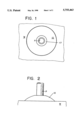
- FIG. 1 shows a front elevation of the arrangement from one side of a wall
- FIG. 2 shows a side elevation of the arrangement from one side of the wall
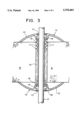
- FIG. 3 shows a cross-section through the arrangement
- the pipe P is located through a sleeve 10 which extends through a bore B in the wall W.
- the sleeve which is of a plastics material is provided with axially spaced circumferential ribs 11 on its outer surface.
- the sleeve may be cut from an extended length thereof to suit the thickness of wall to be traversed.
- Two pipe muffs 12 in the form of flanges are provided, one on each of the opposite sides of the wall W.
- Each muff 12 is in the form of a domed shell 13 having an inwardly directed centrally located annular portion 14 provided with a circumferential tooth 15 on the inner surface of the annulus.
- the muffs are located over the pipe P and pushed onto the ends of the sleeve to cause their peripheral edges to engage the wall surfaces and the teeth 15 lockingly to engage spaces between adjacent ribs 11.
- One or both ends of the sleeve 10 may be tied with a knife as necessary to lie below recesses 16 formed in the outer surfaces of the muff 12 which receive and locate sealing washers or grommets 17.
- the entire arrangement is sturdy, of neat appearance and forms an effective seal.
- one of the flanges may be integral with the sleeve.
- the sleeve need not locate a pipe or cable it may itself save as a conduit for a fluid medium.
- One or both of the flanges may be integral with other formations such as a me or grid closing the central aperture to enable the assembly of sleeve and flanges to act as a replacement for an air-brick or other vent.
- the sleeve may extend outwardly from one or both of the flanges for connection to hoses or the like.
Landscapes
- Engineering & Computer Science (AREA)
- General Engineering & Computer Science (AREA)
- Mechanical Engineering (AREA)
- Laying Of Electric Cables Or Lines Outside (AREA)
- Paper (AREA)
- Duct Arrangements (AREA)
Abstract
Description
Claims (8)
Applications Claiming Priority (3)
| Application Number | Priority Date | Filing Date | Title |
|---|---|---|---|
| GB9406362 | 1994-03-30 | ||
| GB9406362A GB9406362D0 (en) | 1994-03-30 | 1994-03-30 | Pipe muff system |
| PCT/GB1995/000558 WO1995027165A1 (en) | 1994-03-30 | 1995-03-15 | Duct passing through a wall aperture |
Publications (1)
| Publication Number | Publication Date |
|---|---|
| US5755463A true US5755463A (en) | 1998-05-26 |
Family
ID=10752792
Family Applications (1)
| Application Number | Title | Priority Date | Filing Date |
|---|---|---|---|
| US08/722,252 Expired - Fee Related US5755463A (en) | 1994-03-30 | 1995-03-15 | Duct passing through a wall aperture |
Country Status (7)
| Country | Link |
|---|---|
| US (1) | US5755463A (en) |
| EP (1) | EP0753119A1 (en) |
| JP (1) | JPH09511048A (en) |
| CN (1) | CN1147294A (en) |
| AU (1) | AU1897295A (en) |
| GB (1) | GB9406362D0 (en) |
| WO (1) | WO1995027165A1 (en) |
Cited By (11)
| Publication number | Priority date | Publication date | Assignee | Title |
|---|---|---|---|---|
| US6952929B2 (en) | 2002-06-27 | 2005-10-11 | Sanden Corporation | Air conditioning systems for vehicles, comprising such air conditioning systems, and methods for driving hybrid compressors of such air conditioning systems |
| US20110186148A1 (en) * | 2010-02-01 | 2011-08-04 | Dvorak Steven G | Escutcheon |
| US8261766B1 (en) * | 2009-10-25 | 2012-09-11 | Crescent Plumbing, Inc. | Positioning structure for assembly of a water faucet plaquette |
| US20150047719A1 (en) * | 2013-08-14 | 2015-02-19 | Luke Bolton | Multi-Fit Cover Plate |
| CN105135644A (en) * | 2015-08-31 | 2015-12-09 | 江苏知民通风设备有限公司 | Air outlet for exterior wall |
| USD755038S1 (en) * | 2014-08-13 | 2016-05-03 | Luke Bolton | Multi-fit cover plate |
| US10436369B2 (en) | 2012-08-14 | 2019-10-08 | Ductmate Industries, Inc. | High efficiency take-off fitting |
| US10591179B2 (en) | 2012-08-14 | 2020-03-17 | Ductmate Industries, Inc. | Flexible register boot for heated and cooled air |
| US11130145B2 (en) * | 2017-06-22 | 2021-09-28 | Durst Corporation, Inc. | Adjustable escutcheon assembly |
| US11231131B2 (en) * | 2018-03-14 | 2022-01-25 | Dipl.-Ing. H. Horstmann Gmbh | System for monitoring overhead lines |
| US20220297850A1 (en) * | 2021-03-17 | 2022-09-22 | The Boeing Company | Electrical pass-through assembly for traversing a structure |
Families Citing this family (13)
| Publication number | Priority date | Publication date | Assignee | Title |
|---|---|---|---|---|
| AUPN023694A0 (en) * | 1994-12-22 | 1995-01-27 | H.P.H. Pty. Ltd. | A fluid apron |
| GB9519840D0 (en) * | 1995-09-29 | 1995-11-29 | Artform Int Ltd | Ducts |
| GB9523900D0 (en) * | 1995-11-22 | 1996-01-24 | Gibbons Jonathan S | Pipe sleeve terminal |
| GB9615536D0 (en) * | 1996-07-24 | 1996-09-04 | Artform Int Ltd | Cable entry system |
| GB2322924B (en) * | 1997-03-07 | 2001-08-01 | Sankey Robert David | Duct assembly |
| GB2330389A (en) * | 1997-04-23 | 1999-04-21 | Binney Adrian Philip | Duct assembly |
| SE526317C2 (en) * | 2003-02-05 | 2005-08-23 | Roxtec Ab | Socket for cable entry, pipe entry, etc. |
| EP1837573B1 (en) | 2006-03-20 | 2012-09-12 | Beele Engineering B.V. | System for dynamically sealing a conduit sleeve through which a pipe or cable extends |
| EP2390544B1 (en) | 2010-05-25 | 2012-08-29 | Beele Engineering B.V. | An assembly and a method for providing in an opening a sealing system |
| EP2703705B1 (en) | 2012-08-30 | 2017-03-29 | Beele Engineering B.V. | Sealing system for an annular space |
| NL2010304C2 (en) | 2013-02-14 | 2014-08-18 | Beele Eng Bv | System for sealingly holding cables which extend through an opening. |
| JP6688528B2 (en) * | 2015-12-07 | 2020-04-28 | 日動電工株式会社 | Water pipe penetration part mounting member in fire hydrant box |
| CN115539716B (en) * | 2022-10-31 | 2025-08-05 | 中国一冶集团有限公司 | A concrete pump pipe conveying floor slab perforation shock-absorbing device and its construction method |
Citations (7)
| Publication number | Priority date | Publication date | Assignee | Title |
|---|---|---|---|---|
| GB1159606A (en) * | 1966-09-30 | 1969-07-30 | Anton Jensen & Co As | Pipe-Sleeve Devices |
| US4165105A (en) * | 1977-12-27 | 1979-08-21 | General Electric Company | Cabinet transition sleeve |
| US4385777A (en) * | 1980-06-02 | 1983-05-31 | The Logsdon Foundation | Decorative escutcheon capable of inhibiting the propagation of noise |
| DE3629140A1 (en) * | 1986-06-12 | 1987-12-17 | Kabelmetal Electro Gmbh | Wall lead-through for pipes, cables or lines |
| DE8912898U1 (en) * | 1989-10-28 | 1990-01-25 | Rauch, Bernhard, 1000 Berlin | Equipment for water- and gas-tight laying of cable ducts |
| DE8915213U1 (en) * | 1989-12-28 | 1990-02-08 | REHAU AG + Co, 8673 Rehau | Wall duct for pipes, cables or lines |
| DE4200866A1 (en) * | 1992-01-15 | 1993-07-22 | Siemens Ag | WALL PROTECTION FOR PIPES, CABLES, LINES OR THE LIKE |
-
1994
- 1994-03-30 GB GB9406362A patent/GB9406362D0/en active Pending
-
1995
- 1995-03-15 JP JP7525480A patent/JPH09511048A/en active Pending
- 1995-03-15 US US08/722,252 patent/US5755463A/en not_active Expired - Fee Related
- 1995-03-15 AU AU18972/95A patent/AU1897295A/en not_active Abandoned
- 1995-03-15 CN CN95192800A patent/CN1147294A/en active Pending
- 1995-03-15 WO PCT/GB1995/000558 patent/WO1995027165A1/en not_active Ceased
- 1995-03-15 EP EP95911391A patent/EP0753119A1/en not_active Withdrawn
Patent Citations (7)
| Publication number | Priority date | Publication date | Assignee | Title |
|---|---|---|---|---|
| GB1159606A (en) * | 1966-09-30 | 1969-07-30 | Anton Jensen & Co As | Pipe-Sleeve Devices |
| US4165105A (en) * | 1977-12-27 | 1979-08-21 | General Electric Company | Cabinet transition sleeve |
| US4385777A (en) * | 1980-06-02 | 1983-05-31 | The Logsdon Foundation | Decorative escutcheon capable of inhibiting the propagation of noise |
| DE3629140A1 (en) * | 1986-06-12 | 1987-12-17 | Kabelmetal Electro Gmbh | Wall lead-through for pipes, cables or lines |
| DE8912898U1 (en) * | 1989-10-28 | 1990-01-25 | Rauch, Bernhard, 1000 Berlin | Equipment for water- and gas-tight laying of cable ducts |
| DE8915213U1 (en) * | 1989-12-28 | 1990-02-08 | REHAU AG + Co, 8673 Rehau | Wall duct for pipes, cables or lines |
| DE4200866A1 (en) * | 1992-01-15 | 1993-07-22 | Siemens Ag | WALL PROTECTION FOR PIPES, CABLES, LINES OR THE LIKE |
Cited By (13)
| Publication number | Priority date | Publication date | Assignee | Title |
|---|---|---|---|---|
| US6952929B2 (en) | 2002-06-27 | 2005-10-11 | Sanden Corporation | Air conditioning systems for vehicles, comprising such air conditioning systems, and methods for driving hybrid compressors of such air conditioning systems |
| US8261766B1 (en) * | 2009-10-25 | 2012-09-11 | Crescent Plumbing, Inc. | Positioning structure for assembly of a water faucet plaquette |
| US20110186148A1 (en) * | 2010-02-01 | 2011-08-04 | Dvorak Steven G | Escutcheon |
| US10436369B2 (en) | 2012-08-14 | 2019-10-08 | Ductmate Industries, Inc. | High efficiency take-off fitting |
| US10591179B2 (en) | 2012-08-14 | 2020-03-17 | Ductmate Industries, Inc. | Flexible register boot for heated and cooled air |
| US20150047719A1 (en) * | 2013-08-14 | 2015-02-19 | Luke Bolton | Multi-Fit Cover Plate |
| USD755038S1 (en) * | 2014-08-13 | 2016-05-03 | Luke Bolton | Multi-fit cover plate |
| CN105135644A (en) * | 2015-08-31 | 2015-12-09 | 江苏知民通风设备有限公司 | Air outlet for exterior wall |
| US11130145B2 (en) * | 2017-06-22 | 2021-09-28 | Durst Corporation, Inc. | Adjustable escutcheon assembly |
| US11596967B2 (en) | 2017-06-22 | 2023-03-07 | Durst Corporation, Inc. | Adjustable escutcheon assembly |
| US11231131B2 (en) * | 2018-03-14 | 2022-01-25 | Dipl.-Ing. H. Horstmann Gmbh | System for monitoring overhead lines |
| US20220297850A1 (en) * | 2021-03-17 | 2022-09-22 | The Boeing Company | Electrical pass-through assembly for traversing a structure |
| US12117115B2 (en) * | 2021-03-17 | 2024-10-15 | The Boeing Company | Electrical pass-through assembly for traversing a structure |
Also Published As
| Publication number | Publication date |
|---|---|
| GB9406362D0 (en) | 1994-05-25 |
| JPH09511048A (en) | 1997-11-04 |
| EP0753119A1 (en) | 1997-01-15 |
| CN1147294A (en) | 1997-04-09 |
| WO1995027165A1 (en) | 1995-10-12 |
| AU1897295A (en) | 1995-10-23 |
Similar Documents
| Publication | Publication Date | Title |
|---|---|---|
| US5755463A (en) | Duct passing through a wall aperture | |
| RU2119112C1 (en) | Blocked joint between smooth end of one pipe line and end of other pipe line fitted with bell mouth | |
| US6659510B1 (en) | Pipe-end-connecting joint | |
| US4480860A (en) | Transition coupling and clamp assembly containing same | |
| JP6248899B2 (en) | Wire harness seal structure | |
| KR920001117A (en) | Pipe coupling | |
| ES2165527T3 (en) | IMPROVED COUPLING FOR FLUID DUCTS. | |
| US6194659B1 (en) | Cable entry device | |
| US3490791A (en) | Pipe connector | |
| EP0862254B1 (en) | Cable sealing | |
| JPS635631B2 (en) | ||
| EP3814662B1 (en) | A lead-through comprising a seal and an outer diameter extender | |
| KR960018268A (en) | Plastic reservoir | |
| GB2075141A (en) | Pipe joints and pipe couplings | |
| US5000489A (en) | Service saddle | |
| GB2306200A (en) | Duct extending through wall or partition aperture | |
| US2893760A (en) | Pipe coupling including elastomeric covered clamping means | |
| ES2054534A2 (en) | Branch connector for connection between a main flexible pipe and a secondary flexible pipe | |
| EP1113553B1 (en) | Liquid-tight coupling | |
| JP2004222471A (en) | Sealing structure of cab for construction equipment | |
| JPH07208667A (en) | Steel pipe fittings | |
| US6887037B1 (en) | Boat impeller seal assembly | |
| JPS5917997Y2 (en) | deodorant ring | |
| JP5308697B2 (en) | Tube cap body | |
| ES2092892T3 (en) | PIPE EXTENSION FOR A FILTER BOX WITH A RETURN FILTER. |
Legal Events
| Date | Code | Title | Description |
|---|---|---|---|
| AS | Assignment |
Owner name: ARTFORM INTERNATIONAL LIMITED, UNITED KINGDOM Free format text: ASSIGNMENT OF ASSIGNORS INTEREST;ASSIGNOR:DAVIDSON, PAUL;REEL/FRAME:008336/0393 Effective date: 19961001 |
|
| AS | Assignment |
Owner name: POLYSLEEVE PRODUCTS LIMITED, UNITED KINGDOM Free format text: ASSIGNMENT OF ASSIGNORS INTEREST;ASSIGNOR:ARTFORM INTERNATIONAL LIMITED;REEL/FRAME:009781/0550 Effective date: 19981205 |
|
| FPAY | Fee payment |
Year of fee payment: 4 |
|
| SULP | Surcharge for late payment | ||
| REMI | Maintenance fee reminder mailed | ||
| REMI | Maintenance fee reminder mailed | ||
| LAPS | Lapse for failure to pay maintenance fees | ||
| STCH | Information on status: patent discontinuation |
Free format text: PATENT EXPIRED DUE TO NONPAYMENT OF MAINTENANCE FEES UNDER 37 CFR 1.362 |
|
| FP | Lapsed due to failure to pay maintenance fee |
Effective date: 20060526 |