US5748416A - Magnetoresistive playback head - Google Patents
Magnetoresistive playback head Download PDFInfo
- Publication number
- US5748416A US5748416A US08/821,182 US82118297A US5748416A US 5748416 A US5748416 A US 5748416A US 82118297 A US82118297 A US 82118297A US 5748416 A US5748416 A US 5748416A
- Authority
- US
- United States
- Prior art keywords
- film
- thickness
- magnetoresistive
- permanent magnet
- bilayer
- Prior art date
- Legal status (The legal status is an assumption and is not a legal conclusion. Google has not performed a legal analysis and makes no representation as to the accuracy of the status listed.)
- Expired - Lifetime
Links
Images


Classifications
-
- G—PHYSICS
- G11—INFORMATION STORAGE
- G11B—INFORMATION STORAGE BASED ON RELATIVE MOVEMENT BETWEEN RECORD CARRIER AND TRANSDUCER
- G11B5/00—Recording by magnetisation or demagnetisation of a record carrier; Reproducing by magnetic means; Record carriers therefor
- G11B5/127—Structure or manufacture of heads, e.g. inductive
- G11B5/33—Structure or manufacture of flux-sensitive heads, i.e. for reproduction only; Combination of such heads with means for recording or erasing only
- G11B5/39—Structure or manufacture of flux-sensitive heads, i.e. for reproduction only; Combination of such heads with means for recording or erasing only using magneto-resistive devices or effects
- G11B5/3903—Structure or manufacture of flux-sensitive heads, i.e. for reproduction only; Combination of such heads with means for recording or erasing only using magneto-resistive devices or effects using magnetic thin film layers or their effects, the films being part of integrated structures
- G11B5/3906—Details related to the use of magnetic thin film layers or to their effects
- G11B5/3929—Disposition of magnetic thin films not used for directly coupling magnetic flux from the track to the MR film or for shielding
- G11B5/3932—Magnetic biasing films
-
- G—PHYSICS
- G11—INFORMATION STORAGE
- G11B—INFORMATION STORAGE BASED ON RELATIVE MOVEMENT BETWEEN RECORD CARRIER AND TRANSDUCER
- G11B5/00—Recording by magnetisation or demagnetisation of a record carrier; Reproducing by magnetic means; Record carriers therefor
- G11B5/127—Structure or manufacture of heads, e.g. inductive
- G11B5/33—Structure or manufacture of flux-sensitive heads, i.e. for reproduction only; Combination of such heads with means for recording or erasing only
- G11B5/39—Structure or manufacture of flux-sensitive heads, i.e. for reproduction only; Combination of such heads with means for recording or erasing only using magneto-resistive devices or effects
- G11B5/3903—Structure or manufacture of flux-sensitive heads, i.e. for reproduction only; Combination of such heads with means for recording or erasing only using magneto-resistive devices or effects using magnetic thin film layers or their effects, the films being part of integrated structures
Definitions
- the present invention relates to a magnetoresistive playback head (MR head) for reading magnetic data signals from a magnetic recording medium.
- the present invention relates a structure for an MR head wherein a permanent magnet film disposed to apply a longitudinal-bias magnetic field can generate adequate coercive force even at a thickness as thin as of approximately 50 Angstroms or less.
- Magneticoresistance is the effect of a magnetic material carrying electric current in the presence of a magnetic field where the material has increased resistivity when the field is parallel to the current flow and decreased resistivity when the field is at right angles to the current flow.
- Magnetic flux density is the amount of magnetic flux per square cm over a small area at a given point. The direction of the flux is at right angles to that area.
- Magnetic flux is the phenomenon produced in the medium surrounding electric currents or magnets. The amount of magnetic flux through any area is measured by the quantity of electricity caused by flow in an electric circuit of a given resistance bounding the area when this circuit is removed from the magnetic field.
- the curve showing the ferromagnetic characteristics of a material in which the magnetic flux density, B, is plotted against the magnetic force, H, is called the "magnetization curve.”
- Retentivity is the property measured by the residual induction corresponding to the saturation induction for a magnetic material.
- saturation induction is the maximum intrinsic magnetic induction possible in a material. The ratio of retentivity to saturation flux density is called the "squareness ratio”.
- the magnetic film of the present invention has a high squareness ratio that serves to eliminate Barkhausen noise, thus making the MR head optimal for applications involving narrow tracks.
- An MR head is a dedicated playback head that takes advantage of the magnetoresistive effect of ferromagnetic films to detect signals.
- the playback properties are independent of the relative speed between the head and the magnetic recording medium such as, for example, a disc.
- MR heads have high sensitivity. These properties have made MR heads the focus of attention as a playback head that can meet the increasing demand for more compact magnetic disk devices and the increasing demand for heads able to utilize such devices' requisite higher recording densities. Thus, the development of MR heads has been quite active.
- FIG. 13 there is shown a cross-section perspective drawing of a typical recording/playback head with an incorporated MR head playback head and an inductive recording head.
- the head is structured with separate playback and recording sections.
- An MR head 2 is formed on a substrate 7, and then an induction head 1 is mounted to write data onto a magnetic recording medium.
- a stacked stripe 20 comprises a Soft Adjacent Layer (“SAL") film 13 which is a soft-magnetic bias film, a shunt film 12, and an MR (magnetoresistive) film 11.
- SAL Soft Adjacent Layer
- stacked stripe 20 is disposed between a lower shield layer 52 and a mid-shield layer 51 via a lower insulating layer 42 and an upper insulating layer 41.
- a permanent magnet film 21 and an electrode film 31 are formed on either side of stacked stripe 20.
- magnetic data signals on the magnetic recording medium passing by MR head 2 are detected by a playback gap 9 formed by upper insulating layer 41 and lower insulating layer 42. This generates a change in electrical resistance in MR film 11 of stacked stripe 20, which is converted into an electrical signal.
- an upper induction head 1 is used, and a magnetic circuit is formed from mid-shield 51 and an upper electrode 3.
- a magnetic field is generated at the recording gap. This results in data being written to the magnetic recording medium, such as a disc.
- MR film 11 is formed using thin-film formation technology such as through sputtering a ferromagnetic material. NiFe alloys (permalloys), CoFe alloys, and the like are generally used.
- bias magnetic fields in different directions are needed for MR heads to perform optimal playback.
- One of the two bias fields is a transverse bias field for setting the active point of the MR film at a region where the magnetoresistive effect is linear. This results in a linear response to the leakage field from the signal of the magnetic recording medium.
- the other of the two bias fields is a longitudinal bias field that is generated longitudinally to the MR film. The purpose of this bias field is to apply and set a magnetic field in one direction of the MR film, thus providing smooth rotation of magnetization and limiting discontinuous rotation of magnetization.
- Another benefit of the longitudinal bias field is that Barkhausen noise is limited by keeping fixed the magnetic zones which tend to be generated at the ends of the MR film.
- FIG. 14 there is shown an example of a SAL bias, which is one method for generating a transverse bias field.
- a soft magnetic film is disposed near MR film 11.
- a sensing current is applied to the MR film, and the resulting magnetic field magnetizes SAL film 13.
- the magnetic field from the magnetized SAL film results in a bias field at the MR film.
- This transverse bias field is substantially perpendicular to the surface of the magnetic medium and is substantially parallel to the thickness of the MR film.
- the other bias field is generated longitudinally to the MR film.
- a hard-bias MR head was developed, whereby permanent magnets are disposed on either end of the MR film.
- permanent magnet films 21 are disposed on both sides of stacked stripe 20. In this method, permanent magnet films 21 are formed on top of MR film 11. This geometry creates an overlap of the permanent magnet film and the MR film at the ends of the magnetic sensing region, resulting in thicker ends and limiting the ability to narrow the playback gap.
- the length of the magnetic sensing region is 10 microns or more.
- Japanese Laid-Open Publication Number 4-245011 incorporated herein by reference in its entirety, disclosed a similar method for generating a bias field using a permanent magnet film.
- this disclosure involves a structure in which a permanent magnet film is stacked on an MR film.
- Co:80, Pt:20 (atom %) with a thickness of 1000 Angstroms would be desirable, and that a thicker film will provide a stabilized magnetic zone even if an alloy composition with a low residual flux density is used. It is also stated that this composition was chosen simply because a high coercive force was obtained.
- the playback MR head has been effective to read current modest areal densities.
- MR heads with playback gap lengths of approximately 0.4 microns are used for surface recording densities of 650 Mb/in 2 .
- this playback gap length will become narrower and narrower.
- the thickness of the permanent magnet film must be decreased as the playback gap length decreases.
- the MR head of the present invention uses a different structure from the prior art described above.
- the present invention uses permanent magnet films bonded at the ends of the MR film, as disclosed in Japanese laid-open publication number 3-125311, the entirety of which is incorporated herein by reference.
- the geometry of the permanent magnet film at the ends of the MR film in this type of structure is believed to be suited for heads with narrow playback gaps.
- none of the prior art technologies discloses the optimal structure for MR heads that is allowed by using permanent magnet films as disclosed in the present application.
- the prior art does not describe or suggest such vital issues as the specific geometric and alloy chemistry means, provided by the present invention, for restricting Barkhausen noise in SAL-type magnetoresistive heads for use with narrow playback tracks and playback gaps.
- the present invention described below has a similar magnitude for coercive force, but the residual flux density is in a completely different range, and there is no description of the specific composition of the CoCrPt of the present invention. Further, the article specifically states that with CoCrPt films of 200 Angstroms or less, the bias field is not adequate for limiting Barkhausen noise. According to the known technology presented in the article, there is no indication or suggestion of how to restrict Barkhausen noise when the CoCrPt film is made as thin as required by the new data storage technology.
- a method that is frequently used for decreasing the playback gap is to make either the upper insulating layer or the lower insulating layer thinner.
- the electrode film at the ends of the track are necessarily raised up. This makes it easy for an electrical short to occur between the electrode film and the mid-shield layer. In order to avoid this problem, it is necessary to select an appropriately thicker thickness for the permanent magnet film than what signal considerations would call for.
- the bias field itself it would be desirable for the bias field itself to be applied only to the MR film. If the permanent magnet film is thick, the magnetic flux can bypass to sections close to the MR film, such as the upper insulating layer. This would disturb the signal flux received from the magnetic recording medium, and could result in noise or in distortions in the output waveform. Therefore, it is necessary to have a structure that applies the magnetic field only to the MR film or spilling over only to a region very close to the MR film, even if the MR film is very thin, thus preventing magnetic field leakage from the permanent magnet film from disturbing the signal field from the magnetic recording medium.
- the spin-valve MR element involves basically the same issues as the SAL element shown in FIG. 14.
- a stacked stripe 20' comprises an anti-ferromagnetic film 14, a fixed magnetic film 18, a magnetic separator film 17, and a movable magnetic film (MR film) 11 all disposed above a lower insulating layer 42.
- This type of element uses the giant magnetoresistive effect, and in this case it would also be desirable to have the bias field from the permanent magnet film be applied only to the MR film (corresponding to the movable magnetic film).
- the thickness of the movable magnetic film would be 50-100 Angstroms or less. Even if the movable magnetic film is formed this thin, it is still necessary to have an adequate magnetic field applied exclusively to the film.
- the object of the present invention is to provide a bias-type MR head using a permanent magnet film to handle narrow recorded tracks and provide a narrow gap so that recording density can be increased.
- a magnetic head is provided that is highly sensitive and that limits Barkhausen noise by optimizing the magnetic properties of the permanent magnet film.
- a SAL-type magnetoresistive head the following layers are stacked on a lower insulating layer: a soft magnetic bias film, a magnetic separation film (shunt film), a magnetoresistive film (MR film), and an upper insulating layer.
- the outer side of the playback track of the MR film is in direct contact with the permanent magnet film or in indirect contact via a base film.
- the following layers are stacked on a lower insulating layer: an anti-ferromagnetic film, a fixed magnetic film, a magnetic separating film, a movable magnetic film (MR film), and an upper insulating film.
- the outer side of the movable magnetic film is in direct contact with the permanent magnet film or in indirect contact via a base film.
- the permanent magnet film used to apply the longitudinal bias field for the MR head of the present invention, is formed from a CoCrPt alloy with a composition of: 65-82 atom % Co; 10-15 atom % Cr; and 8-20 atom % Pt. This provides adequate output and limitation of Barkhausen noise even with a playback track width of 3 microns or less and a playback gap length of 0.2 microns or less.
- a base film for the permanent magnet film can be formed from Cr, W, or Mo or an alloy thereof with a thickness of approximately 50-200 Angstroms.
- an SAL-type magnetoresistive playback head that is highly sensitive and that limits Barkhausen noise is provided by optimizing the magnetic properties of the permanent magnet film.
- a soft magnetic bias film SAL film
- a magnetic separating film shunt film
- MR film magnetoresistive film
- an upper insulating layer On top of a lower insulating layer are stacked a soft magnetic bias film (SAL film), a magnetic separating film (shunt film), a magnetoresistive film (MR film), and an upper insulating layer, in that order.
- the outer sides of the track of the MR film are in direct contact with the permanent magnet film or in indirect contact via a base film.
- the present invention relates to a spin-valve magnetoresistive playback head.
- a lower insulating layer On top of a lower insulating layer are stacked an anti-ferromagnetic film, a fixed magnetizing film, a magnetic separating film, a movable magnetizing film (MR film), and an upper insulating layer, in that order.
- the outer sides of the track of the movable magnetizing film are in direct contact with the permanent magnet film or in indirect contact via a base film.
- Barkhausen noise is eliminated by using a CoCrPt alloy film having a composition that provides the magnetic properties needed for a permanent magnet film that can handle narrow tracks and narrow gaps, and by specifying a ratio between the thicknesses of the MR film and the permanent magnet film.
- a magnetoresistive playback head comprises a magnetoresistive film having a first thickness, a shunt film on the magnetoresistive film, the shunt film having a second thickness, a soft magnetic bias film on the shunt film, the shunt film in a sandwich relationship between the magnetoresistive film and the soft magnetic bias film, the soft magnetic bias film having a third thickness, a stacked stripe comprising the magnetoresistive film, the shunt film, and the soft magnetic bias film, the stacked stripe having a transverse direction across the first, second, and third thicknesses, and a longitudinal direction substantially orthogonal to the transverse direction, the stacked stripe having a first end and a second end at the longitudinal direction, a permanent magnet film, an electrode film disposed on the permanent magnet film to form a bilayer stacked in the transverse direction, the stacked stripe is disposed with the bilayer at each of the first and second ends, an upper insulating layer disposed over the stacked strip
- a magnetoresistive playback head comprises an anti-ferromagnetic film having a first thickness, a fixed magnetizing film having a second thickness, a magnetic separation film having a third thickness, and a movable magnetizing film having a fourth thickness stacked sequentially to form a stacked stripe;
- the movable magnetizing film is a magnetoresistive film;
- the stacked stripe having a transverse direction across the first, second, third, and fourth thicknesses, and a longitudinal direction substantially orthogonal to the transverse direction, the stacked stripe having a first end and a second end at the longitudinal direction, a permanent magnet film, an electrode film disposed on the permanent magnet film to form a bilayer stacked in the transverse direction
- the stacked stripe is disposed with the bilayer at each of the first and second ends, an upper insulating layer disposed over the stacked stripe and the bilayer at each of the first and second ends, a lower insulating layer disposed under the stacked stripe and the bi
- a magnetoresistive playback head comprises a magnetoresistive film having a first thickness, a shunt film on the magnetoresistive film, the shunt film having a second thickness, a soft magnetic bias film on the shunt film, the shunt film in a sandwich relationship between the magnetoresistive film and the soft magnetic bias film, the soft magnetic bias film having a third thickness, a stacked stripe comprises the magnetoresistive film, the shunt film, and the soft magnetic bias film, the stacked stripe having a transverse direction across the first, second, and third thicknesses, and a longitudinal direction substantially orthogonal to the transverse direction, the stacked stripe having a first end and a second end at the longitudinal direction, a permanent magnet film, an electrode film disposed on the permanent magnet film to form a bilayer stacked in the transverse direction, the stacked stripe is disposed with the bilayer at each of the first and second ends, a base film disposed between each of the first and second ends
- a magnetoresistive playback head comprises an anti-ferromagnetic film having a first thickness, a fixed magnetizing film having a second thickness, a magnetic separation film having a third thickness, and a movable magnetizing film having a fourth thickness stacked sequentially to form a stacked stripe;
- the movable magnetizing film is a magnetoresistive film;
- the stacked stripe having a transverse direction across the first, second, third, and fourth thicknesses, and a longitudinal direction substantially orthogonal to the transverse direction, the stacked stripe having a first end and a second end at the longitudinal direction, a permanent magnet film, an electrode film disposed on the permanent magnet film to form a bilayer stacked in the transverse direction
- the stacked stripe is disposed with the bilayer at each of the first and second ends, a base film disposed between each of the first and second ends and the bilayer, the base film extending along a surface of the bilayer at each of the first and second ends, an upper insul
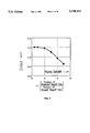
- FIG. 1 shows the relationship between the film thickness and the coercive force property in the permanent magnet film of the present invention.
- FIG. 2 is a three coordinate diagram showing the three factors relating to the permanent magnet film.
- FIG. 3 shows the relationship between playback track width and output properties.
- FIG. 4 shows the relationship between playback track width and Barkhausen noise.
- FIG. 5 shows the relationship between film thickness ratio and output properties in SAL-type MR heads.
- FIG. 6 shows the relationship between film thickness ratio and Barkhausen noise in spin-valve MR heads.
- FIG. 7 shows the relationship between film thickness ratio and output properties in spin-valve MR heads.
- FIG. 8 shows the relationship between film thickness ratio and Barkhausen noise in spin-valve MR heads.
- FIG. 9 shows the relationship between the (B r •t) product and output properties.
- FIG. 10 shows the relationship between the (B r •t) product and Barkhausen noise properties.
- FIG. 11 is a drawing showing the distribution of coercive force and Barkhausen noise in relation to the coercive force squareness ratio.
- FIG. 12 is a cross-section drawing of an MR head according to an embodiment of the present invention.
- FIG. 13 is a cross-sectional perspective drawing of a conventional head with separate read and write sections.
- FIG. 14 is a cross-section drawing of a conventional SAL-type MR head.
- FIG. 15 is a cross-section drawing of a conventional spin-valve MR head.
- FIG. 16 is a drawing for the purpose of explaining the coercive force squareness ratio.
- the present invention innovatively provides a structure that specifies the unexpected ratio range between the thicknesses of the permanent magnet film and the MR film, previously unknown, in an MR head wherein the two ends of the stacked stripe are in direct or indirect contact with the permanent magnet film and wherein the playback track width is 3 microns or less and the playback gap length is 0.3 microns or less.
- the inventors of the present invention began with the prior art disclosed in Japanese laid-open publication number 3-125311 and performed detailed investigations regarding the magnetic properties of the permanent magnet film in order to overcome inherent failings in 3-125311 when the playback track width is made narrower than about 3 microns and when the playback gap length is 0.3 microns or less.
- the present invention is useful in SAL-type magnetoresistive heads or spin-valve magnetoresistive heads where the playback track is 3 microns or less and the playback gap length is 0.2 microns or less.
- the signal field from the magnetic recording medium is applied more or less only to the MR film even if the MR film is thick or the permanent magnet film on either end is relatively thick.
- there is little magnetic field leakage outside the MR film and the magnetic field from the magnetic recording medium is not disrupted.
- the permanent magnet film becomes thicker relative to the MR film. This results in magnetic flux leakage from portions not in contact with the MR film, and can lead to noise.
- the present invention provides that if the thickness of the permanent magnet film is no more than three times the thickness of the MR film, preferably 0.5-3 times, then the decrease in output is slight and almost all Barkhausen noise can be eliminated.
- a thick permanent magnet film results in a narrow playback gap, thus decreasing the distance between the permanent magnet film and the shield. This can result in an electrical short. If the permanent magnet film can be made thin enough, electrical insularity can be maintained. It is a failure of the known CoCrPt composition (the composition having a low B r of 9000 G or less from IEEE Trans. Mag., vol. 31 pp. 2612-2614), that H c decreases dramatically as the permanent magnet film is made thinner. Consequently, the properties of the permanent magnet film becomes inadequate. With the CoCrPt alloy composition of the present invention, it is possible to obtain a high coercive force H c of 700 Oe or more even when the film is thin, and a stable bias field for limiting Barkhausen noise is easily obtained.
- the present invention provides a high coercive force squareness ratio S* that serves to limit Barkhausen noise, and provides that a range of 0.60-0.85 is preferable.
- H c1 is the X component (magnetic field H) of the interval between the origin and the intersection of a tangent line 12 and a parallel line 13 passing through a residual magnetization M r .
- S* represents the slope of the magnetization curve at the coercive force. If this S* value is large, the flux reversal is quick and occurs all at once.
- the permanent magnet film that is applying a bias field to the MR film can also be influenced by the magnetization of the MR film in return.
- the magnetic interaction of the permanent magnet film is high (when S* is large)
- any magnetic particles adjacent to the magnetized permanent magnet film will also be magnetized, diluting or distorting the field of the permanent magnet film, and the magnetic field strength generated by the permanent magnet will be weakened.
- the magnetic interaction of the permanent magnet film is low (when S* is small)
- the magnetic particles adjacent to the magnetic particles of the permanent magnet film will be themselves difficult to magnetize, and the magnetic field strength generated by the permanent magnet will not be weakened.
- S* since S* is small in this case, the actual magnetization that takes place at the active point will be less, as in standard permanent magnet material, and an adequate magnetic field will not be applied.
- S* must be controlled to be within a certain range of values.
- S* can be controlled using sputtering conditions, such as Ar gas pressure and bias voltage.
- sputtering conditions such as Ar gas pressure and bias voltage.
- a magnetron sputtering device was used to control S* within the range of 0.60-0.85 by having Ar gas pressure be at least 10 mTorr and by having the bias voltage be at least -50 V.
- Cr film, Mo film, or the like can be used as a base for the permanent magnet of the present invention. With these base films, it is possible to control H c and S* of the CoCrPt film by changing the crystal orientation or the crystal particle diameter.
- FIG. 2 there is shown how residual flux density B r and coercive force H c are dependent on the composition of the CoCrPt alloy film of the present invention. The relationship in comparative examples are also shown.
- the present invention comprises a composition range for this as Co: 65-82 atom %, Cr: 10-15 atom %, and Pt: 8-20 atom %.
- the CoCrPt alloys within the composition range of the present invention can provide high coercive force where conventional compositions cannot.
- a structure for an MR element was constructed in the following manner to verify the effect of the permanent magnet film of the present invention.
- a SAL film (Ni--Fe--Cr film) 13 and a shunt film (Ta film) 12 are surrounded on either side by a base film (Cr film) 22, a permanent magnet film (CoCrPt alloy film) 21, and an MR film (Ni--Fe alloy film) 11, which are stacked on a lower shield layer (Fe--Al--Si alloy film) 52 via a lower insulating layer (Al 2 O 3 film).
- an electrode film (Ni--Fe--Ta alloy film) 31 an upper insulating film 41, and a mid-shield film 51.
- the present invention provides a bias to MR film 11 using the same method as the one disclosed in Japanese laid-open publication number 3-125311. Accordingly, the magnetically sensitive region is biased with both a longitudinal bias and a transverse bias.
- the longitudinal bias is generated parallel to MR film 11.
- the transverse bias is generated by shunt film 12 and SAL film 13, which are parallel to MR film 11.
- the thickness of MR film 11 was varied in the range of 50-200 Angstroms
- the thickness of permanent magnet film 21 was varied in the range of 25-600 Angstroms
- the thickness of shunt film 12 was set to 100 Angstroms.
- An Fe--Al--Si alloy was used for the lower shield layer.
- Al 2 O 3 was used for the upper and lower insulating layer.
- a Ni--Fe--Cr alloy was used for the SAL film.
- Ta or Nb was used for the shunt film.
- Cr, W, or Mo was used for the base film.
- a CoCrPt alloy was used for the permanent magnet film.
- a Ni--Fe alloy was used for the MR film.
- a Ni--Fe--Ta or Mo--Au alloy was used for the electrode film.
- the composition of the CoCrPt alloy By changing the composition of the CoCrPt alloy, the residual flux density of the permanent magnet film could be controlled within the range of 5400-14000 G, and comparative studies were performed.
- Coercive force H c and coercive force squareness ratio S* were changed by controlling the composition of the CoCrPt film and the thickness of the base film.
- An inductive head 1 formed on MR head 2 was used to record on a magnetic recording medium, and the playback properties of the MR head were studied.
- the track width of inductive head 1 was set to 7 microns. Barkhausen noise was observed as follows. First, the recording and playback processes were repeated twenty times and the playback waveforms were observed on an oscilloscope. In this repeated measurement, the waveforms were visually observed for obvious changes in peak values, jumps in the waveform, and baseline shifts. If any of these were noticed, it was assumed that Barkhausen noise was generated by the sample head. A Barkhausen elimination ratio was defined as (the number of times Barkhausen noise was not observed)/(the number of measurements) In these cases, as described above, the number of measurements were twenty.
- the composition is Co:74, Cr:18, Pt:8 (atom %), with a B r of approximately 6000 G for the residual flux density.
- an alloy of Co:76, Cr:12, Pt:12 (atom %) with a B r of approximately 11000 G is used.
- the output for narrower track widths and the rates of elimination of Barkhausen noise was compared.
- the width of the playback track was varied from 7 microns to 0.1 microns.
- the playback gap length was fixed at 0.2 microns.
- the MR membrane was set to 100 ⁇ and the permanent magnet membrane was set to 200 ⁇ .
- the prior art example using Co:74, Cr:18, Pt:8 showed a coercivity H c of 600 Oe.
- the coercivity was 1700 Oe.
- the product of the residual flux density and the membrane thickness (BR ⁇ t) was 120 Gmicrons and 220 Gmicrons respectively.
- the output from the composition of the prior art example is higher for both wider and narrower playback track widths from 7 microns to 0.1 microns. This is believed to be due to the fact that the smaller B r ⁇ t of the composition of the prior art example results in a higher sensitivity.
- the output diminishes as the track width is narrowed. This is due to the fact that as the permanent magnet membranes approach each other, the magnetic field applied to the MR membrane becomes stronger and sensitivity decreases.
- the thickness of the permanent magnet membrane made the same as in this embodiment, the present invention was compared to the prior art example. It was possible that a problem would arise if the sensitivity would decrease because the use of the alloy of the present invention would provide a larger B r ⁇ t than the prior art example. However, even when the playback track width was narrowed to 0.1 micron, an adequate output was obtained, so this was not a problem.
- Barkhausen noise can be completely eliminated for track widths between 7 microns and 0.1 microns.
- the narrower the track width is made the rate of elimination of Barkhausen noise improves gradually, but Barkhausen noise is not adequately eliminated even at 0.1 microns. This is believed to be because with the present invention the coercivity of the permanent magnetic membrane is high, at 1700 Oe, whereas the coercivity is low, at 600 Oe, for the prior art composition.
- the state of magnetization of the permanent magnet membrane is influenced in the prior art example by the magnetic field from the recording medium and the magnetic field from the MR membrane.
- Barkhausen noise cannot be eliminated when the permanent magnet membrane is made thin since high coercivity cannot be obtained.
- the SAL-type MR head indicated in Embodiment 1 was made and tests were done for different thicknesses of the permanent magnet film and of the MR film. As a result, it was found that the ratio of these thicknesses influenced the output and Barkhausen noise.
- the ratio s is defined here as the thickness of the permanent magnet film/the thickness of the MR film.
- the playback track width is 2 microns and the playback gap length is 0.2 microns.
- a spin-valve MR element was prepared.
- the element was combined with an inductive head. Recording and playback functions were performed as in the example above. The output and the Barkhausen noise elimination rate were studied. Also, Barkhausen noise was evaluated based on the same standards as those used in Embodiment 1.
- a lower shield layer (an Fe--Al--Si alloy film) 52 is formed a lower insulation layer (Al 2 O 3 film) 42 on which is stacked an anti-ferromagnetic film (Fe--Mn film) 14, a base film (Cr film) 15, a fixed magnetization film (NiFe film) 13, a magnetic separation film (Cu film) 12, and a movable magnetization film (NiFe film) 11.
- a permanent magnet film (CoCrPt alloy film) 21 is formed on either side of this stack.
- An electrode film (Ni--Fe--Ta alloy film) 31 is then formed.
- a mid-shield film 51 is formed above an upper insulating film 41. Longitudinal bias is generated parallel to movable magnetization film 11.
- the thickness of the MR film (movable magnetization film 11) was set to 50 Angstroms, the thickness of permanent magnet film 21 was varied within the range 10-300 Angstroms, and magnetic separator film 12 was set to 20 Angstroms.
- An Fe--Al--Si alloy was used for the lower shield.
- Al 2 O 3 was used for the upper and lower insulating layers.
- Cr or Mo was used for the base film.
- a CoCrPt alloy was used for the permanent magnet film.
- a Ni--Fe--Ta alloy was used for the electrode film.
- the spin-valve MR head can eliminate Barkhausen noise for r in the range of 0.5-3.
- the output decreases as r increases. This might be because in the spin-valve head the magnetic field from the permanent magnet film is not applied only to the movable magnetization film but also leaks to the region around the movable magnetization film, thereby influencing the signal field from the medium.
- a SAL-type MR head was prepared as in Embodiment 1.
- the product of the residual flux density and thickness, (B r •t), of the permanent magnet film was studied.
- the permanent magnet film comprised a Co:70 atom %, Cr:14 atom %, Pt:14 atom % alloy with a B r of approximately 9000 G.
- the playback track width was 1.5 microns and the playback gap length was 0.2 microns.
- FIG. 9 and FIG. 10 there are shown the changes in output and Barkhausen noise elimination in relation to different values of the (B r •t product.
- the output decreases gradually, and then decreases rapidly at 500 Gmicrons or more. It is also seen that Barkhausen noise was not found at 200 Gmicrons or higher. The results from this study indicate that a high output can be obtained and Barkhausen noise can be eliminated for a (B r •t) product in the range of 200-500 Gmicrons.
- a SAL-type MR head as in Embodiment 1 was prepared. A study was performed on the effect on Barkhausen noise of the coercive force H c of the permanent magnet film and the coercive force squareness ratio S*. A Co:76, Cr:12, Pt:12 (atom %) alloy having a B r of approximately 11000 G was used for the permanent magnet film. The playback track width was set to 1 micron and the playback gap length was set to 0.15 microns.
- FIG. 11 there is shown a graph indicating the H c and S* of the permanent magnet film as it relates to the presence of Barkhausen noise. It was found the Barkhausen noise is effected not only by S* but also by H c . Noise is eliminated only for a value of H c of 700 Oe or more, and for the range of S* of 0.60-0.85. Barkhausen noise cannot be eliminated solely with a high Hc. An appropriate S* value must be used as well.
- FIG. 12 there is shown a cross-section drawing of an MR head as seen from the magnetic recording medium according to an embodiment of the present invention.
- the playback gap can be made at an approximately fixed distance interval since the permanent magnet film can be made much thinner than in conventional heads.
- the magnetic film are made thick so that a sufficiently large longitudinal bias field could be obtained. This thickness causes the electrode film to project into the playback gap, thereby resulting in the playback gap being forced to curve upward as shown in FIG. 14 or FIG. 15.
- the playback output would be decreased.
- permanent magnet film 21 can be formed at or below the level of MR film 13.
- an MR head for narrow tracks can be formed without making electrode film 31 thin as can be seen by comparing FIG. 12 to FIG. 14 or 15.
- FIG. 12 shows that playback gap 9 of the present invention is just the thickness of upper insulating layer 41, SAL film 13, shunt film 12, MR film 11, and lower insulating film 42.
- the conventional playback gap as shown in FIG. 14 or 15, requires that playback gap 9 be thicker by the thickness of electrode film 31.
- An equivalent spin-valve MR head is not shown but is similar to FIG. 12 except that the stacked stripe of the SAL-type head is replaced with that of the spin-valve MR head.
- a SAL-type or spin-valve MR head using the bias method with a permanent magnet can eliminate Barkhausen noise and provide high sensitivity when the CoCrPt alloy of the present invention is used.
- This advantageous combination of absence of Barkhausen noise while maintaining high sensitivity is achieved by optimizing the thickness and the magnetic properties of the permanent magnet film through the selection of the CoCrPt alloy composition of the present invention that has a squareness ratio particularly appropriate for narrow gaps.
Abstract
Description
Claims (26)
Priority Applications (2)
| Application Number | Priority Date | Filing Date | Title |
|---|---|---|---|
| US08/821,182 US5748416A (en) | 1997-03-19 | 1997-03-19 | Magnetoresistive playback head |
| JP10000383A JPH10269531A (en) | 1997-03-19 | 1998-01-05 | Magneto-resistive playback head |
Applications Claiming Priority (1)
| Application Number | Priority Date | Filing Date | Title |
|---|---|---|---|
| US08/821,182 US5748416A (en) | 1997-03-19 | 1997-03-19 | Magnetoresistive playback head |
Publications (1)
| Publication Number | Publication Date |
|---|---|
| US5748416A true US5748416A (en) | 1998-05-05 |
Family
ID=25232732
Family Applications (1)
| Application Number | Title | Priority Date | Filing Date |
|---|---|---|---|
| US08/821,182 Expired - Lifetime US5748416A (en) | 1997-03-19 | 1997-03-19 | Magnetoresistive playback head |
Country Status (2)
| Country | Link |
|---|---|
| US (1) | US5748416A (en) |
| JP (1) | JPH10269531A (en) |
Cited By (23)
| Publication number | Priority date | Publication date | Assignee | Title |
|---|---|---|---|---|
| US5867351A (en) * | 1997-07-25 | 1999-02-02 | International Business Machines Corporation | Spin valve read head with low moment, high coercivity pinning layer |
| US6040962A (en) * | 1997-05-14 | 2000-03-21 | Tdk Corporation | Magnetoresistive element with conductive films and magnetic domain films overlapping a central active area |
| US6111722A (en) * | 1997-05-07 | 2000-08-29 | Kabushiki Kaisha Toshiba | Magnetoresistance effect element having improved biasing films, and magnetic head and magnetic recording device using the same |
| US6118624A (en) * | 1997-05-07 | 2000-09-12 | Kabushiki Kaisha Toshiba | Magneto-resistance effect element having a magnetic biasing film |
| US6122151A (en) * | 1997-06-06 | 2000-09-19 | Alps Electric Co., Ltd. | Spin-valve magnetoresistive element |
| US6146776A (en) * | 1997-05-07 | 2000-11-14 | Kabushiki Kaisha Toshiba | Magneto-resistance effect head |
| US6190764B1 (en) | 1998-11-23 | 2001-02-20 | Read-Rite Corporation | Inductive write head for magnetic data storage media |
| US6221218B1 (en) | 1998-11-23 | 2001-04-24 | Read-Rite Corporation | Method of forming an inductive write head for magnetic data storage media |
| US6353318B1 (en) | 2000-03-10 | 2002-03-05 | Read-Rite Corporation | Magnetoresistive sensor having hard biased current perpendicular to the plane sensor |
| US6452765B1 (en) | 1998-11-18 | 2002-09-17 | Read-Rite Corporation | CoNbTi as high resistivity SAL material for high-density MR |
| US6462920B1 (en) | 1998-12-23 | 2002-10-08 | Read-Rite Corporation | Method and system for reducing MR head instability |
| US6496334B1 (en) | 2000-05-26 | 2002-12-17 | Read-Rite Corportion | Data storage and retrieval apparatus with thin film read head having planarized extra gap and shield layers and method of fabrication thereof |
| US20030002232A1 (en) * | 2001-06-29 | 2003-01-02 | Storage Technology Corporation | Apparatus and method of making a reduced sensitivity spin valve sensor apparatus in which a flux carrying capacity is increased |
| US20030002231A1 (en) * | 2001-06-29 | 2003-01-02 | Dee Richard Henry | Reduced sensitivity spin valve head for magnetic tape applications |
| US6636400B2 (en) | 2001-09-18 | 2003-10-21 | International Business Machines Corporation | Magnetoresistive head having improved hard biasing characteristics through the use of a multi-layered seed layer including an oxidized tantalum layer and a chromium layer |
| US6661625B1 (en) | 2001-02-20 | 2003-12-09 | Kyusik Sin | Spin-dependent tunneling sensor with low resistance metal oxide tunnel barrier |
| US20040047089A1 (en) * | 2002-09-11 | 2004-03-11 | Seagate Technology Llc | Magnetoresistive transducer with low magnetic moment, high coercivity stabilizing magnets |
| US20040134877A1 (en) * | 1998-12-18 | 2004-07-15 | Tdk Corporation | magnetoresistance apparatus having reduced overlapping of permanent magnet layer and method for manufacturing the same |
| US6801408B1 (en) | 2000-11-02 | 2004-10-05 | Western Digital (Fremont), Inc. | Data storage and retrieval apparatus with thin film read head having a planar sensor element and an extra gap and method of fabrication thereof |
| US20050225906A1 (en) * | 2004-04-01 | 2005-10-13 | Headway Technologies, Inc. | Side pinned magnetic recording sensor |
| SG118105A1 (en) * | 2000-12-26 | 2006-01-27 | Toshiba Kk | Magnetic head including magnetoresistive element for perpendicular magnetic recording type disk drive |
| US20100002336A1 (en) * | 2008-07-01 | 2010-01-07 | Yongjian Sun | Methods of producing read sensors with improved orientation of the hard bias layer and systems thereof |
| US20100172053A1 (en) * | 2004-06-15 | 2010-07-08 | Headway Technologies, Inc. | Novel hard bias design for extra high density recording |
Citations (4)
| Publication number | Priority date | Publication date | Assignee | Title |
|---|---|---|---|---|
| JPH03125311A (en) * | 1989-10-10 | 1991-05-28 | Internatl Business Mach Corp <Ibm> | Converter for reading reluctance with hard magnetic bias and method of manufacturing the same |
| JPH04245011A (en) * | 1991-01-31 | 1992-09-01 | Hitachi Ltd | Magnetic resistance effect type head |
| JPH05135332A (en) * | 1991-09-05 | 1993-06-01 | Hitachi Ltd | Magneto-resistance effect playback head and magnetic recording device using this head |
| US5408377A (en) * | 1993-10-15 | 1995-04-18 | International Business Machines Corporation | Magnetoresistive sensor with improved ferromagnetic sensing layer and magnetic recording system using the sensor |
-
1997
- 1997-03-19 US US08/821,182 patent/US5748416A/en not_active Expired - Lifetime
-
1998
- 1998-01-05 JP JP10000383A patent/JPH10269531A/en active Pending
Patent Citations (4)
| Publication number | Priority date | Publication date | Assignee | Title |
|---|---|---|---|---|
| JPH03125311A (en) * | 1989-10-10 | 1991-05-28 | Internatl Business Mach Corp <Ibm> | Converter for reading reluctance with hard magnetic bias and method of manufacturing the same |
| JPH04245011A (en) * | 1991-01-31 | 1992-09-01 | Hitachi Ltd | Magnetic resistance effect type head |
| JPH05135332A (en) * | 1991-09-05 | 1993-06-01 | Hitachi Ltd | Magneto-resistance effect playback head and magnetic recording device using this head |
| US5408377A (en) * | 1993-10-15 | 1995-04-18 | International Business Machines Corporation | Magnetoresistive sensor with improved ferromagnetic sensing layer and magnetic recording system using the sensor |
Cited By (30)
| Publication number | Priority date | Publication date | Assignee | Title |
|---|---|---|---|---|
| US6146776A (en) * | 1997-05-07 | 2000-11-14 | Kabushiki Kaisha Toshiba | Magneto-resistance effect head |
| US6111722A (en) * | 1997-05-07 | 2000-08-29 | Kabushiki Kaisha Toshiba | Magnetoresistance effect element having improved biasing films, and magnetic head and magnetic recording device using the same |
| US6118624A (en) * | 1997-05-07 | 2000-09-12 | Kabushiki Kaisha Toshiba | Magneto-resistance effect element having a magnetic biasing film |
| US6040962A (en) * | 1997-05-14 | 2000-03-21 | Tdk Corporation | Magnetoresistive element with conductive films and magnetic domain films overlapping a central active area |
| US6416636B2 (en) * | 1997-05-14 | 2002-07-09 | Tdk Corporation | Method for manufacturing a magnetoresistive element with conductive films and magnetic domain films overlapping a central active area |
| US6128167A (en) * | 1997-06-06 | 2000-10-03 | Alps Electric Co., Ltd. | Spin-valve magnetoresistive element |
| US6122151A (en) * | 1997-06-06 | 2000-09-19 | Alps Electric Co., Ltd. | Spin-valve magnetoresistive element |
| US6105237A (en) * | 1997-07-25 | 2000-08-22 | International Business Machines Corporation | Method of making spin value read head with low moment, high coercivity pinning layer |
| US5867351A (en) * | 1997-07-25 | 1999-02-02 | International Business Machines Corporation | Spin valve read head with low moment, high coercivity pinning layer |
| US6452765B1 (en) | 1998-11-18 | 2002-09-17 | Read-Rite Corporation | CoNbTi as high resistivity SAL material for high-density MR |
| US6190764B1 (en) | 1998-11-23 | 2001-02-20 | Read-Rite Corporation | Inductive write head for magnetic data storage media |
| US6221218B1 (en) | 1998-11-23 | 2001-04-24 | Read-Rite Corporation | Method of forming an inductive write head for magnetic data storage media |
| US20040134877A1 (en) * | 1998-12-18 | 2004-07-15 | Tdk Corporation | magnetoresistance apparatus having reduced overlapping of permanent magnet layer and method for manufacturing the same |
| US6462920B1 (en) | 1998-12-23 | 2002-10-08 | Read-Rite Corporation | Method and system for reducing MR head instability |
| US6353318B1 (en) | 2000-03-10 | 2002-03-05 | Read-Rite Corporation | Magnetoresistive sensor having hard biased current perpendicular to the plane sensor |
| US6496334B1 (en) | 2000-05-26 | 2002-12-17 | Read-Rite Corportion | Data storage and retrieval apparatus with thin film read head having planarized extra gap and shield layers and method of fabrication thereof |
| US6801408B1 (en) | 2000-11-02 | 2004-10-05 | Western Digital (Fremont), Inc. | Data storage and retrieval apparatus with thin film read head having a planar sensor element and an extra gap and method of fabrication thereof |
| SG118105A1 (en) * | 2000-12-26 | 2006-01-27 | Toshiba Kk | Magnetic head including magnetoresistive element for perpendicular magnetic recording type disk drive |
| US6661625B1 (en) | 2001-02-20 | 2003-12-09 | Kyusik Sin | Spin-dependent tunneling sensor with low resistance metal oxide tunnel barrier |
| US20030002232A1 (en) * | 2001-06-29 | 2003-01-02 | Storage Technology Corporation | Apparatus and method of making a reduced sensitivity spin valve sensor apparatus in which a flux carrying capacity is increased |
| US20030002231A1 (en) * | 2001-06-29 | 2003-01-02 | Dee Richard Henry | Reduced sensitivity spin valve head for magnetic tape applications |
| US6636400B2 (en) | 2001-09-18 | 2003-10-21 | International Business Machines Corporation | Magnetoresistive head having improved hard biasing characteristics through the use of a multi-layered seed layer including an oxidized tantalum layer and a chromium layer |
| US7035061B2 (en) * | 2002-09-11 | 2006-04-25 | Seagate Technology Llc | Magnetoresistive transducer with low magnetic moment, high coercivity stabilizing magnets |
| US20040047089A1 (en) * | 2002-09-11 | 2004-03-11 | Seagate Technology Llc | Magnetoresistive transducer with low magnetic moment, high coercivity stabilizing magnets |
| US20050225906A1 (en) * | 2004-04-01 | 2005-10-13 | Headway Technologies, Inc. | Side pinned magnetic recording sensor |
| US7891081B2 (en) * | 2004-04-01 | 2011-02-22 | Headway Technologies, Inc. | Process of manufacturing a side pinned magnetic recording sensor |
| US20100172053A1 (en) * | 2004-06-15 | 2010-07-08 | Headway Technologies, Inc. | Novel hard bias design for extra high density recording |
| US8107201B2 (en) * | 2004-06-15 | 2012-01-31 | Headway Technologies, Inc. | Hard bias design for extra high density recording |
| US20100002336A1 (en) * | 2008-07-01 | 2010-01-07 | Yongjian Sun | Methods of producing read sensors with improved orientation of the hard bias layer and systems thereof |
| US8213131B2 (en) | 2008-07-01 | 2012-07-03 | Hitachi Global Storage Technologies Netherlands B.V. | Read sensors with improved orientation of the hard bias layer and having a nanocrystalline seed layer |
Also Published As
| Publication number | Publication date |
|---|---|
| JPH10269531A (en) | 1998-10-09 |
Similar Documents
| Publication | Publication Date | Title |
|---|---|---|
| US5748416A (en) | Magnetoresistive playback head | |
| KR100269820B1 (en) | Magneto-resistance effect head | |
| US5492720A (en) | Method of manufacturing a magnetoresistive sensor | |
| US6243288B1 (en) | Giant magnetoresistive sensor, thin-film read/write head and magnetic recording apparatus using the sensor | |
| JP2007531180A (en) | Laminated free layer to stabilize magnetoresistive head with low magnetostriction | |
| US7719799B2 (en) | Magnetoresistive element, magnetic head and magnetic recording/reproducing apparatus | |
| JPH06215334A (en) | Magnetic head | |
| US5673162A (en) | Magnetoresistive head with soft adjacent layer comprising amorphous magnetic material | |
| US5966272A (en) | Magnetoresistive read head having an exchange layer | |
| US6754055B2 (en) | Giant magneto-resistive effect element having small leakage current, magneto-resistive effective type head having small-leakage current, thin-film magnetic memory having small leakage current and thin-film magnetic sensor having small leakage current | |
| JP3377710B2 (en) | Magnetoresistive device and magnetic sensor | |
| JPH07272221A (en) | Magneto-resistance effect type thin-film head | |
| US7433163B2 (en) | Seedlayer for high hard bias layer coercivity | |
| US20080007877A1 (en) | Magneto-resistance effect element, magnetic head, magnetic recording/reproducing device and magnetic memory | |
| JPH05135332A (en) | Magneto-resistance effect playback head and magnetic recording device using this head | |
| US5600518A (en) | Magnetoresistive head having a stepped magnetoresistive film element | |
| US6344955B1 (en) | System and methods for providing a magnetoresistive element having an improved longitudinal bias magnetic field | |
| JP3217625B2 (en) | Magnetoresistive head | |
| US20030002230A1 (en) | Apparatus and method of making a reduced sensitivity spin valve sensor apparatus in which a basic magnetic sensitivity is reduced | |
| US20030002232A1 (en) | Apparatus and method of making a reduced sensitivity spin valve sensor apparatus in which a flux carrying capacity is increased | |
| US20030002231A1 (en) | Reduced sensitivity spin valve head for magnetic tape applications | |
| US6697235B2 (en) | Magnetoresistive head and magnetic recoding/reproducing apparatus using the same | |
| JP3261698B2 (en) | Magnetic head and magnetoresistive element | |
| US6154350A (en) | Soft adjacent layer-biased magnetoresistive head and method | |
| JP3384494B2 (en) | Magnetoresistive material and magnetic field sensor using the same |
Legal Events
| Date | Code | Title | Description |
|---|---|---|---|
| AS | Assignment |
Owner name: APPLIED MAGNETICS CORPORATION, CALIFORNIA Free format text: ASSIGNMENT OF ASSIGNORS INTEREST;ASSIGNORS:TOBISE, MASAHIRO;MITSUMATA, CHIHARU;MIURA, HISAYUKI;AND OTHERS;REEL/FRAME:008688/0794;SIGNING DATES FROM 19970523 TO 19970605 Owner name: HITACHI METALS, LTD., JAPAN Free format text: ASSIGNMENT OF ASSIGNORS INTEREST;ASSIGNORS:TOBISE, MASAHIRO;MITSUMATA, CHIHARU;MIURA, HISAYUKI;AND OTHERS;REEL/FRAME:008688/0794;SIGNING DATES FROM 19970523 TO 19970605 |
|
| STCF | Information on status: patent grant |
Free format text: PATENTED CASE |
|
| FPAY | Fee payment |
Year of fee payment: 4 |
|
| REMI | Maintenance fee reminder mailed | ||
| AS | Assignment |
Owner name: HITACHI METALS, LTD., JAPAN Free format text: CHANGE OF ADDRESS;ASSIGNOR:HITACHI METALS, LTD.;REEL/FRAME:014172/0306 Effective date: 19990831 |
|
| AS | Assignment |
Owner name: IP TRADING JAPAN CO., LTD., JAPAN Free format text: ASSIGNMENT OF ASSIGNORS INTEREST;ASSIGNOR:HITACHI METALS, LTD.;REEL/FRAME:014363/0849 Effective date: 20030806 |
|
| AS | Assignment |
Owner name: ALPS ELECTRIC CO., LTD., JAPAN Free format text: ASSIGNMENT OF ASSIGNORS INTEREST;ASSIGNOR:IP TRADING JAPAN CO., LTD.;REEL/FRAME:014462/0623 Effective date: 20040301 |
|
| FPAY | Fee payment |
Year of fee payment: 8 |
|
| FEPP | Fee payment procedure |
Free format text: PAYOR NUMBER ASSIGNED (ORIGINAL EVENT CODE: ASPN); ENTITY STATUS OF PATENT OWNER: LARGE ENTITY Free format text: PAYER NUMBER DE-ASSIGNED (ORIGINAL EVENT CODE: RMPN); ENTITY STATUS OF PATENT OWNER: LARGE ENTITY |
|
| AS | Assignment |
Owner name: TDK CORPORATION, JAPAN Free format text: ASSIGNMENT OF ASSIGNORS INTEREST;ASSIGNOR:ALPS ELECTRIC CO., LTD.;REEL/FRAME:020362/0204 Effective date: 20071220 Owner name: TDK CORPORATION,JAPAN Free format text: ASSIGNMENT OF ASSIGNORS INTEREST;ASSIGNOR:ALPS ELECTRIC CO., LTD.;REEL/FRAME:020362/0204 Effective date: 20071220 |
|
| FPAY | Fee payment |
Year of fee payment: 12 |