US5744014A - Storage stable electrolytic gas generator for fluid dispensing applications - Google Patents
Storage stable electrolytic gas generator for fluid dispensing applications Download PDFInfo
- Publication number
- US5744014A US5744014A US08/685,303 US68530396A US5744014A US 5744014 A US5744014 A US 5744014A US 68530396 A US68530396 A US 68530396A US 5744014 A US5744014 A US 5744014A
- Authority
- US
- United States
- Prior art keywords
- gas
- generating cell
- cell
- fluid
- cathode
- Prior art date
- Legal status (The legal status is an assumption and is not a legal conclusion. Google has not performed a legal analysis and makes no representation as to the accuracy of the status listed.)
- Expired - Lifetime
Links
Images


Classifications
-
- B—PERFORMING OPERATIONS; TRANSPORTING
- B67—OPENING, CLOSING OR CLEANING BOTTLES, JARS OR SIMILAR CONTAINERS; LIQUID HANDLING
- B67D—DISPENSING, DELIVERING OR TRANSFERRING LIQUIDS, NOT OTHERWISE PROVIDED FOR
- B67D7/00—Apparatus or devices for transferring liquids from bulk storage containers or reservoirs into vehicles or into portable containers, e.g. for retail sale purposes
- B67D7/06—Details or accessories
- B67D7/72—Devices for applying air or other gas pressure for forcing liquid to delivery point
-
- F—MECHANICAL ENGINEERING; LIGHTING; HEATING; WEAPONS; BLASTING
- F16—ENGINEERING ELEMENTS AND UNITS; GENERAL MEASURES FOR PRODUCING AND MAINTAINING EFFECTIVE FUNCTIONING OF MACHINES OR INSTALLATIONS; THERMAL INSULATION IN GENERAL
- F16N—LUBRICATING
- F16N11/00—Arrangements for supplying grease from a stationary reservoir or the equivalent in or on the machine or member to be lubricated; Grease cups
- F16N11/10—Arrangements for supplying grease from a stationary reservoir or the equivalent in or on the machine or member to be lubricated; Grease cups by pressure of another fluid
-
- H—ELECTRICITY
- H01—ELECTRIC ELEMENTS
- H01M—PROCESSES OR MEANS, e.g. BATTERIES, FOR THE DIRECT CONVERSION OF CHEMICAL ENERGY INTO ELECTRICAL ENERGY
- H01M6/00—Primary cells; Manufacture thereof
- H01M6/26—Cells without oxidising active material, e.g. Volta cells
-
- A—HUMAN NECESSITIES
- A61—MEDICAL OR VETERINARY SCIENCE; HYGIENE
- A61M—DEVICES FOR INTRODUCING MEDIA INTO, OR ONTO, THE BODY; DEVICES FOR TRANSDUCING BODY MEDIA OR FOR TAKING MEDIA FROM THE BODY; DEVICES FOR PRODUCING OR ENDING SLEEP OR STUPOR
- A61M5/00—Devices for bringing media into the body in a subcutaneous, intra-vascular or intramuscular way; Accessories therefor, e.g. filling or cleaning devices, arm-rests
- A61M5/14—Infusion devices, e.g. infusing by gravity; Blood infusion; Accessories therefor
- A61M5/142—Pressure infusion, e.g. using pumps
- A61M2005/14204—Pressure infusion, e.g. using pumps with gas-producing electrochemical cell
Definitions
- the invention relates to a self-contained, storage stable, gas generating, electrolytic cell.
- the invention further relates to a dispensing device, in particular, a device where gas released from an electrochemical cell increases in pressure to press fluid from a bladder or syringe type fluid chamber through an outlet of the device in a steady continuous flow until the contents of the fluid chamber are exhausted.
- Embodiments of the invention include a device for dispensing pharmaceuticals to a human body over a substantial period of time at a sustained very low rate, where a battery provides the driving force to transport an electrochemically active gas from a precharged chamber to a second chamber, where an ion-exchange membrane separates the two chambers; or where the battery provides the driving force to transport oxygen from air across an ion-exchange membrane to a chamber.
- Pressure in a chamber increases as electroactive gas transports across the membrane, this increase in pressure drives a piston which forces the contained pharmaceutical fluid to flow through an outlet.
- the invention requires electrodes which are electrically conductive and act as catalysts to convert molecules to ions; titanium-palladium alloy or palladium black are recommended materials.
- a controller is utilized to control the magnitude and time pattern of current and voltage applied to the membrane as well as to turn current on and off. To function, the invention requires either exposure to air or precharging with an electroactive gas.
- a potential from an external power source drives an electrochemically active gas such as hydrogen or oxygen to be transported across a membrane from a fixed volume chamber to a chamber which has a variable volume.
- the volume of the chamber varies by either flexing an expansible diaphragm type wall or by displacing a sliding wall, said wall is shared by a second variable volume chamber which contains a fluid drug to be administered.
- the electrochemically active gas is transported to the first variable volume chamber, the drug is forced out of the second variable volume chamber through an outlet.
- the gas diffuses in the opposite direction across the membrane in accordance to the pressure gradient and diffusivity properties of the membrane.
- a controller compensates for the gas diffusion rate and varies the voltage and current to achieve the desired drug delivery rate in a steady or intermittent mode.
- the invention requires precharging with an electroactive gas.
- Maget et al. in U.S. Pat. No. 4,902,278 disclosed a fluid delivery micropump.
- the pump utilizes an air-actuated battery in a fixed closed circuit with an electrochemical cell which drives the transport of oxygen in air across a membrane.
- the transport applies external pressure to a collapsible reservoir filled with fluid, as a result, fluid is expelled from the reservoir through an outlet.
- the membrane is preferably a Nafion material (a perfluoro sulfonic polymer) which has been coated with platinum black/10% Teflon.
- Electrodes are preferably titanium screens. To control the current, a resistor is utilized. The device is activated by removing a protective peel tab to expose air inlet ports to the battery cathode.
- a disadvantage of this type of system is that shelf life of the device is dependent on the integrity of the seals which prevent air leakage to the battery. If the seals are not perfect, the battery will slowly discharge before the desired time of use. To function, the invention requires exposure
- Winsel in U.S. Pat. No. 5,242,565 discloses a galvanic oxygen generating cell which is constructed much like a zinc/air button cell battery, where a reducible oxide is reduced at the cathode while hydroxyl ions are formed. Hydroxyl ions oxidize at the anode, releasing oxygen.
- a galvanic cell by definition is an electrochemical cell which requires no externally applied voltage to drive the electrochemical reactions. Disadvantages include the possibility of self discharge, premature release of gas, and low driving force--precluding the advantage of including a large resistor in the circuit to achieve a stable rate.
- a storage stable, self-contained, gas-generating electrolytic cell has been invented.
- the cell is similar in construction and operation to the cell described in parent patent U.S. Pat. No. 5,538,605, by the same inventors.
- the cell contains an electroconductive anode, an aqueous electrolyte, and a cathode composed of an electrolytically decomposable chemical compound which produces a reduced metal when a voltage is applied.
- An exemplary cell contains copper hydroxide as a principl component of the cathode.
- copper is plated out in the cathode, and oxygen is released at the anode.
- active cathode material is selected such that the cells require an applied voltage for the electrochemical reactions to proceed.
- a battery is provided in the circuit to drive the current through the gas generating cell.
- the rate of oxygen generated at the anode is in direct proportion to the current, and acts as a pressurizing agent to perform the work of expelling a fluid from a bladder or other fluid containing reservoir which has a movable wall which is acted upon as the gas is generated.
- the dispensed fluids may have some beneficial property such as medicinal, insecticidal, fragrant or other attributes.
- FIG. 1 is a schematic of the gas-generating, self-contained electrochemical cell employing a decomposable, hydroxyl ion producing chemical compound as a cathode material;
- FIGS. 2A-D are schematic representations of different anode configurations which may be utilized in the gas-generating cell depicted in FIG. 1;
- FIG. 5 is a schematic illustration of a bladder type fluid dispensing apparatus employing a gas-generating cell of the type illustrated in FIG. 3;
- FIG. 6 is a schematic illustration of a plunger type fluid dispensing apparatus employing a gas-generating cell of the type illustrated in FIG. 3;
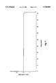
- FIG. 7 is a fluid dispensing rate graph for the system of example 1.
- the cathode chamber contains some aqueous electrolyte, which may be water, and a metal hydroxide or metal oxide.
- aqueous electrolyte which may be water
- metal hydroxide or metal oxide In general, there is a preference for metal hydroxide over metal oxide since the former is more electroactive.
- the metal hydroxide and metal oxide have general compositions M a (OH) b and M' x O y respectively, where M and M' are metallic elements with oxidation states +(b/a) and +(y*2/x).
- metal hydroxides and metal oxides include: Cu(OH) 2 , CuO, Ni(OH) 2 , NiO, Bi(OH) 3 , Bi 2 O 3 , Pb(OH) 2 , PbO, Mn(OH) 2 , MnO, Hg(OH) 2 , HgO, Cr(OH) 3 , Cr 2 O 3 , Zn(OH) 2 , ZiO, Sn(OH) 2 , and SnO.
- the overall reactions in the cell as it generates oxygen are:
- a gelling or suspension agent for example carboxymethyl cellulose and the like may be added to the electrolyte to improve manufacturability but is not otherwise required.
- the cathode material is contained in a chamber of the cell which has some portion which is electronically conductive and which may be placed in electronic communication with an electronic circuit such that upon completing the electrical circuit, the cathode is connected to the negative pole of the power source.
- a separator between the cathode material and the anode may be required.
- a separator is not required.
- An electronically conductive material such as carbon black or graphite may be added to the metal hydroxide (oxide)/electrolyte mixture.
- a separator is required regardless of the electronic conductivity of the metal hydroxide or oxide.
- the separator must be electronically insulating, ionically conductive, and moisture permeable.
- Several thin films with such characteristics are commercially available such as hydrophilic microporous membranes made of polystyrene or polyolefin.
- the anode is comprised of electronically conductive and hydrophobic materials.
- An exemplary anode consists of high surface area carbon which has been coated to some degree with a hydrophobic material such as polytetrafluoroethylene (PTFE) to make it hydrophobic.
- the coated carbon typically is pressed into a metal screen or expanded metal which serves as a current collector.
- the electronically conductive anode is in electronic communication with an electronic circuit but not in direct contact with electronically conductive material in the cathode. If the electrolyte is alkaline, an expanded metal nickel plated steel screen is very effective as an anode without carbon being present. Between the cell gas exit port(s) and the anode it is desirable to provide additional protection to prevent the loss of moisture of electrolyte as the cell generates gas.
- a film of PTFE or FEP between the gas exit port(s) and the anode is required for this purpose. If the device is to have low rate, it may be possible to utilize a sintered film which has lower moisture permeability to increase the storage stability. If the device is to have a high pump rate, then a nonsintered film which is very hydrophobic but microporous is preferred. To gain the same low moisture retention protection, a metal foil, metallized plastic film or a sintered PTFE or FEP film with adhesive may be placed over the gas port(s). An adhesive is selected such that the film will release when the cell begins to operate after activation and build up of internal pressure. The moisture barrier is very important for long shelf life since the loss of internal moisture due to evaporation will change the performance of the cell or in the extreme make the cell nonfunctionable.
- FIG. 1 shows a schematic representation of a cell.
- the cell is constructed in similar fashion to a zinc/air type button cell battery.
- the cylindrical outer can 1 serves as an anode contact and contains the cell.
- the cylindrical cap 2 is the cathode member and cathode contact and partially contains the cathode mixture. It is sometimes desirable to construct the cap or have it clad or plated with the metal which will be plating out during operation of the cell. For example if Cu(OH) 2 is the active cathode material, then it is desirable to have the cap clad or plated at least on the inside with copper or to construct the cap with metallic copper.
- the cell as it begins to generate gas, immediately causes plating onto a like metal surface whereas if the inner cap surface were stainless steel or nickel, a dissimilar metal, a delay occurs.
- This phenomenon may not be true for all potential cathode materials but is at least true for copper.
- the phenomenon is believed to occur because of disproportionation which occurs between the Cu ++ ion and metallic Cu before the cell is activated. Since it is believed that the formation of Cu + is part of the mechanism for plating, the disproportionation may set up the plating pathway before the cell is activated.
- the grommet is typically made of nylon and serves as a sealing gasket between the can and cap as well as insulator.
- the cap and can are crimped together to form a seal.
- the anode 4 is in electronic communication radially with the can, and is in ionic communication with the cathode mixture 5 which is primarily contained within the cap.
- the hydrophobic barrier typically is a PTFE or FEP film either sintered or unsintered 0.002-0.008 inches thick.
- a separator 8 electronically isolates the anode 4 from the cathode mixture 5. The separator is required if the mixture includes any electronically conductive constituents such as carbon or graphite.
- FIGS. 2A-2D schematically show several possible configurations of the anode 4.
- it may consist of a mixture of carbon and/or graphite sintered together with PTFE or FEP to form an electronically conductive film 10 which is electrochemically active and somewhat hydrophobic. This film is laminated using pressure to a nonsintered PTFE or TFE film 11.
- the anode may be similar to 2A except the films may be laminated to a metallic mesh, expanded metal or screen to serve as a current collector 12 therebetween. This configuration makes better contact radially with the can.
- the anode may consist of a mixture of carbon and/or graphite 13 which has been coated with PTFE or FEP and pressed into a metallic mesh, expanded metal or screen to serve as a current collector and laminated using pressure to a nonsintered PTFE or TFE film 11.
- the anode may be simply a metallic mesh, expanded metal or screen and co-laminated to a nonsintered PTFE or FEP film.
- FIG. 3 schematically shows the electrical circuit required to make the cell functional.
- the gas cell is referred generally as 20.
- the cell may be placed in direct contact with a direct current voltage source such as a button cell battery 21.
- a direct current voltage source such as a button cell battery 21.
- One or more batteries may be utilized.
- the rate of the device will be determined by the voltage provided by the batteries and the resistance of the resistor in the circuit.
- a convenient configuration is to affix the gas cell to the battery using an electronically conductive adhesive.
- the negative contact of the battery is in electrical communication with the gas cell cap which is in communication with the cathode.
- the circuit also includes a switch 23 and resistor 24.
- FIG. 4 shows a releasable moisture barrier 29 covering the gas outlet port(s).
- a releasable moisture barrier 29 covering the gas outlet port(s).
- the releasable moisture barrier may be metal foil with adhesive which releases under the pressure initially generated when the device is activated.
- suitable materials would include metallized plastic films, PCTFE, or sintered PTFE or FEP.
- FIG. 5 schematically shows the gas cell and battery, referred to collectively as item 30, attached to a two-chamber, bladder-type fluid dispensing reservoir.
- the bladder reservoir consists of a gas chamber outer shell 31, and a fluid chamber outer shell 32, with a flexible diaphragm 33 therebetween.
- a gas tight seal is made at the perimeter between the diaphragm and the gas chamber outer shell 31.
- a liquid tight seal is made at the perimeter of the diaphragm 33 and the fluid outer shell 32.
- fluid fills the fluid chamber 34.
- a puncture is made in the diaphragm at fluid outlet 35 and the electrical switch in the circuit (which is not shown) is completed.
- gas is generated in the gas cell, flows through the cell gas port(s) 6, and through the reservoir gas port 36.
- the diaphragm is pushed by the gas away from the gas chamber outer shell 31 to form the gas chamber.
- Simultaneously fluid flows out of fluid outlet 35 at a rate directly proportional to the rate of gas generation, which is directly proportional to the current in the circuit.
- FIG. 6 shows schematically a plunger type fluid delivery device.
- the gas cell and battery, referred together as item 30, are in a module 40 which includes the components of a multiple setting switch.
- the module is integrated to the housing 41 which is gas tight except for fluid outlet 44 and an opening for gas from the module.
- Fluid 43 is contained between the housing and the plunger 42.
- the plunger initially is tight against the upper portion of the housing near the module.
- gas from the gas cell pushes the plunger which in turn pushes the fluid out of the housing.
- a cell was constructed similar to the configurations shown in FIG. 1, FIG. 2D, and FIG. 3 and was used to drive a fluid dispensing device as shown in FIG. 5.
- the can was constructed of nickel plated steel.
- the cap was a tri-clad material of nickel, steel, and copper, wherein copper was the surface metal on the inside of the cap.
- the cathode mixture contained 30% copper hydroxide, 7.5% graphite powder, 25% sodium hydroxide, and 37.5% water.
- a Cellguard 5511 separator which is a hydrophilic microporous polyolefin membrane separator, from Hoerchst Celanese was utilized against an anode which was nickel plated steel expanded metal mesh which had been dipped in a Teflon T30 slurry and dried, then pressed to a 0.004 inch thick unsintered Teflon film from Fluorglas.
- the grommet was made of nylon 6/6.
- a hydrophobic barrier of 0.002 inch sintered Teflon film was located between the anode and the gas ports.
- the gas cell was driven with a 393 silver oxide battery from Eveready and the circuit included an 11,000 ohm resistor.
- the bladder type reservoir contained 9 cc of fluid. During operation, the rate of fluid delivery was nearly constant at the rate of 0.2 cc per day until the bladder was completely empty.
- a cathode paste of the following composition is quite useful:
- a preferred cathode paste has the following composition:
- the devices described herein work especially well in an alkaline electrolyte and generally operate optimally at a pH greater than about 8 with operation at a pH greater than about 9 being advantageous.
- FIG. 7 shows a plot of fluid dispensed over time using the device described in Example 1.
Landscapes
- Engineering & Computer Science (AREA)
- General Engineering & Computer Science (AREA)
- Mechanical Engineering (AREA)
- Manufacturing & Machinery (AREA)
- Chemical & Material Sciences (AREA)
- Chemical Kinetics & Catalysis (AREA)
- Electrochemistry (AREA)
- General Chemical & Material Sciences (AREA)
- Hybrid Cells (AREA)
Abstract
Description
M.sub.a (OH).sub.b →aM+b/2H.sub.2 O+b/4O.sub.2
M'.sub.x O.sub.y →xM'+y/2O.sub.2
______________________________________
Constituent   Range (% by wt.)
______________________________________
Cu(OH).sub.2  20-45%
Graphite       3-12%
NaOH           0-35%
Water         25-50%
______________________________________
______________________________________
Constituent   Range (% by wt.)
______________________________________
Cu(OH).sub.2  20-40%
Graphite       5-10%
NaOH          20-30%
Water         30-45%
______________________________________
______________________________________
Constituent   Range (% by wt.)
______________________________________
Cu(OH.sub.2)  28-36%
Graphite      7-9%
NaOH          22-26%
Water         33-39%
______________________________________
Claims (18)
Priority Applications (2)
| Application Number | Priority Date | Filing Date | Title |
|---|---|---|---|
| US08/685,303 US5744014A (en) | 1994-09-06 | 1996-07-23 | Storage stable electrolytic gas generator for fluid dispensing applications |
| PCT/US1997/013449 WO1999006614A1 (en) | 1996-07-23 | 1997-07-29 | Storage stable electrolytic gas generator for fluid dispensing applications |
Applications Claiming Priority (3)
| Application Number | Priority Date | Filing Date | Title |
|---|---|---|---|
| US08/300,947 US5538605A (en) | 1994-09-06 | 1994-09-06 | Solid oxide cathode-based electrochemical oxygen generator for fluid dispensing applications |
| US08/685,303 US5744014A (en) | 1994-09-06 | 1996-07-23 | Storage stable electrolytic gas generator for fluid dispensing applications |
| PCT/US1997/013449 WO1999006614A1 (en) | 1996-07-23 | 1997-07-29 | Storage stable electrolytic gas generator for fluid dispensing applications |
Related Parent Applications (1)
| Application Number | Title | Priority Date | Filing Date |
|---|---|---|---|
| US08/300,947 Continuation-In-Part US5538605A (en) | 1994-09-06 | 1994-09-06 | Solid oxide cathode-based electrochemical oxygen generator for fluid dispensing applications |
Publications (1)
| Publication Number | Publication Date |
|---|---|
| US5744014A true US5744014A (en) | 1998-04-28 |
Family
ID=26792677
Family Applications (1)
| Application Number | Title | Priority Date | Filing Date |
|---|---|---|---|
| US08/685,303 Expired - Lifetime US5744014A (en) | 1994-09-06 | 1996-07-23 | Storage stable electrolytic gas generator for fluid dispensing applications |
Country Status (2)
| Country | Link |
|---|---|
| US (1) | US5744014A (en) |
| WO (1) | WO1999006614A1 (en) |
Cited By (31)
| Publication number | Priority date | Publication date | Assignee | Title |
|---|---|---|---|---|
| US5871632A (en) * | 1996-05-14 | 1999-02-16 | Winsel; August | Controlled and regulated conveying of flowable media with a gas evolution cell and a flow multiplier |
| US5971722A (en) * | 1997-09-05 | 1999-10-26 | Baxter International Inc | Electrochemical syringe pump having a sealed storage reservoir for a charge transfer medium |
| WO2000012159A1 (en) * | 1998-09-01 | 2000-03-09 | Baxter International Inc. | Electrochemical cell module for use in liquid dispensing devices |
| US6042704A (en) * | 1995-10-06 | 2000-03-28 | Ceramatec, Inc. | Storage-stable, fluid dispensing device using a hydrogen gas generator |
| US20030068552A1 (en) * | 2001-09-17 | 2003-04-10 | Anglin David L | Alkaline cell with improved cathode |
| US20030148181A1 (en) * | 2001-09-17 | 2003-08-07 | Wang Francis P | Alkaline cell with improved cathode |
| US20030205582A1 (en) * | 2002-05-01 | 2003-11-06 | Joshi Ashok V. | Fluid delivery device having an electrochemical pump with an anionic exchange membrane and associated method |
| US20060052768A1 (en) * | 2002-05-01 | 2006-03-09 | Microlin, L.C. | Fluid delivery device having an electrochemical pump with an ion-exchange membrane and associated method |
| US20060116663A1 (en) * | 2002-05-01 | 2006-06-01 | Joshi Ashok V | Electro-osmotic fluid delivery device and method |
| US20070001024A1 (en) * | 1997-06-20 | 2007-01-04 | Microlin, L.C. | Device employing gas generating cell for facilitating controlled release of fluid into ambient environment |
| US20070021735A1 (en) * | 2005-07-15 | 2007-01-25 | Sai Bhavaraju | Dual membrane electro-osmotic fluid delivery device |
| US20070021734A1 (en) * | 2005-07-15 | 2007-01-25 | Sai Bhavaraju | Bioelectro-osmotic engine fluid delivery device |
| US20070025869A1 (en) * | 2005-07-15 | 2007-02-01 | Gordon John H | Fluid Delivery Device |
| US20070023291A1 (en) * | 2005-07-15 | 2007-02-01 | Sai Bhavaraju | Metal Trap |
| US20080102119A1 (en) * | 2006-11-01 | 2008-05-01 | Medtronic, Inc. | Osmotic pump apparatus and associated methods |
| US20080147186A1 (en) * | 2006-12-14 | 2008-06-19 | Joshi Ashok V | Electrochemical Implant For Delivering Beneficial Agents |
| US20080257915A1 (en) * | 2007-04-18 | 2008-10-23 | Truman Wold | Gas Generation Dispenser Apparatus and Method for On-Demand Fluid Delivery |
| US20080292294A1 (en) * | 2007-05-24 | 2008-11-27 | Zlotnik Arnold H | Gravity driven fluid supply vessel for dispensing an aromatic odor neutralizer |
| US20080292508A1 (en) * | 2007-05-24 | 2008-11-27 | Zlotnik Arnold H | Apparatus for dispensing an aromatic odor neutralizer |
| US7614568B2 (en) | 2000-08-24 | 2009-11-10 | Microlin, Llc | Device employing gas generating cell for facilitating controlled release of fluid into ambient environment |
| US7645540B2 (en) | 2003-08-08 | 2010-01-12 | Rovcal, Inc. | Separators for alkaline electrochemical cells |
| US7740984B2 (en) | 2004-06-04 | 2010-06-22 | Rovcal, Inc. | Alkaline cells having high capacity |
| US20100176214A1 (en) * | 2009-01-13 | 2010-07-15 | Joshi Ashok V | Greeting card fragrance delivery system |
| US20100222770A1 (en) * | 2005-07-01 | 2010-09-02 | John Howard Gordon | Fluid delivery device with a diffusion membrane for fast response time |
| US7896867B2 (en) | 2002-05-01 | 2011-03-01 | Microlin, Llc | Fluid delivery device having an electrochemical pump with an ion-exchange membrane and associated method |
| US20110311372A1 (en) * | 2010-06-17 | 2011-12-22 | Henry Hess | Pump Devices, Methods, and Systems |
| WO2014032048A1 (en) | 2012-08-24 | 2014-02-27 | Microlin, Llc. | Gas cell driven orientation independent delivery device |
| US8939435B2 (en) | 2011-06-03 | 2015-01-27 | Microlin, Llc | Device for delivery of volatile liquids to gaseous environment utilizing a gas generating cell |
| US10399102B2 (en) | 2012-08-24 | 2019-09-03 | Microlin, Llc | Spill-resistant fluid delivery device |
| US10696468B2 (en) | 2012-08-24 | 2020-06-30 | Microlin, Llc | Gas cell driven fluid delivery device for spill-resistant storage and use |
| EP3570907A4 (en) * | 2017-01-15 | 2021-02-17 | E3D Agricultural Cooperative Association Ltd. | Transfusion pump |
Families Citing this family (2)
| Publication number | Priority date | Publication date | Assignee | Title |
|---|---|---|---|---|
| US6979805B2 (en) * | 2003-01-08 | 2005-12-27 | Hewlett-Packard Development Company, L.P. | Fuel-cell resistors and methods |
| WO2010000567A1 (en) * | 2008-06-08 | 2010-01-07 | Novo Nordisk A/S | A medical delivery device |
Citations (6)
| Publication number | Priority date | Publication date | Assignee | Title |
|---|---|---|---|---|
| US5186805A (en) * | 1991-01-30 | 1993-02-16 | S. I. Scientific Innovations Ltd. | Electrolytic dispensing device |
| US5242565A (en) * | 1989-07-10 | 1993-09-07 | August Winsel | Device for electrochemical generation of gases for the transportation of fluids and similar mediums |
| US5454922A (en) * | 1993-05-07 | 1995-10-03 | Ceramatec, Inc. | Fluid dispensing pump |
| US5538605A (en) * | 1994-09-06 | 1996-07-23 | Ceramatec, Inc. | Solid oxide cathode-based electrochemical oxygen generator for fluid dispensing applications |
| US5567287A (en) * | 1993-05-07 | 1996-10-22 | Ceramatec, Inc. | Gas releasing electrochemical cell for fluid dispensing applications |
| US5593552A (en) * | 1993-05-07 | 1997-01-14 | Ceramatec, Inc. | Device for electrochemical generation of gas |
Family Cites Families (6)
| Publication number | Priority date | Publication date | Assignee | Title |
|---|---|---|---|---|
| CH557178A (en) | 1972-08-10 | 1974-12-31 | Siemens Ag | DEVICE FOR DISPENSING DRUGS. |
| US4886514A (en) | 1985-05-02 | 1989-12-12 | Ivac Corporation | Electrochemically driven drug dispenser |
| US4902278A (en) | 1987-02-18 | 1990-02-20 | Ivac Corporation | Fluid delivery micropump |
| US5423454A (en) * | 1992-08-19 | 1995-06-13 | Lippman, Deceased; Lawrence G. | Method of propellant gas generation |
| JP2942671B2 (en) | 1992-09-30 | 1999-08-30 | 富士写真フイルム株式会社 | Photosensitive material processing equipment |
| JPH0824619A (en) * | 1994-07-14 | 1996-01-30 | Japan Storage Battery Co Ltd | Liquid feeding apparatus and its preparation |
-
1996
- 1996-07-23 US US08/685,303 patent/US5744014A/en not_active Expired - Lifetime
-
1997
- 1997-07-29 WO PCT/US1997/013449 patent/WO1999006614A1/en not_active Application Discontinuation
Patent Citations (6)
| Publication number | Priority date | Publication date | Assignee | Title |
|---|---|---|---|---|
| US5242565A (en) * | 1989-07-10 | 1993-09-07 | August Winsel | Device for electrochemical generation of gases for the transportation of fluids and similar mediums |
| US5186805A (en) * | 1991-01-30 | 1993-02-16 | S. I. Scientific Innovations Ltd. | Electrolytic dispensing device |
| US5454922A (en) * | 1993-05-07 | 1995-10-03 | Ceramatec, Inc. | Fluid dispensing pump |
| US5567287A (en) * | 1993-05-07 | 1996-10-22 | Ceramatec, Inc. | Gas releasing electrochemical cell for fluid dispensing applications |
| US5593552A (en) * | 1993-05-07 | 1997-01-14 | Ceramatec, Inc. | Device for electrochemical generation of gas |
| US5538605A (en) * | 1994-09-06 | 1996-07-23 | Ceramatec, Inc. | Solid oxide cathode-based electrochemical oxygen generator for fluid dispensing applications |
Cited By (44)
| Publication number | Priority date | Publication date | Assignee | Title |
|---|---|---|---|---|
| US6042704A (en) * | 1995-10-06 | 2000-03-28 | Ceramatec, Inc. | Storage-stable, fluid dispensing device using a hydrogen gas generator |
| US5871632A (en) * | 1996-05-14 | 1999-02-16 | Winsel; August | Controlled and regulated conveying of flowable media with a gas evolution cell and a flow multiplier |
| US20070001024A1 (en) * | 1997-06-20 | 2007-01-04 | Microlin, L.C. | Device employing gas generating cell for facilitating controlled release of fluid into ambient environment |
| US5971722A (en) * | 1997-09-05 | 1999-10-26 | Baxter International Inc | Electrochemical syringe pump having a sealed storage reservoir for a charge transfer medium |
| WO2000012159A1 (en) * | 1998-09-01 | 2000-03-09 | Baxter International Inc. | Electrochemical cell module for use in liquid dispensing devices |
| US7614568B2 (en) | 2000-08-24 | 2009-11-10 | Microlin, Llc | Device employing gas generating cell for facilitating controlled release of fluid into ambient environment |
| US20030068552A1 (en) * | 2001-09-17 | 2003-04-10 | Anglin David L | Alkaline cell with improved cathode |
| US20030148181A1 (en) * | 2001-09-17 | 2003-08-07 | Wang Francis P | Alkaline cell with improved cathode |
| US6808847B2 (en) * | 2001-09-17 | 2004-10-26 | The Gillette Company | Alkaline cell with improved cathode including copper hydroxide and a sulfur additive |
| US6841302B2 (en) * | 2001-09-17 | 2005-01-11 | The Gillette Company | Alkaline cell with improved cathode |
| US7470267B2 (en) | 2002-05-01 | 2008-12-30 | Microlin, Llc | Fluid delivery device having an electrochemical pump with an anionic exchange membrane and associated method |
| US20030205582A1 (en) * | 2002-05-01 | 2003-11-06 | Joshi Ashok V. | Fluid delivery device having an electrochemical pump with an anionic exchange membrane and associated method |
| US7896867B2 (en) | 2002-05-01 | 2011-03-01 | Microlin, Llc | Fluid delivery device having an electrochemical pump with an ion-exchange membrane and associated method |
| US20060052768A1 (en) * | 2002-05-01 | 2006-03-09 | Microlin, L.C. | Fluid delivery device having an electrochemical pump with an ion-exchange membrane and associated method |
| US7458965B2 (en) | 2002-05-01 | 2008-12-02 | Microlin, Llc | Fluid delivery device having an electrochemical pump with an ion-exchange membrane and associated method |
| US20060116663A1 (en) * | 2002-05-01 | 2006-06-01 | Joshi Ashok V | Electro-osmotic fluid delivery device and method |
| US7645540B2 (en) | 2003-08-08 | 2010-01-12 | Rovcal, Inc. | Separators for alkaline electrochemical cells |
| US7763384B2 (en) | 2003-08-08 | 2010-07-27 | Rovcal, Inc. | Alkaline cells having high capacity |
| US7931981B2 (en) | 2003-08-08 | 2011-04-26 | Rovcal Inc. | Separators for alkaline electrochemical cells |
| US7740984B2 (en) | 2004-06-04 | 2010-06-22 | Rovcal, Inc. | Alkaline cells having high capacity |
| US20100222770A1 (en) * | 2005-07-01 | 2010-09-02 | John Howard Gordon | Fluid delivery device with a diffusion membrane for fast response time |
| US8348930B2 (en) | 2005-07-01 | 2013-01-08 | Microlin, Llc | Fluid delivery device with a diffusion membrane and electrochemical pump |
| US20070023291A1 (en) * | 2005-07-15 | 2007-02-01 | Sai Bhavaraju | Metal Trap |
| US20070021735A1 (en) * | 2005-07-15 | 2007-01-25 | Sai Bhavaraju | Dual membrane electro-osmotic fluid delivery device |
| US20070021734A1 (en) * | 2005-07-15 | 2007-01-25 | Sai Bhavaraju | Bioelectro-osmotic engine fluid delivery device |
| US20070025869A1 (en) * | 2005-07-15 | 2007-02-01 | Gordon John H | Fluid Delivery Device |
| US20110184389A1 (en) * | 2006-11-01 | 2011-07-28 | Medtronic, Inc. | Osmotic pump apparatus and associated methods |
| US20080102119A1 (en) * | 2006-11-01 | 2008-05-01 | Medtronic, Inc. | Osmotic pump apparatus and associated methods |
| US20080147186A1 (en) * | 2006-12-14 | 2008-06-19 | Joshi Ashok V | Electrochemical Implant For Delivering Beneficial Agents |
| US8113390B2 (en) | 2007-04-18 | 2012-02-14 | Microlin, Llc | Gas generation dispenser apparatus and method for on-demand fluid delivery |
| US20080257915A1 (en) * | 2007-04-18 | 2008-10-23 | Truman Wold | Gas Generation Dispenser Apparatus and Method for On-Demand Fluid Delivery |
| US8353426B2 (en) | 2007-04-18 | 2013-01-15 | Microlin, Llc. | Gas generation dispenser method for on-demand fluid delivery |
| US8005350B2 (en) * | 2007-05-24 | 2011-08-23 | Pestco, Inc. | Gravity driven fluid supply vessel for dispensing an aromatic odor neutralizer |
| US7857236B2 (en) | 2007-05-24 | 2010-12-28 | Pestco | Apparatus for dispensing an aromatic odor neutralizer |
| US20080292294A1 (en) * | 2007-05-24 | 2008-11-27 | Zlotnik Arnold H | Gravity driven fluid supply vessel for dispensing an aromatic odor neutralizer |
| US20080292508A1 (en) * | 2007-05-24 | 2008-11-27 | Zlotnik Arnold H | Apparatus for dispensing an aromatic odor neutralizer |
| US20100176214A1 (en) * | 2009-01-13 | 2010-07-15 | Joshi Ashok V | Greeting card fragrance delivery system |
| US20110311372A1 (en) * | 2010-06-17 | 2011-12-22 | Henry Hess | Pump Devices, Methods, and Systems |
| US8939435B2 (en) | 2011-06-03 | 2015-01-27 | Microlin, Llc | Device for delivery of volatile liquids to gaseous environment utilizing a gas generating cell |
| WO2014032048A1 (en) | 2012-08-24 | 2014-02-27 | Microlin, Llc. | Gas cell driven orientation independent delivery device |
| US9840361B2 (en) | 2012-08-24 | 2017-12-12 | Microlin, Llc | Gas cell driven orientation independent delivery device |
| US10399102B2 (en) | 2012-08-24 | 2019-09-03 | Microlin, Llc | Spill-resistant fluid delivery device |
| US10696468B2 (en) | 2012-08-24 | 2020-06-30 | Microlin, Llc | Gas cell driven fluid delivery device for spill-resistant storage and use |
| EP3570907A4 (en) * | 2017-01-15 | 2021-02-17 | E3D Agricultural Cooperative Association Ltd. | Transfusion pump |
Also Published As
| Publication number | Publication date |
|---|---|
| WO1999006614A1 (en) | 1999-02-11 |
Similar Documents
| Publication | Publication Date | Title |
|---|---|---|
| US5744014A (en) | Storage stable electrolytic gas generator for fluid dispensing applications | |
| US5567287A (en) | Gas releasing electrochemical cell for fluid dispensing applications | |
| EP0859875B1 (en) | Storage-stable, fluid dispensing device using a hydrogen gas generator | |
| US12097028B2 (en) | Drug delivery device with electrically controlled volume changing means | |
| US5593552A (en) | Device for electrochemical generation of gas | |
| US5538605A (en) | Solid oxide cathode-based electrochemical oxygen generator for fluid dispensing applications | |
| US6575961B2 (en) | Fluid delivery device and associated method | |
| WO1997013007A9 (en) | Storage-stable, fluid dispensing device using a hydrogen gas generator | |
| AU691324B2 (en) | Orally administrable delivery device | |
| AU2002309905B2 (en) | Fluid delivery device having a water generating electrochemical/chemical pump and associated method | |
| AU2002255567A1 (en) | Fluid delivery device and associated method | |
| US5968325A (en) | Auto-electrolytic hydrogen generator | |
| US5681435A (en) | Fluid dispensing pump | |
| JP2006506215A (en) | Fluid transport device having an electrochemical pump with an anion exchange membrane and associated method | |
| CA1333579C (en) | Electrochemical gas generator | |
| US8702915B2 (en) | Electrochemical gas generator and cell assembly | |
| EP1025282A1 (en) | Storage stable electrolytic gas generator for fluid dispensing applications | |
| JPH09192213A (en) | Fluid supply device |
Legal Events
| Date | Code | Title | Description |
|---|---|---|---|
| AS | Assignment |
Owner name: CERAMATEC, INC., UTAH Free format text: ASSIGNMENT OF ASSIGNORS INTEREST;ASSIGNORS:GORDON, JOHN H.;MCEVOY, JOHN;JOHSHI, ASHOK V.;REEL/FRAME:008183/0438 Effective date: 19960930 |
|
| STCF | Information on status: patent grant |
Free format text: PATENTED CASE |
|
| CC | Certificate of correction | ||
| CC | Certificate of correction | ||
| AS | Assignment |
Owner name: MICROLIN, L.C., UTAH Free format text: ASSIGNMENT OF ASSIGNORS INTEREST;ASSIGNOR:CERAMATEC, INC.;REEL/FRAME:010531/0158 Effective date: 19991221 |
|
| FPAY | Fee payment |
Year of fee payment: 4 |
|
| REMI | Maintenance fee reminder mailed | ||
| FEPP | Fee payment procedure |
Free format text: PAYOR NUMBER ASSIGNED (ORIGINAL EVENT CODE: ASPN); ENTITY STATUS OF PATENT OWNER: SMALL ENTITY |
|
| FEPP | Fee payment procedure |
Free format text: PAYER NUMBER DE-ASSIGNED (ORIGINAL EVENT CODE: RMPN); ENTITY STATUS OF PATENT OWNER: SMALL ENTITY Free format text: PAYOR NUMBER ASSIGNED (ORIGINAL EVENT CODE: ASPN); ENTITY STATUS OF PATENT OWNER: SMALL ENTITY |
|
| AS | Assignment |
Owner name: MICROLIN, LLC, UTAH Free format text: ASSIGNMENT OF ASSIGNORS INTEREST;ASSIGNOR:MICROLIN, L.C.;REEL/FRAME:016745/0438 Effective date: 20050720 |
|
| REMI | Maintenance fee reminder mailed | ||
| FPAY | Fee payment |
Year of fee payment: 8 |
|
| SULP | Surcharge for late payment |
Year of fee payment: 7 |
|
| FEPP | Fee payment procedure |
Free format text: PAT HOLDER CLAIMS SMALL ENTITY STATUS, ENTITY STATUS SET TO SMALL (ORIGINAL EVENT CODE: LTOS); ENTITY STATUS OF PATENT OWNER: SMALL ENTITY |
|
| FPAY | Fee payment |
Year of fee payment: 12 |