US5735783A - Arrangement in connection with a spreader roll drive - Google Patents
Arrangement in connection with a spreader roll drive Download PDFInfo
- Publication number
- US5735783A US5735783A US08/655,846 US65584696A US5735783A US 5735783 A US5735783 A US 5735783A US 65584696 A US65584696 A US 65584696A US 5735783 A US5735783 A US 5735783A
- Authority
- US
- United States
- Prior art keywords
- spreader roll
- arrangement
- shaft
- connection
- motor
- Prior art date
- Legal status (The legal status is an assumption and is not a legal conclusion. Google has not performed a legal analysis and makes no representation as to the accuracy of the status listed.)
- Expired - Lifetime
Links
Images
Classifications
-
- B—PERFORMING OPERATIONS; TRANSPORTING
- B65—CONVEYING; PACKING; STORING; HANDLING THIN OR FILAMENTARY MATERIAL
- B65H—HANDLING THIN OR FILAMENTARY MATERIAL, e.g. SHEETS, WEBS, CABLES
- B65H23/00—Registering, tensioning, smoothing or guiding webs
- B65H23/02—Registering, tensioning, smoothing or guiding webs transversely
- B65H23/022—Registering, tensioning, smoothing or guiding webs transversely by tentering devices
- B65H23/025—Registering, tensioning, smoothing or guiding webs transversely by tentering devices by rollers
-
- D—TEXTILES; PAPER
- D06—TREATMENT OF TEXTILES OR THE LIKE; LAUNDERING; FLEXIBLE MATERIALS NOT OTHERWISE PROVIDED FOR
- D06C—FINISHING, DRESSING, TENTERING OR STRETCHING TEXTILE FABRICS
- D06C3/00—Stretching, tentering or spreading textile fabrics; Producing elasticity in textile fabrics
- D06C3/06—Stretching, tentering or spreading textile fabrics; Producing elasticity in textile fabrics by rotary disc, roller, or like apparatus
Definitions
- the invention relates to an arrangement in connection with a spreader roll drive, the arrangement comprising supporters supporting both ends of the spreader roll, a motor for driving the spreader roll, a fixed, bent shaft on which a plurality of flexibly coupled up roll segments is rotatably arranged, and a gear with a drive for changing the angle of the fixed shaft around its centre axis.
- the driving motor rotates the roll segments around the fixed shaft to make the roll follow the arched shape of the fixed shaft.
- the construction of the spreader roll, where the roll segments rotate around a fixed shaft, has complicated the placement of the drive.
- the fixed shaft has been supported by spherical bearings, which have formed the support.
- the spherical surface has allowed rotation of the fixed shaft, causing a change in the angle between the support and the shaft.
- the actual driving motor has been connected to the support structure of the driving end so that a worm gear has been placed on the outer periphery of the spherical surface, where it has been allowed to rotate, driven by a transverse worm screw.
- a support containing a worm gear has an expensive structure.
- the driving motor is placed transversely against the fixed shaft.
- the previously known construction also includes a plurality of sliding surfaces that are quite arduous to maintain and expensive to manufacture. Adjustment of the speed of rotation of electric motors is quite advanced, and thus there is no need to use reduction gears in present drives.
- the arrangement of the invention significantly improves the construction and reduces its costs.
- the supports may be of rolling bearing type with a diameter smaller than in previous constructions.
- the locations of the supports may be more freely chosen as the driving motor is directly at the other end of the spreader roll.
- no cogwheels are needed as the drive is directly connected to the spreader roll by means of a separate clutch and an extension shaft of the motor shaft.
- the supports of the spreader roll are also essentially simplified.
- the supports comprise a metal ring with a flexible rubber ring inside for receiving the angular changes caused by the arching of the spreader roll.
- the support also operates as a spring and it will sustain the stresses it will be subjected to better than the spherical metal surfaces.
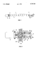
- FIG. 1 shows an arched spreader roll and an arrangement in connection with the drive.
- FIG. 2 shows the arrangement in connection with the spreader roll drive in partial cross section.
- numeral 1 denotes a spreader roll.
- Numeral 2 denotes a fixed shaft of the spreader roll.
- Numeral 3 denotes parts of a roll jacket, i.e. roll segments, arranged on the shaft 2.
- Numerals 4 and 5 denote supports of the spreader roll.
- a driving motor is denoted by numeral 6.
- the shaft 2 is rotated by a gear 7.
- a motor 6 shaft is denoted by numeral 8.
- a motor 6 flange 9 is fastened by means of screws 10 to a flange 12 in a clutch housing 11.
- a clutch 13 connects the motor 6 shaft 8 and an extension shaft 14.
- the motor 6 shaft 8 and the extension shaft 14 comprise wedges 15 or the like, by means of which they will be locked into the clutch 13.
- a bearing cap 16 is rigidly fastened at its end to the clutch housing 11.
- a bushing 17 is arranged on the extension shaft 14 and rolling bearings 18 are arranged between the bushing 17 and the bearing cap 16.
- the bearing cap 16 is arranged inside a rubber ring 19 or the like, placed inside the support 4.
- the support 4 is strengthened with a metal ring 20, fastened to a beam 21.
- the construction of the support 5 is similar to that of the support 4 and it is fastened to a beam 22.
- One end of the extension shaft 14 comprises a shoulder 23 and an enlargement 24, at the end of which an aperture 25 is arranged for the shaft 2.
- the end of the shaft 2 comprises a thinner section 26, around which a bushing 27 is arranged. Bearings 28 are arranged in the bushing 27.
- a cover 29 for the bearings 28 is fastened to the segment 3.
- the bearing 28 cover 29, the enlargement 24 of the extension shaft 14 and the segment 3 are coupled up so that they rotate around the shaft 2.
- the segment 3 and the bearing 28 cover 29 are coupled up by means of support blocks 30.
- the arrangement in connection with the spreader roll drive operates in the following way.
- the operating speed of the motor 6 is adjusted by means of a frequency transformer or the like.
- the motor 6 shaft 8 is via the clutch 13 directly connected to the extension shaft 14, which is via its enlargement 24 connected to the segment 3, farthest at the end near the motor 6. Because of the rolling bearing arrangement formed by the bearings 28, the segment 3 rotates around the shaft 20.
- An angle conforming to the thinner section 26 of the shaft 2 determines the position of the extension shaft 14 and, via the therein arranged rolling bearings 18, the position of the bearing cap 16.
- the rubber ring 19 of the support 4 yields and the bearing cap 16 is placed in a position determined by the thinner section 26 of the shaft.
- the clutch 13 housing 11 is rigidly fastened to the bearing cap 16 and the motor 6 is fastened by means of flanges 9, 12 to the clutch 13 housing 11. Because of the rubber ring 19 and the clutch 13, the coupling of the motor 6 shaft 8 is, however, not completely rigid, but shows certain flexibility.
- the extension shaft 14 may be of another type than in the above described solution, and it may be fastened to the segment in a different way than in the solution of this application.
- the bearings 18 and 28 may be realized as a different solution, and their places may be somewhat changed. Moreover, the number of bearings may be different than in the above described embodiment.
- a different type of clutch may be used in place of the clutch 13.
Abstract
Description
Claims (6)
Applications Claiming Priority (2)
| Application Number | Priority Date | Filing Date | Title |
|---|---|---|---|
| FI952727A FI100350B (en) | 1995-06-02 | 1995-06-02 | Coupling for drive device at a propagation roller |
| FI952727 | 1995-06-02 |
Publications (1)
| Publication Number | Publication Date |
|---|---|
| US5735783A true US5735783A (en) | 1998-04-07 |
Family
ID=8543530
Family Applications (1)
| Application Number | Title | Priority Date | Filing Date |
|---|---|---|---|
| US08/655,846 Expired - Lifetime US5735783A (en) | 1995-06-02 | 1996-05-31 | Arrangement in connection with a spreader roll drive |
Country Status (4)
| Country | Link |
|---|---|
| US (1) | US5735783A (en) |
| CA (1) | CA2177797C (en) |
| DE (1) | DE19621585B4 (en) |
| FI (1) | FI100350B (en) |
Cited By (9)
| Publication number | Priority date | Publication date | Assignee | Title |
|---|---|---|---|---|
| US6042525A (en) * | 1998-02-04 | 2000-03-28 | Suomen Intech Oy | Web spreader roll |
| US6306069B1 (en) * | 1997-07-07 | 2001-10-23 | Suomen Intech Oy | Spreader roll |
| US6482141B1 (en) | 2001-07-25 | 2002-11-19 | Spencer Johnston Company | Flexible end supporting arrangement for direct drive adjustable spreader rolls |
| US20040154146A1 (en) * | 2001-05-17 | 2004-08-12 | Pruitt Paul R. | Web spreader roll and methods for spreading webs of material |
| US6843762B2 (en) | 2000-12-18 | 2005-01-18 | Spencer Johnston Company | Spreader roll |
| WO2006045882A1 (en) * | 2004-10-25 | 2006-05-04 | Pikorolls Oy | Spreader roll |
| US20070137803A1 (en) * | 2003-08-23 | 2007-06-21 | Bos Gmbh & Co. Kg | Curved window roller blind for motor vehicles |
| CN102091722A (en) * | 2011-01-31 | 2011-06-15 | 中冶赛迪工程技术股份有限公司 | Roller driving method for high-speed rolling and roller device |
| CN103422200A (en) * | 2013-09-09 | 2013-12-04 | 上海淳瑞机械科技有限公司 | Feeding roller structure of rotor spinning machine |
Families Citing this family (5)
| Publication number | Priority date | Publication date | Assignee | Title |
|---|---|---|---|---|
| CA2450588C (en) * | 2003-11-25 | 2011-10-18 | Alexander D. Kanaris | Motorized drum roller with fixed ends |
| DE102004021626B3 (en) * | 2004-05-03 | 2005-12-22 | Koenig & Bauer Ag | Material web guide for rotary printing machine, has pivot bearing formed by elastically deformable section of wall of frame |
| CA2619247C (en) | 2008-02-05 | 2015-08-11 | Alexander D. Kanaris | Conveyor drive roller |
| FI125847B (en) * | 2012-05-10 | 2016-03-15 | Randax Oy | Curved roller and its operating arrangement |
| DE102022120317A1 (en) | 2022-08-11 | 2024-02-22 | Voith Patent Gmbh | Roller drive device for a roller of a machine for producing or treating a fibrous web |
Citations (13)
| Publication number | Priority date | Publication date | Assignee | Title |
|---|---|---|---|---|
| US3386149A (en) * | 1967-09-19 | 1968-06-04 | Mount Hope Machine Company Inc | Fluid bearing table roll |
| US3478555A (en) * | 1966-12-15 | 1969-11-18 | Kaufmann Tool & Eng Corp | Two-roll machine for rolling sheet metal |
| US3878883A (en) * | 1973-04-12 | 1975-04-22 | Hazelett Strip Casting Corp | Symmetrical synchronized belt-steering and tensioning system and apparatus for twin-belt continuous metal casting machines |
| US3889334A (en) * | 1972-08-01 | 1975-06-17 | Beloit Corp | Controlled deflection roll drive |
| US4006704A (en) * | 1974-08-13 | 1977-02-08 | Fmc Corporation | Straight line gluer |
| US4552201A (en) * | 1981-12-14 | 1985-11-12 | Hazelett Strip-Casting Corp. | Methods for shaping the casting region in a twin-belt continuous casting machine for improving heat transfer and product uniformity and enhanced machine performance |
| US4921037A (en) * | 1988-07-19 | 1990-05-01 | Hazelett Strip-Casting Corporation | Method and apparatus for introducing differential stresses in endless flexible metallic casting belts for enhancing belt performance in continuous metal casting machines |
| US4962577A (en) * | 1986-03-13 | 1990-10-16 | Eduard Kusters Maschinenfabrik Gmbh & Co. Kg | Work roll with improved support and lubricating system for an hydraulically supported roll |
| DE3919424A1 (en) * | 1989-06-14 | 1990-12-20 | Wittler H Gmbh & Co Kg | Curved tube section web spreading roller - has powered universal shaft connected to carrier sleeve at the axis end |
| US5174002A (en) * | 1990-10-23 | 1992-12-29 | Eduard Kusters Maschinenfabrik Gmbh & Co Kg | Deflection-controlled cylinder |
| US5421259A (en) * | 1992-09-24 | 1995-06-06 | Kabushiki Kaisha Tokyo Kikai Seisakusho | Guide roller for printing press |
| US5477912A (en) * | 1993-09-28 | 1995-12-26 | Aluminum Company Of America | Roll for use in a belt caster and an associated method |
| US5483811A (en) * | 1992-11-17 | 1996-01-16 | Allegheny Ludlum Corporation | Segmented anvil roller for refining the domain structure of electrical steels |
Family Cites Families (6)
| Publication number | Priority date | Publication date | Assignee | Title |
|---|---|---|---|---|
| US2771658A (en) * | 1953-08-03 | 1956-11-27 | Hunter James Machine Co | Roll for expanding and contracting textiles |
| BE757190A (en) * | 1969-10-21 | 1971-03-16 | Karlstad Mekaniska Ab | CYLINDER CONTROL MECHANISM |
| IT1076338B (en) * | 1977-01-27 | 1985-04-27 | Irga Ind Resine Gomma Affini S | EXPANDER CYLINDER FOR SHEET MATERIALS WITH VIBRATION DAMPING DEVICE |
| IT1083519B (en) * | 1977-06-15 | 1985-05-21 | Bassani Mariano | ROPE FABRIC OPENING SYSTEM |
| DE8907282U1 (en) * | 1989-06-14 | 1989-11-16 | H. Wittler Gmbh & Co Kg, 4815 Schloss Holte-Stukenbrock, De | |
| DE4414317A1 (en) * | 1994-04-25 | 1995-10-26 | Kleinewefers Gmbh | Guide roller for web material, in particular for paper making and finishing machines |
-
1995
- 1995-06-02 FI FI952727A patent/FI100350B/en not_active IP Right Cessation
-
1996
- 1996-05-29 DE DE19621585A patent/DE19621585B4/en not_active Expired - Lifetime
- 1996-05-30 CA CA002177797A patent/CA2177797C/en not_active Expired - Lifetime
- 1996-05-31 US US08/655,846 patent/US5735783A/en not_active Expired - Lifetime
Patent Citations (13)
| Publication number | Priority date | Publication date | Assignee | Title |
|---|---|---|---|---|
| US3478555A (en) * | 1966-12-15 | 1969-11-18 | Kaufmann Tool & Eng Corp | Two-roll machine for rolling sheet metal |
| US3386149A (en) * | 1967-09-19 | 1968-06-04 | Mount Hope Machine Company Inc | Fluid bearing table roll |
| US3889334A (en) * | 1972-08-01 | 1975-06-17 | Beloit Corp | Controlled deflection roll drive |
| US3878883A (en) * | 1973-04-12 | 1975-04-22 | Hazelett Strip Casting Corp | Symmetrical synchronized belt-steering and tensioning system and apparatus for twin-belt continuous metal casting machines |
| US4006704A (en) * | 1974-08-13 | 1977-02-08 | Fmc Corporation | Straight line gluer |
| US4552201A (en) * | 1981-12-14 | 1985-11-12 | Hazelett Strip-Casting Corp. | Methods for shaping the casting region in a twin-belt continuous casting machine for improving heat transfer and product uniformity and enhanced machine performance |
| US4962577A (en) * | 1986-03-13 | 1990-10-16 | Eduard Kusters Maschinenfabrik Gmbh & Co. Kg | Work roll with improved support and lubricating system for an hydraulically supported roll |
| US4921037A (en) * | 1988-07-19 | 1990-05-01 | Hazelett Strip-Casting Corporation | Method and apparatus for introducing differential stresses in endless flexible metallic casting belts for enhancing belt performance in continuous metal casting machines |
| DE3919424A1 (en) * | 1989-06-14 | 1990-12-20 | Wittler H Gmbh & Co Kg | Curved tube section web spreading roller - has powered universal shaft connected to carrier sleeve at the axis end |
| US5174002A (en) * | 1990-10-23 | 1992-12-29 | Eduard Kusters Maschinenfabrik Gmbh & Co Kg | Deflection-controlled cylinder |
| US5421259A (en) * | 1992-09-24 | 1995-06-06 | Kabushiki Kaisha Tokyo Kikai Seisakusho | Guide roller for printing press |
| US5483811A (en) * | 1992-11-17 | 1996-01-16 | Allegheny Ludlum Corporation | Segmented anvil roller for refining the domain structure of electrical steels |
| US5477912A (en) * | 1993-09-28 | 1995-12-26 | Aluminum Company Of America | Roll for use in a belt caster and an associated method |
Cited By (9)
| Publication number | Priority date | Publication date | Assignee | Title |
|---|---|---|---|---|
| US6306069B1 (en) * | 1997-07-07 | 2001-10-23 | Suomen Intech Oy | Spreader roll |
| US6042525A (en) * | 1998-02-04 | 2000-03-28 | Suomen Intech Oy | Web spreader roll |
| US6843762B2 (en) | 2000-12-18 | 2005-01-18 | Spencer Johnston Company | Spreader roll |
| US20040154146A1 (en) * | 2001-05-17 | 2004-08-12 | Pruitt Paul R. | Web spreader roll and methods for spreading webs of material |
| US6482141B1 (en) | 2001-07-25 | 2002-11-19 | Spencer Johnston Company | Flexible end supporting arrangement for direct drive adjustable spreader rolls |
| US20070137803A1 (en) * | 2003-08-23 | 2007-06-21 | Bos Gmbh & Co. Kg | Curved window roller blind for motor vehicles |
| WO2006045882A1 (en) * | 2004-10-25 | 2006-05-04 | Pikorolls Oy | Spreader roll |
| CN102091722A (en) * | 2011-01-31 | 2011-06-15 | 中冶赛迪工程技术股份有限公司 | Roller driving method for high-speed rolling and roller device |
| CN103422200A (en) * | 2013-09-09 | 2013-12-04 | 上海淳瑞机械科技有限公司 | Feeding roller structure of rotor spinning machine |
Also Published As
| Publication number | Publication date |
|---|---|
| CA2177797A1 (en) | 1996-12-03 |
| CA2177797C (en) | 2004-07-20 |
| FI952727A0 (en) | 1995-06-02 |
| FI952727A (en) | 1996-12-03 |
| DE19621585B4 (en) | 2005-05-04 |
| DE19621585A1 (en) | 1996-12-05 |
| FI100350B (en) | 1997-11-14 |
Similar Documents
| Publication | Publication Date | Title |
|---|---|---|
| US5735783A (en) | Arrangement in connection with a spreader roll drive | |
| US4073201A (en) | Powered wrist joint | |
| US6176804B1 (en) | Planetary gear train for a wind power station | |
| US4000979A (en) | Roll for a rolling mill | |
| KR20020095188A (en) | Bearing for an adjustable rotor blade on a wind energy plant | |
| US3997952A (en) | Roll for a rolling mill | |
| KR20010013069A (en) | Grinding machine | |
| US5937710A (en) | Harmonic-drive transmission | |
| FI56992B (en) | DRIVANORDNING FOER VALS VID PAPPERSMASKIN ELLER LIKNANDE | |
| FI103071B (en) | Bendable roll for web-like material | |
| US5174002A (en) | Deflection-controlled cylinder | |
| US4648288A (en) | Power transmitting device | |
| ATE194950T1 (en) | CYCLOID PROPELLER WITH VERTICAL SHAFT AND CONTINUOUS SELF ORIENTATION OF THE BLADES | |
| CA1192059A (en) | Drive for shell type rolls | |
| CA2124638A1 (en) | Tiltable supporting roller bearing | |
| US4480454A (en) | Skew-rolling mill for reducing solid and hollow cross-sections | |
| FI62575C (en) | MECHANICAL DRIVING ORDER FOR TORKCYLINDERGRUPP I EN PAPPERSMASKIN. | |
| CA2224221C (en) | A bearing arrangement and a coupling element of a spreading roll | |
| CA2129909A1 (en) | Swing Arm Bracket Assembly | |
| GB2203221A (en) | Deflection compensating roller assembly | |
| US5860322A (en) | Drive mechanism of a suction roll including a spur wheel gear and an outward mounting portion for a stationary suction box | |
| US3818777A (en) | Supports for large diameter drums and drive means to rotate the drums | |
| FI56888C (en) | MECHANICAL DRIVING ORDER FOR PAINT AND FAST AXEL SHAFT COVER | |
| JPH04228303A (en) | Drive for roll | |
| SU977319A1 (en) | Apparatus for centering conveyer belt |
Legal Events
| Date | Code | Title | Description |
|---|---|---|---|
| AS | Assignment |
Owner name: RAAHEN TEVO OY, FINLAND Free format text: ASSIGNMENT OF ASSIGNORS INTEREST;ASSIGNOR:JOENSUU, TEUVO;REEL/FRAME:008016/0639 Effective date: 19960517 |
|
| FEPP | Fee payment procedure |
Free format text: PAYOR NUMBER ASSIGNED (ORIGINAL EVENT CODE: ASPN); ENTITY STATUS OF PATENT OWNER: SMALL ENTITY |
|
| STCF | Information on status: patent grant |
Free format text: PATENTED CASE |
|
| FPAY | Fee payment |
Year of fee payment: 4 |
|
| FEPP | Fee payment procedure |
Free format text: PAYER NUMBER DE-ASSIGNED (ORIGINAL EVENT CODE: RMPN); ENTITY STATUS OF PATENT OWNER: SMALL ENTITY Free format text: PAYOR NUMBER ASSIGNED (ORIGINAL EVENT CODE: ASPN); ENTITY STATUS OF PATENT OWNER: SMALL ENTITY |
|
| FPAY | Fee payment |
Year of fee payment: 8 |
|
| FPAY | Fee payment |
Year of fee payment: 12 |