US5732550A - Current supply control system of electrically heated catalytic converter of internal combustion engine - Google Patents
Current supply control system of electrically heated catalytic converter of internal combustion engine Download PDFInfo
- Publication number
- US5732550A US5732550A US08/674,693 US67469396A US5732550A US 5732550 A US5732550 A US 5732550A US 67469396 A US67469396 A US 67469396A US 5732550 A US5732550 A US 5732550A
- Authority
- US
- United States
- Prior art keywords
- engine
- catalytic converter
- fuel injection
- correction factors
- heater
- Prior art date
- Legal status (The legal status is an assumption and is not a legal conclusion. Google has not performed a legal analysis and makes no representation as to the accuracy of the status listed.)
- Expired - Fee Related
Links
Images



Classifications
-
- F—MECHANICAL ENGINEERING; LIGHTING; HEATING; WEAPONS; BLASTING
- F01—MACHINES OR ENGINES IN GENERAL; ENGINE PLANTS IN GENERAL; STEAM ENGINES
- F01N—GAS-FLOW SILENCERS OR EXHAUST APPARATUS FOR MACHINES OR ENGINES IN GENERAL; GAS-FLOW SILENCERS OR EXHAUST APPARATUS FOR INTERNAL-COMBUSTION ENGINES
- F01N9/00—Electrical control of exhaust gas treating apparatus
-
- F—MECHANICAL ENGINEERING; LIGHTING; HEATING; WEAPONS; BLASTING
- F01—MACHINES OR ENGINES IN GENERAL; ENGINE PLANTS IN GENERAL; STEAM ENGINES
- F01N—GAS-FLOW SILENCERS OR EXHAUST APPARATUS FOR MACHINES OR ENGINES IN GENERAL; GAS-FLOW SILENCERS OR EXHAUST APPARATUS FOR INTERNAL-COMBUSTION ENGINES
- F01N3/00—Exhaust or silencing apparatus having means for purifying, rendering innocuous, or otherwise treating exhaust
- F01N3/08—Exhaust or silencing apparatus having means for purifying, rendering innocuous, or otherwise treating exhaust for rendering innocuous
- F01N3/10—Exhaust or silencing apparatus having means for purifying, rendering innocuous, or otherwise treating exhaust for rendering innocuous by thermal or catalytic conversion of noxious components of exhaust
- F01N3/18—Exhaust or silencing apparatus having means for purifying, rendering innocuous, or otherwise treating exhaust for rendering innocuous by thermal or catalytic conversion of noxious components of exhaust characterised by methods of operation; Control
- F01N3/20—Exhaust or silencing apparatus having means for purifying, rendering innocuous, or otherwise treating exhaust for rendering innocuous by thermal or catalytic conversion of noxious components of exhaust characterised by methods of operation; Control specially adapted for catalytic conversion
- F01N3/2006—Periodically heating or cooling catalytic reactors, e.g. at cold starting or overheating
- F01N3/2013—Periodically heating or cooling catalytic reactors, e.g. at cold starting or overheating using electric or magnetic heating means
-
- F—MECHANICAL ENGINEERING; LIGHTING; HEATING; WEAPONS; BLASTING
- F02—COMBUSTION ENGINES; HOT-GAS OR COMBUSTION-PRODUCT ENGINE PLANTS
- F02D—CONTROLLING COMBUSTION ENGINES
- F02D41/00—Electrical control of supply of combustible mixture or its constituents
- F02D41/02—Circuit arrangements for generating control signals
- F02D41/021—Introducing corrections for particular conditions exterior to the engine
- F02D41/0235—Introducing corrections for particular conditions exterior to the engine in relation with the state of the exhaust gas treating apparatus
- F02D41/024—Introducing corrections for particular conditions exterior to the engine in relation with the state of the exhaust gas treating apparatus to increase temperature of the exhaust gas treating apparatus
- F02D41/0255—Introducing corrections for particular conditions exterior to the engine in relation with the state of the exhaust gas treating apparatus to increase temperature of the exhaust gas treating apparatus to accelerate the warming-up of the exhaust gas treating apparatus at engine start
-
- F—MECHANICAL ENGINEERING; LIGHTING; HEATING; WEAPONS; BLASTING
- F02—COMBUSTION ENGINES; HOT-GAS OR COMBUSTION-PRODUCT ENGINE PLANTS
- F02D—CONTROLLING COMBUSTION ENGINES
- F02D41/00—Electrical control of supply of combustible mixture or its constituents
- F02D41/02—Circuit arrangements for generating control signals
- F02D41/14—Introducing closed-loop corrections
- F02D41/1438—Introducing closed-loop corrections using means for determining characteristics of the combustion gases; Sensors therefor
- F02D41/1444—Introducing closed-loop corrections using means for determining characteristics of the combustion gases; Sensors therefor characterised by the characteristics of the combustion gases
- F02D41/1446—Introducing closed-loop corrections using means for determining characteristics of the combustion gases; Sensors therefor characterised by the characteristics of the combustion gases the characteristics being exhaust temperatures
-
- Y—GENERAL TAGGING OF NEW TECHNOLOGICAL DEVELOPMENTS; GENERAL TAGGING OF CROSS-SECTIONAL TECHNOLOGIES SPANNING OVER SEVERAL SECTIONS OF THE IPC; TECHNICAL SUBJECTS COVERED BY FORMER USPC CROSS-REFERENCE ART COLLECTIONS [XRACs] AND DIGESTS
- Y02—TECHNOLOGIES OR APPLICATIONS FOR MITIGATION OR ADAPTATION AGAINST CLIMATE CHANGE
- Y02T—CLIMATE CHANGE MITIGATION TECHNOLOGIES RELATED TO TRANSPORTATION
- Y02T10/00—Road transport of goods or passengers
- Y02T10/10—Internal combustion engine [ICE] based vehicles
- Y02T10/12—Improving ICE efficiencies
-
- Y—GENERAL TAGGING OF NEW TECHNOLOGICAL DEVELOPMENTS; GENERAL TAGGING OF CROSS-SECTIONAL TECHNOLOGIES SPANNING OVER SEVERAL SECTIONS OF THE IPC; TECHNICAL SUBJECTS COVERED BY FORMER USPC CROSS-REFERENCE ART COLLECTIONS [XRACs] AND DIGESTS
- Y02—TECHNOLOGIES OR APPLICATIONS FOR MITIGATION OR ADAPTATION AGAINST CLIMATE CHANGE
- Y02T—CLIMATE CHANGE MITIGATION TECHNOLOGIES RELATED TO TRANSPORTATION
- Y02T10/00—Road transport of goods or passengers
- Y02T10/10—Internal combustion engine [ICE] based vehicles
- Y02T10/40—Engine management systems
Definitions
- This invention relates to a system and a method for controlling current supply of an electrically heated catalytic converter installed at the exhaust system of an internal combustion engine.
- An internal combustion engine usually has a three-way catalytic converter in the exhaust system which reduces all three types of CO, HC, and NOx emissions that escape through the exhaust system, and which removes pollutants from the exhaust gases in the engine exhaust system.
- the catalyst is ineffective or inactive until its temperature has risen to a high temperature. It takes a long time until the catalytic converter has heated up to the necessary temperature from, for example, cold engine starting. For that reason, a catalytic converter having an electric heater that heats the catalyst to promote the activation is nowadays used.
- the electrically heated catalytic converter is configured to have an electric heater in the vicinity of a carrier that carries a catalyst or to have such a carrier that is inherently manufactured as an electric heater.
- the heater is supplied with current and heats up by resistance heating. The heater thus supplied with current burns off the unburned exhaust gases generated by the engine and passing through the engine exhaust to promote the activation of the catalytic converter itself and other ordinary catalytic converter(s) installed downstream thereof.
- Japanese Laid-Open Patent Application No. 7(1995)-34,861 proposes to discontinue or inhibit the current supply to the heater of the catalytic converter, when the engine experiences misfiring, ignition timing retarding or difficulty in engine starting.
- engine operation under which an amount of unburned components in the exhaust gases is produced are not limited to the above conditions.
- cold engine starting requires a relatively great quantity of fuel injection, increasing the unburned components in the exhaust gases.
- the prior art can not cope with such engine operating conditions.
- An object of the invention is therefore to solve the drawback of the prior art and to provide a system and a method for controlling current supply of an electrically heated catalytic converter of an internal combustion engine, which inhibits the supply of current to the electrically heated catalytic converter under the engine operating conditions in which the quantity of fuel injection is relatively great such that the ambient temperature of the engine exhaust system is increased, thereby preventing the catalytic converter from being damaged or shortened in service life.
- the present invention provides a system for controlling current supply to an electrically heated catalytic converter of an internal combustion engine, comprising a catalytic converter installed in an exhaust system of the engine for reducing pollutants from exhaust gases emitted from the engine, the catalytic converter having a heater, a power source, current supplying means for connecting the power source to the heater of the catalytic converter to supply current thereto, fuel injection quantity determining means for determining a basic quantity of fuel injection, correction factor determining means for determining correction factors for correcting the basic quantity of fuel injection, output fuel injection quantity determining means for determining an output quantity of fuel injection to be supplied to the engine based on the basic quantity of fuel injection and the correction factors, discriminating means for discriminating whether at least one of the correction factors is greater than a predetermined value, and current supply inhibiting means for inhibiting the current supply to the heater of the catalytic converter when said at least one of the correction factors is greater than the predetermined value.
- FIG. 1 is an overall schematic view showing a current supply control system of an electrically heated catalytic converter installed at the exhaust system of an internal combustion engine according to the invention as well as the fuel metering control system of the engine;
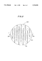
- FIG. 2 is an explanatory plan view of a carrier that carries the catalyst of the catalytic converter illustrated in FIG. 1;
- FIG. 3 is a flowchart showing the operation of the fuel metering control system illustrated in FIG. 1;
- FIG. 4 is a flowchart showing the operation of the current supply control system according to the invention to determine whether the bit of a flag indicative of the current supply is to be inhibited or not;
- FIG. 5 is a flowchart showing the current supply control of the electrically heated catalytic converter illustrated in FIG. 1 using the flag whose bit is determined in the flowchart of FIG. 4;
- FIG. 6 is a graph showing the characteristics of the time TON during which current is supplied to the catalytic converter heater, determined with respect to the exhaust system ambient temperature Tcat and referred to in the flowchart of FIG. 5;
- FIG. 7 is a graph showing the characteristics of the time TON during which current is supplied to the catalytic converter heater, determined with respect to the intake air temperature TA and referred to in the flowchart of FIG. 5;
- FIG. 8 is a graph showing the characteristics of the time TON during which current is supplied to the catalytic converter heater, determined with respect to the engine coolant temperature TW and referred to in the flowchart of FIG. 5;
- FIG. 9 is a graph showing the characteristics of the voltage VEHC to be applied to the catalytic converter heater, determined with respect to the exhaust system ambient temperature Tcat and referred to in the flowchart of FIG. 5;
- FIG. 10 is a graph showing the characteristics of the voltage VEHC to be applied to the catalytic converter heater, determined with respect to the intake air temperature TA and referred to in the flowchart of FIG. 5;
- FIG. 11 is a graph showing the characteristics of the voltage VEHC to be applied to the catalytic converter heater, determined with respect to the engine coolant temperature TW and referred to in the flowchart of FIG. 5;
- FIG. 12 is a flowchart, similar to FIG. 4, but showing the operation of the system according to a second embodiment of the invention.
- FIG. 13 is a flowchart, similar to FIG. 4, but showing the operation of the system according to a third embodiment of the invention.
- FIG. 1 is an overall schematic view showing a current supply control system of an electrically heated catalytic converter installed at the exhaust system of an internal combustion engine according to the invention, as well as the fuel metering control system of the engine.
- Reference numeral 10 in this figure designates a multicylinder engine such as a four-cylinder internal combustion engine.
- Air drawn into an air intake pipe 12 through an air cleaner (not shown) mounted on a far end thereof is supplied to each of the first to fourth cylinders through a surge tank and an intake manifold (neither shown), while the flow thereof is adjusted by a throttle valve 14 provided in the air intake pipe 12.
- a fuel injector 16 for injecting fuel is installed in the vicinity of intake valves (not shown) of each cylinder of the engine.
- the injected fuel mixes with the intake air to form an air-fuel mixture that is ignited in the associated cylinder by a spark plug (not shown).
- the resulting combustion of the air-fuel mixture drives a piston (not shown) down.
- the engine is cranked by a cranking motor 17 (starter) at the time of starting.
- the exhaust gas produced by the combustion is discharged through exhaust valves and an exhaust manifold (neither shown) to an exhaust pipe 18.
- the exhaust pipe 18 is installed with, in order from the upstream side (in terms of exhaust gas flow), the aforesaid electrically heated catalytic converter (hereinafter referred to as "EHC") 20 having a heater (not expressly shown), a start catalytic converter 22 and a three-way catalytic converter 24, which burn off the remaining HC, CO, and NOx emissions in the exhaust gases which escape from the cylinders thus reducing pollutants in the exhaust gases from the engine exhaust system.
- the start catalytic converter 22 (known as a "light-off catalyst”) is configured to have a relatively small diameter and volume and is provided in particular for enhancing catalyst conversion efficiency immediately after engine starting.
- the body of the EHC 20, i.e., a carrier that carries the catalyst, is made of a metal mesh.
- the metal mesh is manufactured by extruding metallic materials, then by sintering them to a ceramic bar, and then by cutting the bar into disc-shaped slices of 10 cm thickness.
- the metal mesh 200 is provided with slits 202 for a current supply path 204 therebetween.
- the current path has an anode 206 and a cathode 208 at opposite ends thereof.
- an alternator 26 is provided in the vicinity of the engine 10.
- the alternator 26 is connected to the crankshaft (not shown) of the engine 10 and is driven to produce electric power.
- the generated electric energy is supplied to the EHC 20 or a battery 28.
- a switch 30 is inserted in the current supply circuit.
- terminals 30a and 30b are connected, the anode of the metal mesh (heater) of the EHC 20 is connected with the alternator 26 to be supplied with current for heating up.
- the heated EHC 20 burns off the remaining emissions generated immediately after the engine starting.
- the EHC 20 further heats up with the heat generated by the chemical reaction of the burning and promptly reaches the activation temperature, thereby promoting the start catalytic converter 22 and the three-way catalytic converter 24 installed downstream thereof to activate.
- the exhaust pipe 18 is connected with a conduit 32 which has an air pump 34 at the opposite end for supplying secondary air. Since a large amount of unburned gases are produced at engine starting, the air pump 34 is installed to supply air to the exhaust pipe 18 to promote burning, thereby enhancing conversion efficiency of the catalysts.
- a crankshaft position sensor 36 illustrated as “NE” in the figure, is provided on the camshaft or crankshaft (neither shown) which produces a signal once per predetermined crank angular position.
- a camshaft position sensor 38 illustrated as “CYL” in the figure, is similarly provided on the camshaft (not shown) which produces a signal at a prescribed crank angular position of the first cylinder.
- a throttle position sensor 40 illustrated as “ ⁇ TH” in the figure, is connected to the throttle valve 14 to detect, and to generate a signal indicative of, the degree of opening of the throttle valve 14.
- the air intake pipe 12 is branched off downstream of the position where the throttle valve 14 is placed, to have a branch 42.
- a manifold absolute pressure sensor 44 illustrated as "PBA" in the figure, is installed at the far end of the branch 42, to detect, and to generate a signal indicative of, the intake manifold pressure downstream of the throttle valve 14 in terms of absolute pressure.
- the air intake pipe 12 is provided with an intake air temperature sensor 46, illustrated as “TA” in the figure, for detecting, and for generating a signal indicative of, the temperature of the intake air; and an engine coolant temperature sensor 48, illustrated as "TW” in the figure, for detecting, and for generating a signal indicative of, the temperature of the engine coolant is provided at a suitable location on the engine 10.
- TA intake air temperature sensor
- TW engine coolant temperature sensor
- the exhaust pipe 18 is provided with, upstream of the intersection where the conduit 32 is connected, a first oxygen sensor 50 comprising an O 2 sensor for detecting, and for generating a signal indicative of, the oxygen content in the exhaust gases.
- the exhaust pipe 18 is further provided with a second oxygen sensor 52 similarly comprising an O 2 sensor, at a position between the start catalytic converter 22 and the three-way catalytic converter 24.
- a temperature sensor 53 illustrated as "Tcat" in the figure, is provided in the proximity of the second O 2 sensor 52 to detect, and for generating a signal indicative of, the exhaust system ambient temperature.
- the first and second O 2 sensors are respectively provided with a heater which heats up a detection element comprised of a special ceramic core, upon receipt of current from current supply circuits (neither shown). Since the structure and configuration of the O 2 sensors of this kind are known from prior art references such as Japanese Laid-Open Patent Application Nos. Hei 1(1989)-232,246 and Hei 2(1990)-24,550, no further explanation thereof will be made.
- the signals outputted from the sensors are sent to a control unit 54 that is illustrated as "ECU" in the figure.
- the ECU 54 comprises a microcomputer made up of an input circuit 54a, a CPU 54b, a memory 54c and an output circuit 54d.
- the input circuit 54a carries out various procedures including shaping some sensor signal waveforms, converting some sensor signals to predetermined levels in voltage, and converting some analog sensor signals into digital values.
- the memory 54c stores various data including calculation programs and the results of the calculations in response to the instructions made by the CPU 54b.
- the CPU 54b operates, via the switch 30, to connect the alternator 26 to the EHC 20 to supply current thereto in response to the detected parameters.
- the alternator 26 has a regulator 56.
- the CPU 54b determines and outputs a pulse train indicative of a duty cycle in a pulse-width modulation control such that the alternator 26 produces the electric power at a level determined by the duty cycle.
- the alternator 26 is connected with the battery 28 to charge it.
- the battery 28 is connected, through a line 60, to various electric loads including an electric motor (not shown) of the air pump 34.
- the CPU 54b controls the operation of the air pump 34 by controlling the operation of the motor, and controls fuel metering through the fuel injector 16. More specifically, the CPU 54b determines the amount of fuel injection (the amount of fuel supply) in terms of time and controls the fuel injector 16 to open for the determined time.
- FIG. 3 is a flowchart illustrating the fuel metering control just mentioned.
- the program begins at S10 in which a basic quantity of fuel injection Tim is determined by retrieving mapped data stored in the memory 54c using the detected engine speed NE and the manifold pressure PBA indicative of the engine load.
- the program then proceeds to S12 in which various correction factors obtained as multiplication terms and generally named as KTOTAL are calculated (explained later), to S14 in which a similar correction factor obtained as a sum of addition terms including a correction factor due to atmospheric pressure is calculated, to S16 in which an output quantity of fuel injection Tout is calculated in the manner shown there as the opening period of the fuel injector 16, and to S18 in which the calculated output quantity of fuel injection Tout is outputted, as a command, to a driver circuit (not shown) of the fuel injector 16. The dead time of the fuel injector 16 is added the command.
- the correction factors KTOTAL obtained as multiplication terms are classified into two groups.
- the first group includes the correction factors for increasing the basic quantity of fuel injection at engine warming up and the second group includes the correction factors other than those for engine warmup enrichment.
- the correction factors for increasing the basic quantity of fuel injection include the following:
- KTW a correction factor due to the engine coolant temperature
- KTA a correction factor due to the intake air temperature
- KCR a correction factor due to engine cranking
- the correction factors falling in the second group i.e., the correction factors other than KWU, include:
- the program starts at S20 in which it is checked whether the engine warmup enrichment correction factor KWU is greater than a predetermined value Kref (for example 2.0). When it is found in S20 that the factor KWU exceeds the predetermined value Kref, the program proceeds to S22 in which the bit of a flag FEHC is reset to zero. On the other hand, when S20 finds that KWU does not exceed Kref, the program goes to S24 in which the bit of the flag is set to 1. As will be explained later, resetting the flag bit to zero means that current supply is inhibited.
- Kref for example 2.0
- the engine warmup enrichment correction factor KWU exceeds the predetermined value Kref, in other words, when the quantity of fuel injection is relatively large, the current supply to the heater of the EHC 20 is inhibited or not performed. With the arrangement, the EHC heater does not heat up.
- the EHC heater If the EHC heater is supplied with current and heats up, the heated EHC will burn off the unburned emissions produced by the engine and will further heat up with the heat generated by the chemical reaction of the burning. Since the quantity of fuel injection is increased in engine warmup so that the amount of unburned emissions is increased, the ambient temperature rises excessively. As a result, the metal mesh 200 of the EHC 20, and/or the start catalytic converter 22 and the three-way catalytic converter 24, are exposed in the high temperature, rendering them vulnerable to degradation or damaged.
- the predetermined value Kref should therefore be determined, from the reverse of the above, as sufficient for discriminating the engine operation in which the exhaust system ambient temperature rises so high that the EHC 20, etc., are liable to be degraded or damaged.
- the program then proceeds to S106 in which various engine operating parameters including the engine speed NE, the intake air temperature TA, the engine coolant temperature TW, and the exhaust system ambient temperature Tcat are read, and to S108 in which the time TON during which the current is to be supplied to the EHC 20 and the voltage VEHC to be applied to the EHC 20 are determined.
- the voltage VEHC is determined to be, for example, 30 V at cold engine starting.
- the current supply time TON is determined, as illustrated in FIGS. 6 to 8, such that it decreases with increasing exhaust system ambient temperature Tcat, with increasing intake air temperature TA, or with increasing engine coolant temperature TW.
- the voltage VEHC is also determined to be less as these temperatures rise.
- the program then proceeds to S110 in which it is again checked whether the engine speed NE has reached a reference engine speed NEK (e.g. 400 rpm) indicating that the engine runs by itself without the aid of the cranking motor 17. If the result is affirmative, the program goes to S112 and to S116 via S114 in which it is respectively determined whether the exhaust system ambient temperature Tcat, the intake air temperature TA and the engine coolant temperature TW are within a range defined between values A and B, C and D or E and F, respectively.
- a reference engine speed NEK e.g. 400 rpm
- the program proceeds to S118 in which the alternator 26 is switched to be connected with the EHC 20 (via the terminals 30a, 30b) and the alternator 26 is controlled, through the regulator 56, to generate the determined voltage VEHC and apply the voltage to the heater of the EHC 20 to produce the current that passes through the EHC heater.
- the program then advances to S120 in which the time is measured and when it has reached the time TON, the terminal 30a is switched to connect with the other terminal 30c to open the circuit and discontinue the current supply to the EHC heater.
- the system is configured such that when the quantity of fuel injection is relatively great in the engine operation including engine warmup or engine starting, the current supply to the EHC 20 is inhibited or not performed. With the arrangement, it becomes possible to prevent the exhaust system ambient temperature from rising so high that the metal mesh 200 carrying the catalyst and/or the start catalytic converter 22 and the three-way catalytic converter 24 are degraded or damaged by the high temperature, preventing them from being degraded or damaged earlier.
- FIG. 12 is a flowchart, similar to FIG. 4, but showing the operation of the system according to a second embodiment of the invention.
- the program starts at S200 in which it is checked whether a cranking time TCR during which the engine was in cranking is greater than a predetermined time Tref.
- the time TCR is obtained by measuring the time during which the engine speed NE is at or below the aforesaid reference engine speed NEK indicating that the engine runs by itself without the aid of the cranking motor 17.
- the time TCR is determined by measuring the time during which the cranking motor 17 is operative.
- the program goes to S202 in which the bit of the flag FEHC is reset to zero indicating that the current supply to the heater of the EHC 20 is inhibited.
- the program goes to S204 in which the bit of the flag FEHC is set to 1 indicating the current supply to the EHC heater is to be performed.
- the predetermined time Tref should be determined in a similar manner as the predetermined value Kref such that it is sufficient for discriminating the engine operation in which the exhaust system ambient temperature rises so high that the EHC 20, etc., are degraded or damaged.
- FIG. 13 is a flowchart, similar to FIG. 4, but showing the operation of the system according to a third embodiment of the invention.
- the program starts at S300 in which it is checked whether the engine warmup enrichment correction factor KWU is greater than the predetermined value Kref and if it is affirmative, the program goes to S302 in which the bit of the flag is reset to zero. If the result is negative, on the other hand, the program goes to S304 in which it is checked whether the engine cranking time TCR is greater than the predetermined time Tref, and if it is, the program goes to S302. If not, however, the program goes to S306 in which the bit of the flag FEHC is set to 1 indicating that the current supply to the EHC heater should be made.
- the EHC has been explained as being manufactured through extrusion, the EHC should not be limited to this type. Instead, it is alternatively possible to manufacture it in the shape of the so-called metal-wheel type, by winding a metal ribbon spirally.
Landscapes
- Engineering & Computer Science (AREA)
- Chemical & Material Sciences (AREA)
- Combustion & Propulsion (AREA)
- Mechanical Engineering (AREA)
- General Engineering & Computer Science (AREA)
- Chemical Kinetics & Catalysis (AREA)
- Health & Medical Sciences (AREA)
- Toxicology (AREA)
- Exhaust Gas After Treatment (AREA)
- Electrical Control Of Air Or Fuel Supplied To Internal-Combustion Engine (AREA)
Applications Claiming Priority (2)
| Application Number | Priority Date | Filing Date | Title |
|---|---|---|---|
| JP19124495A JP3602613B2 (ja) | 1995-07-04 | 1995-07-04 | 内燃機関の排気ガス浄化装置 |
| JP7-191244 | 1995-07-04 |
Publications (1)
| Publication Number | Publication Date |
|---|---|
| US5732550A true US5732550A (en) | 1998-03-31 |
Family
ID=16271304
Family Applications (1)
| Application Number | Title | Priority Date | Filing Date |
|---|---|---|---|
| US08/674,693 Expired - Fee Related US5732550A (en) | 1995-07-04 | 1996-07-02 | Current supply control system of electrically heated catalytic converter of internal combustion engine |
Country Status (2)
| Country | Link |
|---|---|
| US (1) | US5732550A (ja) |
| JP (1) | JP3602613B2 (ja) |
Cited By (13)
| Publication number | Priority date | Publication date | Assignee | Title |
|---|---|---|---|---|
| WO2001022073A1 (de) * | 1999-09-17 | 2001-03-29 | Robert Bosch Gmbh | Abgassensor zum zünden einer exothermen reaktion |
| US6269631B1 (en) * | 1996-07-01 | 2001-08-07 | Fraunhofer-Gesellschaft Zur Forderung Der Angewandten Forschung E.V. | Process and device for operating an internal combustion engine with less pollutant emission |
| US6381955B1 (en) * | 2001-02-07 | 2002-05-07 | Visteon Global Technologies, Inc. | Method and system for providing electricity from an integrated starter-alternator to an electrically heated catalyst |
| US20100192549A1 (en) * | 2009-02-04 | 2010-08-05 | Gm Global Technology Operations, Inc. | Method and system for controlling an electrically heated particulate filter |
| US20100319315A1 (en) * | 2009-06-17 | 2010-12-23 | Gm Global Technology Operations, Inc. | Detecting particulate matter load density within a particulate filter |
| US20110000194A1 (en) * | 2009-07-02 | 2011-01-06 | Gm Global Technology Operations, Inc. | Selective catalytic reduction system using electrically heated catalyst |
| US20110000195A1 (en) * | 2009-07-02 | 2011-01-06 | Gm Global Technology Operations, Inc. | Reduced volume electrically heated particulate filter |
| US20110036076A1 (en) * | 2009-08-12 | 2011-02-17 | Gm Global Technology Operations, Inc. | Systems and methods for layered regeneration of a particulate matter filter |
| US20110113763A1 (en) * | 2008-06-13 | 2011-05-19 | Toyota Jidosha Kabushiki Kaisha | Exhaust gas purification apparatus of an internal combustion engine |
| CN107923289A (zh) * | 2015-06-12 | 2018-04-17 | Bae系统控制有限公司 | 用于减少来自内燃机的排放的方法和系统 |
| EP3375994A1 (en) * | 2017-03-17 | 2018-09-19 | Volvo Car Corporation | Method for preconditioning a vehicle before engine start and a vehicle adapted to be preconditioned before engine start |
| US20180274469A1 (en) * | 2017-03-27 | 2018-09-27 | Ford Global Technologies, Llc | Methods and systems for an exhaust oxygen sensor operation |
| GB2605876A (en) * | 2021-03-02 | 2022-10-19 | Cummins Emission Solutions Inc | Aftertreatment system with gas sensor downstream of a heater |
Families Citing this family (2)
| Publication number | Priority date | Publication date | Assignee | Title |
|---|---|---|---|---|
| WO2005073528A1 (ja) * | 2004-02-02 | 2005-08-11 | Nissan Diesel Motor Co., Ltd. | エンジンの排気浄化装置 |
| JP5975069B2 (ja) * | 2014-07-01 | 2016-08-23 | トヨタ自動車株式会社 | 内燃機関の制御装置 |
Citations (8)
| Publication number | Priority date | Publication date | Assignee | Title |
|---|---|---|---|---|
| JPH01232246A (ja) * | 1988-03-10 | 1989-09-18 | Mazda Motor Corp | 半導体排気ガスセンサー |
| JPH0224550A (ja) * | 1988-07-13 | 1990-01-26 | Toyota Motor Corp | ヒータ付き酸素濃度センサのヒータ電力制御装置 |
| US5261230A (en) * | 1991-08-02 | 1993-11-16 | Toyota Jidosha Kabushiki Kaisha | Device for controlling heating of catalyst for purifying exhaust gas |
| JPH0734861A (ja) * | 1993-07-15 | 1995-02-03 | Mazda Motor Corp | エンジンの排気浄化装置 |
| US5428955A (en) * | 1991-08-02 | 1995-07-04 | Toyota Jidosha Kabushiki Kaisha | Device for controlling heating of catalyst for purifying exhaust gas |
| US5459999A (en) * | 1993-07-05 | 1995-10-24 | Mitsubishi Denki Kabushiki Kaisha | Exhaust gas cleaner system for an internal combustion engine with catalytic converter supplied with secondary air |
| US5537321A (en) * | 1992-10-15 | 1996-07-16 | Toyota Jidosha Kabushiki Kaisha | Diagnostic apparatus for controlling the operation of a catalytic converter |
| US5553451A (en) * | 1994-05-30 | 1996-09-10 | Toyota Jidosha Kabushiki Kaisha | Electrically heated catalytic converter system for an engine |
-
1995
- 1995-07-04 JP JP19124495A patent/JP3602613B2/ja not_active Expired - Fee Related
-
1996
- 1996-07-02 US US08/674,693 patent/US5732550A/en not_active Expired - Fee Related
Patent Citations (9)
| Publication number | Priority date | Publication date | Assignee | Title |
|---|---|---|---|---|
| JPH01232246A (ja) * | 1988-03-10 | 1989-09-18 | Mazda Motor Corp | 半導体排気ガスセンサー |
| JPH0224550A (ja) * | 1988-07-13 | 1990-01-26 | Toyota Motor Corp | ヒータ付き酸素濃度センサのヒータ電力制御装置 |
| US5261230A (en) * | 1991-08-02 | 1993-11-16 | Toyota Jidosha Kabushiki Kaisha | Device for controlling heating of catalyst for purifying exhaust gas |
| US5428955A (en) * | 1991-08-02 | 1995-07-04 | Toyota Jidosha Kabushiki Kaisha | Device for controlling heating of catalyst for purifying exhaust gas |
| US5537321A (en) * | 1992-10-15 | 1996-07-16 | Toyota Jidosha Kabushiki Kaisha | Diagnostic apparatus for controlling the operation of a catalytic converter |
| US5459999A (en) * | 1993-07-05 | 1995-10-24 | Mitsubishi Denki Kabushiki Kaisha | Exhaust gas cleaner system for an internal combustion engine with catalytic converter supplied with secondary air |
| US5560202A (en) * | 1993-07-05 | 1996-10-01 | Mitsubishi Denki Kabushiki Kaisha | Exhaust gas cleaner system for an internal combustion engine with catalytic converter supplied with secondary air |
| JPH0734861A (ja) * | 1993-07-15 | 1995-02-03 | Mazda Motor Corp | エンジンの排気浄化装置 |
| US5553451A (en) * | 1994-05-30 | 1996-09-10 | Toyota Jidosha Kabushiki Kaisha | Electrically heated catalytic converter system for an engine |
Cited By (26)
| Publication number | Priority date | Publication date | Assignee | Title |
|---|---|---|---|---|
| US6269631B1 (en) * | 1996-07-01 | 2001-08-07 | Fraunhofer-Gesellschaft Zur Forderung Der Angewandten Forschung E.V. | Process and device for operating an internal combustion engine with less pollutant emission |
| WO2001022073A1 (de) * | 1999-09-17 | 2001-03-29 | Robert Bosch Gmbh | Abgassensor zum zünden einer exothermen reaktion |
| US6381955B1 (en) * | 2001-02-07 | 2002-05-07 | Visteon Global Technologies, Inc. | Method and system for providing electricity from an integrated starter-alternator to an electrically heated catalyst |
| US20110113763A1 (en) * | 2008-06-13 | 2011-05-19 | Toyota Jidosha Kabushiki Kaisha | Exhaust gas purification apparatus of an internal combustion engine |
| US20100192549A1 (en) * | 2009-02-04 | 2010-08-05 | Gm Global Technology Operations, Inc. | Method and system for controlling an electrically heated particulate filter |
| US8584445B2 (en) | 2009-02-04 | 2013-11-19 | GM Global Technology Operations LLC | Method and system for controlling an electrically heated particulate filter |
| US20100319315A1 (en) * | 2009-06-17 | 2010-12-23 | Gm Global Technology Operations, Inc. | Detecting particulate matter load density within a particulate filter |
| US8950177B2 (en) | 2009-06-17 | 2015-02-10 | GM Global Technology Operations LLC | Detecting particulate matter load density within a particulate filter |
| US20110000195A1 (en) * | 2009-07-02 | 2011-01-06 | Gm Global Technology Operations, Inc. | Reduced volume electrically heated particulate filter |
| US8443590B2 (en) | 2009-07-02 | 2013-05-21 | GM Global Technology Operations LLC | Reduced volume electrically heated particulate filter |
| US8479496B2 (en) | 2009-07-02 | 2013-07-09 | GM Global Technology Operations LLC | Selective catalytic reduction system using electrically heated catalyst |
| US20110000194A1 (en) * | 2009-07-02 | 2011-01-06 | Gm Global Technology Operations, Inc. | Selective catalytic reduction system using electrically heated catalyst |
| US8511069B2 (en) * | 2009-08-12 | 2013-08-20 | GM Global Technology Operations LLC | Systems and methods for layered regeneration of a particulate matter filter |
| US20110036076A1 (en) * | 2009-08-12 | 2011-02-17 | Gm Global Technology Operations, Inc. | Systems and methods for layered regeneration of a particulate matter filter |
| US10876457B2 (en) | 2015-06-12 | 2020-12-29 | Bae Systems Controls Inc. | Method and system for reducing emissions from an internal combustion engine |
| EP3307998A4 (en) * | 2015-06-12 | 2019-03-06 | BAE Systems Controls Inc. | METHOD AND SYSTEM FOR REDUCING EMISSIONS FROM A COMBUSTION ENGINE |
| CN107923289B (zh) * | 2015-06-12 | 2020-08-07 | Bae系统控制有限公司 | 用于减少来自内燃机的排放的方法和系统 |
| CN107923289A (zh) * | 2015-06-12 | 2018-04-17 | Bae系统控制有限公司 | 用于减少来自内燃机的排放的方法和系统 |
| US11300033B2 (en) | 2015-06-12 | 2022-04-12 | Bae Systems Controls Inc. | Method and system for a hybrid vehicle |
| EP3375994A1 (en) * | 2017-03-17 | 2018-09-19 | Volvo Car Corporation | Method for preconditioning a vehicle before engine start and a vehicle adapted to be preconditioned before engine start |
| CN108625946A (zh) * | 2017-03-17 | 2018-10-09 | 沃尔沃汽车公司 | 启动之前预处理车辆的方法和适于启动之前预处理的车辆 |
| US20180274469A1 (en) * | 2017-03-27 | 2018-09-27 | Ford Global Technologies, Llc | Methods and systems for an exhaust oxygen sensor operation |
| US10422292B2 (en) * | 2017-03-27 | 2019-09-24 | Ford Global Technologies, Llc | Methods and systems for an exhaust oxygen sensor operation |
| GB2605876A (en) * | 2021-03-02 | 2022-10-19 | Cummins Emission Solutions Inc | Aftertreatment system with gas sensor downstream of a heater |
| US11591949B2 (en) | 2021-03-02 | 2023-02-28 | Cummins Emission Solutions Inc. | Aftertreatment system with gas sensor downstream of a heater |
| GB2605876B (en) * | 2021-03-02 | 2023-04-12 | Cummins Emission Solutions Inc | Aftertreatment system with gas sensor downstream of a heater |
Also Published As
| Publication number | Publication date |
|---|---|
| JPH0921310A (ja) | 1997-01-21 |
| JP3602613B2 (ja) | 2004-12-15 |
Similar Documents
| Publication | Publication Date | Title |
|---|---|---|
| US5740675A (en) | Exhaust system ambient temperature detection system for internal combustion engine | |
| US5758492A (en) | Failure detection system of electrically heated catalytic converter of internal combustion engine | |
| US5782086A (en) | Failure detection system of exhaust secondary air supply system of internal combustion engine | |
| EP1380732B1 (en) | Method and apparatus for desulphating a NOx trap | |
| US6340014B1 (en) | Control for direct fuel injection spark ignition internal combustion engine | |
| EP0826869B1 (en) | Exhaust gas heating system for in-cylinder injection internal combustion engine | |
| US5732550A (en) | Current supply control system of electrically heated catalytic converter of internal combustion engine | |
| US5852929A (en) | Failure detection system of exhaust secondary air supply system of internal combustion engine | |
| US5784878A (en) | Idle speed control system of internal combustion engine | |
| US6205776B1 (en) | Air-fuel ration control system for multi-cylinder internal combustion engine | |
| US5501073A (en) | Ignition timing control system for internal combustion engines | |
| US11274590B2 (en) | System and method for exhaust gas aftertreatment of an internal combustion engine | |
| US5353775A (en) | Air-fuel ratio control system for internal combustion engine | |
| US6345500B2 (en) | Cylinder direct injection spark-ignition internal combustion engine | |
| EP2218891B1 (en) | Temperature Control Device for Catalyst | |
| US5385017A (en) | Apparatus for controlling heating of a catalytic converter of an internal combustion engine | |
| US5129228A (en) | Electronic engine control system | |
| US6050086A (en) | Exhaust emission control apparatus for internal combustion engine | |
| US5689952A (en) | Exhaust gas-purifying system for internal combustion engines | |
| US5806307A (en) | Exhaust gas-purifying system for internal combustion engines | |
| US5493857A (en) | Exhaust gas-purifying system for internal combustion engines | |
| KR0147747B1 (ko) | 내연기관용 공연비 제어 시스템 | |
| JP3550215B2 (ja) | 内燃エンジンの排気ガス浄化装置 | |
| US5819531A (en) | Control device for electrically-heated catalyzers | |
| US5600949A (en) | Exhaust gas-purifying system for internal combustion engines |
Legal Events
| Date | Code | Title | Description |
|---|---|---|---|
| AS | Assignment |
Owner name: HONDA GIKEN KOGYO KABUSHIKI KAISHA, JAPAN Free format text: ASSIGNMENT OF ASSIGNORS INTEREST;ASSIGNORS:MURAMATSU, HIROAKI;SHIMASAKI, YUICHI;AOKI, TAKUYA;AND OTHERS;REEL/FRAME:008170/0837 Effective date: 19960902 |
|
| FEPP | Fee payment procedure |
Free format text: PAYOR NUMBER ASSIGNED (ORIGINAL EVENT CODE: ASPN); ENTITY STATUS OF PATENT OWNER: LARGE ENTITY |
|
| FPAY | Fee payment |
Year of fee payment: 4 |
|
| REMI | Maintenance fee reminder mailed | ||
| LAPS | Lapse for failure to pay maintenance fees | ||
| STCH | Information on status: patent discontinuation |
Free format text: PATENT EXPIRED DUE TO NONPAYMENT OF MAINTENANCE FEES UNDER 37 CFR 1.362 |
|
| FP | Lapsed due to failure to pay maintenance fee |
Effective date: 20060331 |