US5732188A - Method for the modification of LPC coefficients of acoustic signals - Google Patents
Method for the modification of LPC coefficients of acoustic signals Download PDFInfo
- Publication number
- US5732188A US5732188A US08/612,797 US61279796A US5732188A US 5732188 A US5732188 A US 5732188A US 61279796 A US61279796 A US 61279796A US 5732188 A US5732188 A US 5732188A
- Authority
- US
- United States
- Prior art keywords
- coefficients
- lpc
- order
- filter
- lpc cepstrum
- Prior art date
- Legal status (The legal status is an assumption and is not a legal conclusion. Google has not performed a legal analysis and makes no representation as to the accuracy of the status listed.)
- Expired - Lifetime
Links
- 238000000034 method Methods 0.000 title claims abstract description 64
- 230000004048 modification Effects 0.000 title claims abstract description 19
- 238000012986 modification Methods 0.000 title claims abstract description 19
- 230000003595 spectral effect Effects 0.000 claims abstract description 42
- 230000000873 masking effect Effects 0.000 claims abstract description 14
- 230000015572 biosynthetic process Effects 0.000 claims description 36
- 238000003786 synthesis reaction Methods 0.000 claims description 36
- 238000013139 quantization Methods 0.000 claims description 17
- 230000001131 transforming effect Effects 0.000 claims description 14
- 230000009466 transformation Effects 0.000 claims description 13
- 238000004458 analytical method Methods 0.000 claims description 10
- 230000006870 function Effects 0.000 description 20
- 239000013598 vector Substances 0.000 description 16
- 230000005284 excitation Effects 0.000 description 12
- 238000012545 processing Methods 0.000 description 9
- 238000001228 spectrum Methods 0.000 description 7
- 230000003044 adaptive effect Effects 0.000 description 6
- 238000010586 diagram Methods 0.000 description 6
- 238000012546 transfer Methods 0.000 description 6
- 238000004364 calculation method Methods 0.000 description 5
- 238000010606 normalization Methods 0.000 description 4
- 108010076504 Protein Sorting Signals Proteins 0.000 description 3
- 239000011159 matrix material Substances 0.000 description 3
- 230000002123 temporal effect Effects 0.000 description 2
- 230000006978 adaptation Effects 0.000 description 1
- 238000007796 conventional method Methods 0.000 description 1
- 230000007423 decrease Effects 0.000 description 1
- 230000007547 defect Effects 0.000 description 1
- 230000000694 effects Effects 0.000 description 1
- 230000002708 enhancing effect Effects 0.000 description 1
- 230000002349 favourable effect Effects 0.000 description 1
- 230000006872 improvement Effects 0.000 description 1
- 238000002715 modification method Methods 0.000 description 1
- 230000004044 response Effects 0.000 description 1
- 230000011218 segmentation Effects 0.000 description 1
- 238000006467 substitution reaction Methods 0.000 description 1
- 230000001360 synchronised effect Effects 0.000 description 1
Images
Classifications
-
- G—PHYSICS
- G10—MUSICAL INSTRUMENTS; ACOUSTICS
- G10L—SPEECH ANALYSIS TECHNIQUES OR SPEECH SYNTHESIS; SPEECH RECOGNITION; SPEECH OR VOICE PROCESSING TECHNIQUES; SPEECH OR AUDIO CODING OR DECODING
- G10L19/00—Speech or audio signals analysis-synthesis techniques for redundancy reduction, e.g. in vocoders; Coding or decoding of speech or audio signals, using source filter models or psychoacoustic analysis
- G10L19/04—Speech or audio signals analysis-synthesis techniques for redundancy reduction, e.g. in vocoders; Coding or decoding of speech or audio signals, using source filter models or psychoacoustic analysis using predictive techniques
- G10L19/06—Determination or coding of the spectral characteristics, e.g. of the short-term prediction coefficients
-
- G—PHYSICS
- G10—MUSICAL INSTRUMENTS; ACOUSTICS
- G10L—SPEECH ANALYSIS TECHNIQUES OR SPEECH SYNTHESIS; SPEECH RECOGNITION; SPEECH OR VOICE PROCESSING TECHNIQUES; SPEECH OR AUDIO CODING OR DECODING
- G10L25/00—Speech or voice analysis techniques not restricted to a single one of groups G10L15/00 - G10L21/00
- G10L25/03—Speech or voice analysis techniques not restricted to a single one of groups G10L15/00 - G10L21/00 characterised by the type of extracted parameters
- G10L25/24—Speech or voice analysis techniques not restricted to a single one of groups G10L15/00 - G10L21/00 characterised by the type of extracted parameters the extracted parameters being the cepstrum
Definitions
- the present invention relates to an LPC coefficient modification method which is used in the encoding or decoding of speech, musical or similar acoustic signals and, more particularly, to a method for modifying LPC coefficients of acoustic signals for use as filter coefficients reflective of human hearing or auditory characteristics or for modifying LPC coefficients of acoustic signals to be quantized.
- LPC linear prediction coding
- CELP Code Excited Linear Prediction
- the LPC coefficients ⁇ i are transformed into LSP parameters, which are quantized (encoded), and for fitting conditions to those at the decoding side and easy determination of filter coefficients, the quantized LSP parameters are decoded and then inversely transformeded into LPC coefficients, which are used to determine the filter coefficients of the synthesis filter 14.
- Excitation signals for the synthesis filter 14 are stored in an adaptive codebook 15, from which the coded excitation signal (vector) is repeatedly fetched with pitch periods specified by control means 16 to one frame length.
- the stored excitation vector of one frame length is given a gain by gain providing means 17, thereafter being fed as an excitation signal to the synthesis filter 14 via adding means 18.
- the synthesized signal from the synthesis filter 14 is subtracted by subtracting means 19 from the input signal, then the difference signal (an error signal) is weighted by a perceptual weighting filter 21 in correspondence with a masking characteristic of human hearing, and a search is made by the control means 16 for the pitch period for the adaptive codebook 15 which minimizes the energy of the weighted difference signal.
- noise vectors are sequentially fetched by the control means 16 from a random codebook 22, and the fetched noise vectors are individually given a gain by gain providing means 23, after which the noise vectors are each added by the adding means 18 to the above-mentioned excitation vector fetched from the adaptive codebook 15 to form an excitation signal for supply to the synthesis filter 14.
- the noise vector is selected, by the control means 16, that minimizes the energy of the difference signal (an error signal) from the perceptual weighting filter 21.
- a search is made by the control means 16 for optimum gains of the gain providing means 17 and 23 which would minimize the energy of the output signals from the perceptual weighting filter 21.
- An index representing the quantized LPC coefficients outputted from the quantizing means 13, an index representing the pitch period selected according to the adaptive codebook 15, an index representing the vector fetched from the noise codebook, and an index representing the optimum gains set in the gain providing means 17 and 23 are encoded.
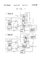
- the LPC synthesis filter 14 and the perceptual weighting filter 21 in FIG. 1A are combined into a perceptual weighting synthesis filter 24 as shown in FIG. 1B.
- the input signal from the input terminal 11 is applied via the perceptual weighting filter 21 to the subtracting means 19.
- the data encoded by the CELP coding scheme is decoded in such a manner as shown in FIG. 2A.
- the LPC coefficient index in the input encoded data fed via an input terminal is decoded by decoding means 32, and the decoded quantized LPC coefficients are used to set filter coefficients in an LPC synthesis filter 33.
- the pitch index in the input encoded data is used to fetch an excitation vector from an adaptive codebook 34, and the noise index in the input encoded data is used to fetch a noise vector from a noise codebook 35.
- the vectors fetched from the two codebooks 34 and 35 are given by gain providing means 36 and 37 gains individually corresponding to gain indexes contained in the input encoded data and then added by adding means 38 into an excitation signal, which is applied to the LPC synthesis filter 33.
- the synthesized signal from the synthesis filter 33 is outputted after being processed by a post-filter 39 so that quantized noise is reduced in view of the human hearing or auditory characteristics.
- the synthesis filter 33 and the post-filter 39 may sometimes be combined into a synthesis filter 41 adapted to meet the human hearing or auditory characteristics.
- the human hearing possesses a masking characteristic that when the level of a certain frequency component is high, sounds of frequency components adjacent thereto are hard to hear. Accordingly,.the error signal from the subtracting means 19 is processed by the perceptual weighting filter 21 so that the signal portion of large power on the frequency axis is lightly weighted and the small power portion is heavily weighted. This is intended to obtain an error signal of frequency characteristics similar to those of the input signal.
- the transfer characteristic f(z) of the perceptual weighting filter 21 there are known as the transfer characteristic f(z) of the perceptual weighting filter 21 the two types of characteristics described below.
- the first type of characteristic can be expressed by equation (1) using a p-order quantized LPC coefficient ⁇ and a constant ⁇ smaller than 1 (0.7, for instance) that are used in the synthesis filter 14.
- the application to the perceptual weighting synthesis filter 24, that is, the application of the excitation vector to the perceptual weighting filter via the synthesis filter means canceling the numerator of the characteristic f(z) and the denominator of the characteristic h(z) with each other; the excitation vector needs only to be applied to a filter of a characteristic expressed below by equation (3)--this permits simplification of the computation involved. ##EQU2##
- the second type of transfer characteristic of the perceptual weighting filter 21 can be expressed below by equation (4) using a p-order LPC coefficients (not quantized) ⁇ derived from the input signal and two constants ⁇ 1 and ⁇ 2 smaller than 1 (0.9 and 0.4, for instance). ##EQU3##
- the postfilter 39 is provided to reduce quantization noise through enhancement in the formant region or in the higher frequency component, and the transfer characteristic f(z) of this filter now in wide use is given by the following equation. ##EQU4## where ⁇ is decoded p-order quantized LPC coefficients, ⁇ is a constant for correcting the inclination of the spectral envelope which is 0.4, for example, and ⁇ 3 and ⁇ 4 are positive constants for enhancing spectral peaks which are smaller than 1, for instance, 0.5 and 0.8, respectively.
- the quantized LPC coefficients ⁇ are used when the input data contains an index representing them as in the case of the CELP coding, and in the case of decoding data encoded by a coding scheme which does not use indexes of this kind, such as a mere ADPCM scheme, the LPC coefficients are obtained by an LPC analysis of the synthesized signal from the synthesis filter.
- the filters in FIGS. 1 and 2 are usually formed as digital filters.
- the filter coefficients can easily be calculated because of utilization of the LPC coefficients therefor, but this requires a great deal of computation.
- the perceptual weighting filter employs only one or two parameters ⁇ or ⁇ 1 and ⁇ 2 for controlling its characteristic, and hence cannot provide a high precision characteristic well suited or adapted to the input signal characteristic.
- the postfilter also uses only three parameters ⁇ , ⁇ 3 and ⁇ 4 to control its characteristic and cannot reflect the human hearing or auditory characteristic with high precision.
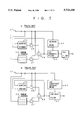
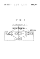
- a digitized acoustic input signal sequence is input from an input terminal 53 into frame split (or signal segmentation) means 54, wherein an input sequence of two by N preceding samples is extracted every N input samples into an input frame of a two-by-N-sample length.
- This input frame is fed into windowing means 55, wherein it is multiplied by a window function.
- the input signal sequence output from the windowing means 55 is modified-discrete-cosine transformed by MDCT (Modified Discrete Cosine Transform) means 56 into an N-sample frequency-domain signal.
- MDCT Modified Discrete Cosine Transform
- the input signal sequence, multiplied by a window function, is LPC analyzed by LPC analysis means 57 to obtain p-order prediction coefficients, which are quantized by quantization means 58.
- This quantization can be done by, for instance, an LSP quantization method that quantizes the prediction coefficients after transforming them into LSP parameters, or a method that quantizes the prediction coefficients after transforming them into k parameters.
- An index representing the quantized prediction coefficients is output from the quantization means 58.
- the quantized prediction coefficients are also provided to frequency spectral envelope calculating means 61, by which their power spectra are calculated to obtain a frequency spectral envelope signal. That is, decoded prediction coefficients ( ⁇ parameters) are FFT-analyzed (Fast Fourier Transform: Discrete Fourier Transform), then the power spectrum is calculated, and a reciprocal of its square root is Calculated to obtain a frequency spectral envelope signal.
- each sample of the frequency-domain signal from the MDCT means 56 is normalized by being multiplied by each sample of the reciprocal of the frequency spectral envelope signal, thereby obtaining a flattened residual signal.
- power normalization/gain quantization means 63 the residual signal is normalized into a normalized residual signal by being divided by an average value of its amplitude, then the amplitude average value is quantized, and an index 64 representing the quantized normalized gain is output.
- the signal from the frequency spectral envelope calculating means 61 which is the reciprocal of the frequency spectral envelope, is controlled by a weight calculating means 65 through the use of a psycho-acoustic model and is rendered into a weighting signal.
- normalized residue quantization means 66 the normalized residual signal from the means 63 is adaptively-weighted vector-quantized by the weighting signal from the means 65.
- An index 67 representing the vector value quantized by the quantization means 66 is output therefrom.
- the encoder 51 outputs the prediction coefficient quantized index 59, the gain quantized index 64 and the residue quantized index 67.
- a decoder 52 decodes these indexes 59, 64 and 67 as described below. That is, the prediction coefficient quantized index 59 is decoded by decoding means 76 into the corresponding quantized prediction coefficients, which are provided to frequency spectral envelope calculating means 77, wherein the reciprocal of the frequency spectral envelope, that is, the reciprocal of the square root of the power spectral envelope is calculated in the same manner as in the frequency spectral envelope calculating means 61.
- the index 67 is decoded by decoding means 79 into the quantized normalized residual signal.
- the index 64 is decoded by decoding means 79 into the normalized gain (average amplitude).
- the quantized normalized residual signal decoded by the decoding means 78, is multiplied by the normalized gain from the decoding means 79 to obtain a power de-normalized quantized residual signal.
- de-normalization inverse processing of flattening
- the quantized residual signal is de-flattened by being divided every sample by the reciprocal of the frequency spectral envelope from the frequency spectral envelope calculating means 77.
- inverse MDCT inverse MDCT means 83 the de-flattened residual signal is transformed into a time-domain signal by being subjected to N-order inverse discrete cosine transform processing.
- windowing means 84 the time-domain signal is multiplied by a window function.
- the output from the windowing means 84 is provided to frame overlapping means 85, wherein former N samples of a 2N-sample long frame and latter N samples of the preceding frame are added to each other, and the resulting N-sample signal is provided to an output terminal 86.
- the coding scheme described above is called a transform coding scheme as well and is suitable for encoding of relatively wideband acoustic signals such as musical signals.
- the decoder 52 decodes the quantized prediction coefficients from the index 59, then calculates their power spectra, then calculates their square root every sample, and calculates a reciprocal of the square root; the calculation of the square root for each sample requires an appreciably large amount of processing and constitutes an obstacle to real-time operation of the decoder on one hand and inevitably involves large-scale, expensive hardware therefor on the other hand.
- the quantization of the LPC coefficients for determining the filter coefficients of the synthesis filter 14 in FIG. 1A is usually carried out after transforming the coefficients into LSP parameters, and in the encoding of wide band speech about 20 orders of LPC coefficients are needed to achieve satisfactory performance.
- the spectral peak of the input data is so sharp that the space between the LSP parameters is very narrow in the course of transforming about 20 orders of LSP parameters into LPC coefficients
- high computational precision is needed, but its implementation is particularly difficult in a fixed-point DSP (Digital Signal Processor). This problem could be solved by using twice a filter with a square root power spectral characteristic, but a high precision square root power spectral envelope cannot be obtained.
- An object of the present invention is to provide a method of modifying LPC coefficients for use in a perceptual weighting filter.
- Another object of the present invention is to provide an LPC coefficient modifying method with which it is possible to control LPC coefficients for use in a perceptual weighting filter more minutely than in the past and to obtain a spectral envelope close to a desired one of an acoustic signal.
- Still another object of the present invention is to provide an LPC coefficient modifying method according to which LPC coefficients for determining coefficients of a filter to perceptually suppress quantization noise can be controlled more minutely than in the past and a spectral envelope close to a desired one of an acoustic signal.
- the present invention is directed to an LPC coefficient modifying method in which p-order LPC coefficients of an acoustic signal are transformed into n-order (where n>p) LPC cepstrum coefficients, then the LPC cepstrum coefficients are modified, and the modified LPC cepstrum coefficients are inversely transformed by the method of least squares into n-order (where m ⁇ n) LPC coefficients in the LPC cepstrum domain.
- the above modification is performed by dividing each order of LPC cepstrum coefficient by two.
- the present invention is directed to an LPC coefficient modifying method which is used in a coding scheme for determining indexes to be encoded in such a manner as to minimize the difference signal between an acoustic input signal and a synthesized signal of the encoded indexes and modifies LPC coefficients for use as filter coefficients of an all-pole or moving average digital filter that performs weighting of the difference signal in accordance with human hearing or auditory or psycho-acoustic characteristics.
- the p-order LPC coefficients of the input signal are transformed into n-order (where n>p) LPC cepstrum coefficients, then the LPC cepstrum coefficients are modified into n-order modified LPC cepstrum coefficients, and the modified LPC cepstrum coefficients are inversely transformed by the method of least squares into new m-order (where m ⁇ n) LPC coefficients for use as the filter coefficients.
- the present invention is directed to an LPC coefficient modifying method which is used in a coding scheme for determining indexes to be encoded in such a manner as to minimize the difference signal between an acoustic input signal and a synthesized signal of the encoded indexes and modifies LPC coefficients for use as filter coefficients of an all-pole or moving average digital filter that synthesizes the above-said synthesized signal and performs its weighting in accordance with human psycho-acoustic characteristics.
- the p-order LPC coefficients ⁇ i of the input signal and their quantized LPC coefficients ⁇ i are respectively transformed into n-order (where n>p) LPC cepstrum coefficients, then the LPC cepstrum coefficients transformed from the LPC coefficients are modified into n-order modified LPC cepstrum coefficients, then the LPC cepstrum coefficients transformed from the quantized LPC coefficients and the modified LPC cepstrum coefficients are added together, and the added LPC cepstrum coefficients are inversely transformed by the method of least squares into new m-order (where m ⁇ n) LPC coefficients for use as the filter coefficients.
- the relationship between the input signal and the corresponding masking function chosen in view of human psycho-acoustic characteristics is calculated in the n-order LPC cepstrum domain and this relationship is utilized for the modification of the LPC cepstrum coefficients.
- the present invention is directed to a method which modifies LPC coefficients for use as filter coefficients of an all-pole or moving average digital filter that perceptually or psycho-acoustically suppresses quantization noise for a synthesized signal of decoded input indexes of coded speech or musical sounds.
- the p-order LPC coefficients derived from the input index are transformed into n-order (where n>p) LPC cepstrum coefficients, then the LPC cepstrum coefficients are modified into n-order modified LPC cepstrum coefficients, and the modified LPC cepstrum coefficients are inversely transformed by the method of least squares into new m-order (where m ⁇ n) LPC coefficients for use as the filter coefficients.
- the present invention is directed to a method which modifies LPC coefficients for use as filter coefficients of an all-pole or moving average digital filter that synthesizes a signal by using p-order LPC coefficients in the input indexes and perceptually or psycho-acoustically suppresses quantization noise for the synthesized signal.
- the p-order LPC coefficients are transformed into n-order (where n>p) LPC cepstrum coefficients, then the LPC cepstrum coefficients are modified into n-order modified LPC cepstrum coefficients, then the modified LPC cepstrum coefficients and the LPC cepstrum coefficients are added together, and the added LPC cepstrum coefficients are inversely transformed by the method of least squares into new m-order (where m ⁇ n) LPC coefficients for use as the filter coefficients.
- the relationship between the input-index decoded synthesized signal and the corresponding enhancement characteristic function chosen in view of human psycho-acoustic characteristics is calculated in the n-order LPC cepstrum domain and this relationship is utilized for the modification of the LPC cepstrum coefficients.
- FIGS. 1A and B are block diagrams showing prior art CELP coding schemes
- FIGS. 2A and B are block diagrams showing prior art CELP coded data decoding schemes
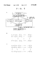
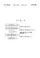
- FIG. 3A is a flowchart showing the procedure of an embodiment according to the first aspect of the present invention.
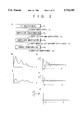
- FIG. 3B is a graph showing an example of a log power spectral envelope of an input signal
- FIG. 3C is a graph showing an example of the log power spectral envelope of a masking function suited to the input signal shown in FIG. 3B;
- FIGS. 3D and E are graphs showing examples of LPC cepstrum coefficients transformed from the power spectral envelopes depicted in FIGS. 3B and C, respectively;
- FIG. 3F is a graph showing the ratio between the corresponding orders of LPC cepstrum coefficients in FIGS. 3D and E;
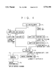
- FIG. 4 is a flowchart illustrating the procedure of an embodiment according to the third aspect of the present invention.
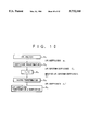
- FIG. 5A is a flowchart illustrating a modified procedure in modification step S 3 in FIG. 3A;
- FIG. 5B is a diagram showing modified LPC cepstrum coefficients C 1 , . . . , C q obtained by multiplying LPC cepstrum coefficients c j by constants ⁇ 1 j , . . . ⁇ q j , respectively, in the processing in the flowchart of FIG. 5A;
- FIG. 5C is a diagram showing respective elements of modified LPC cepstrum coefficients c j obtained by integrating the modified LPC cepstrum coefficients C 1 , . . . , C q ;
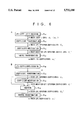
- FIG. 6A is a flowchart showing the procedure of an embodiment according to the fourth aspect of the present invention.
- FIG. 6B is a flowchart showing the procedure of an embodiment according to the fifth aspect of the present invention.
- FIG. 7 is a flowchart showing an example of the procedure in the coefficient modifying step in FIGS. 6A and 6B;
- FIG. 8 is a block diagram illustrating a proposed transform encoder and decoder
- FIG. 9 is a flowchart showing the procedure of the present invention applied to auxiliary coding in the transform coding
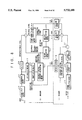
- FIG. 10 is a flowchart showing the procedure of still another embodiment according to the present invention.
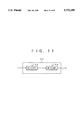
- FIG. 11 is a block diagram illustrating a synthesis filter structure utilizing the modified procedure in FIG. 10.
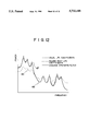
- FIG. 12 is a graph showing examples of power spectral envelopes of various filter outputs.
- FIG. 3A there is shown the general procedure according to the first aspect of the present invention.
- a description will be given first of an application of the present invention to the determination of filter coefficients of an all-pole perceptual weighting filter in the coding scheme shown in FIG. 1A according to the second aspect of the invention.
- the LPC coefficients ⁇ i can be obtained with the LPC analysis means 12 in FIG. 1.
- the next step is to derive n-order LPC cepstrum coefficients c n from the LPC coefficients ⁇ i (S 2 ).
- the procedure for this calculation is performed using the known recursive equation (6) shown below.
- the order p is usually set to 10 to 20 or so, but to reduce a truncation or discretization error, the order n of the LPC cepstrum needs to be twice or three times the order p. ##EQU5##
- the LPC cepstrum coefficient c j are modified for adaptation to the perceptual weighting filter (S 3 ).
- the log power spectral envelope characteristic based on the LPC analysis of an average input signal is such as shown in FIG. 3B and the log power spectral envelope characteristic of a masking function favorable for the above characteristic is such as shown in FIG. 3C
- the log power spectral envelope characteristics of these average input signal and masking function are inverse-Fourier transformed to obtain n-order LPC cepstrum coefficients c j s and c j f such as depicted in FIGS. 3D and E, respectively.
- the modified LPC cepstrum coefficients c j ' are inversely transformed into new m-order LPC coefficients ⁇ i ' (S 4 ), where m is an integer nearly equal to p.
- This inverse transformation can be carried out by reversing the above-relationship between the LPC cepstrum coefficients and the LPC coefficients, but since the number n of modified LPC cepstrum coefficients c j ' is far larger than the number m of LPC coefficients ⁇ j ', there do not exist the LPC coefficients ⁇ j ' from which all the modified LPC cepstrum coefficients c j are derived.
- the method of least squares is used to calculate the LPC coefficients ⁇ j ' that minimize the square of a recursion error e j of each modified LPC cepstrum coefficient c j '.
- the coefficients a i ' are transformed into PARCOR coefficients, for instance, and a check is made to see if the value of each order is within ⁇ 1, by which the stability can be checked.
- the relationship between the new LPC coefficients a 1 ' and the modified LPC cepstrum coefficients c j ' is expressed by such a matrix as follows: ##EQU6##
- the n-order LPC cepstrum coefficients c j are modified according to the relationship between the input signal and its masking function. Since the modification utilizes the aforementioned ratio ⁇ j , the n elements of the LPC cepstrum coefficients c j can all be differently modified and the modified LPC cepstrum coefficients c j ' are inversely transformed into the m-order LPC coefficients ⁇ i '; since in this case every element of the coefficients ⁇ i ' is reflective of the corresponding element of the n-order modified LPC cepstrum coefficients c j ', the new LPC coefficients ⁇ i ' can be regarded as being modified more freely and minutely than in the prior art.
- the first type merely multiplies i-order LPC cepstrum coefficients c i by ⁇ 1 --this only monotonically attenuates the LPC cepstrum coefficients on the quefrency.
- the second type also merely multiplies the i-order LPC cepstrum coefficients c 1 by (- ⁇ 1 i + ⁇ 2 i ).
- the present invention permits individually modifying all the elements of the LPC cepstrum coefficients c i and provides a far higher degree of freedom than in the past; hence, it is possible to minutely control the LPC cepstrum coefficients to undergo slight variations in the spectral envelope while monotonically attenuating them on the quefrency.
- the order m may be set to be larger than p to increase the approximation accuracy of the synthesis filter characteristic or smaller than p to reduce the computational complexity.
- FIG. 4 there is shown the procedure of an embodiment according to the third aspect of the present invention that is applied to the determination of the filter coefficients of the all-pole filter 24 that is a combination of the LPC synthesis filter and the perceptual weighting filter in FIG. 1B.
- the LPC coefficients in this example are those quantized by the quantization means 13 in FIG. 1A, that is, the LPC coefficients ⁇ i are quantized into quantized LPC coefficients ⁇ i (S 5 ).
- the temporal updating of the filter coefficients of the synthesis filter 24 also needs to be synchronized with the timing for outputting the index of the LPC coefficients ⁇ i .
- the filter coefficients of the perceptual weighting filter need not be quantized and the temporal updating of the filter coefficients is also free.
- Either set of LPC coefficients are transformed into n-order LPC cepstrum coefficients c j . That is, the LPC coefficients ⁇ i are transformed into n-order LPC cepstrum coefficients c j (S 2 ) and the quantized LPC coefficients ⁇ 1 are also transformed into n-order LPC cepstrum coefficients c j (S6).
- the perceptual weighting LPC coefficients ⁇ 1 are transformed using, for example, the same masking function as in the case of FIG.
- the n-order LPC cepstrum coefficients c j " are inversely transformed into m-order LPC coefficients of the all-pole synthesis filter as is the case with FIG. 3A (S 4 ).
- the n-order LPC cepstrum coefficients c j " are inversely transformed into m-order LPC coefficients of the all-pole synthesis filter as is the case with FIG. 3A (S 4 ).
- by inverting the polarity of all the LPC cepstrum coefficients c j " (S 15 ) and inversely transforming them into LPC coefficients (S 4 ') as indicated by the broken lines in FIG. 4, it is possible to obtain moving average filter coefficients (FIR filter coefficients an impulse response sequence).
- the number of orders is usually smaller with the all-pole filter than with the moving average one, but latter may sometimes be preferable in terms of stability of the synthesis filter.
- LPC coefficients are derived from input data (S 10 ). That is, as in the decoder of FIG. 2, when the input data contains an index representing quantized LPC coefficients, the index is decoded into p-order quantized LPC coefficients ⁇ i .
- the decoded synthesized signal is LPC-analyzed to obtain the p-order LPC coefficients ⁇ i .
- the LPC coefficients ⁇ i (or ⁇ i ) are transformed into n-order LPC cepstrum coefficients c j (S 11 ). This transformation may be carried out in the same manner as in step S 2 in FIG. 3A.
- the LPC cepstrum coefficients are modified into n-order LPC cepstrum coefficients c j ' (S 12 ). This is performed in the same manner as described previously with respect to FIGS. 3B through E.
- modified LPC cepstrum coefficients c j ' are inversely transformed into m-order LPC coefficients ⁇ i ' to obtain the filter coefficients of the all-pole postfilter 39 (S 13 ), where m is an integer nearly equal to p.
- This inverse transformation takes place in the same manner as in inverse transformation step S 4 in FIG. 3A.
- the present invention permits independent modification of all orders (elements) of the LPC cepstrum coefficients c j transformed from the decoded quantized LPC coefficients and provides a higher degree of freedom than in the past, enabling the characteristic of the postfilter 39 to closely resemble the target enhancement function with higher precision than in the prior art.
- FIG. 6B there is shown an embodiment according to the fifth aspect of the present invention for determining the filter coefficients of the synthesis filter 41 in FIG. 2B formed by integrating the LPC synthesis filter 33 and the postfilter 39 in FIG. 2A.
- p-order LPC coefficients ⁇ i are derived from the input data (S10), then the p-order LPC coefficients ⁇ i are transformed into n-order LPC cepstrum coefficients c j (S 11 ), and the LPC cepstrum coefficients c j are modified into n-order LPC cepstrum coefficients c j ' (S 12 ).
- the modified LPC cepstrum coefficients c j and the non-modified LPC cepstrum coefficients c j are added together for each order to obtain n-order LPC cepstrum coefficients c j " (S 14 ), which are inversely transformed into m-order LPC coefficients ⁇ j ' (S 13 ).
- the moving average filter coefficients may be obtained by inverting the polarity of all the modified LPC cepstrum coefficients c j " and inversely transforming them into LPC coefficients.
- an input acoustic signal is LPC-analyzed for each frame to obtain p-order LPC coefficients ⁇ i , which are transformed into n-order LPC cepstrum coefficients c j (S 2 ) as shown in FIG. 9.
- This transformation can be performed in the same manner as in step S 2 in FIG. 3A.
- the n-order LPC cepstrum coefficients c j ' are multiplied for each order (each element) by 0.5 (divided by 2) to obtain n-order modified LPC cepstrum coefficients c j ' (S 3 ), which are then inversely transformed into p-order LPC coefficients ⁇ i ' (S 4 ).
- This inverse transformation is carried out in the same manner a in step S 4 in FIG. 3A.
- the p-order LPC coefficients ⁇ i ' are quantized for output as an index from the encoder (S 16 ). This index is decoded, though not shown, and as depicted in FIG.
- the decoded LPC coefficients are used to calculate the reciprocal of the square root of the power spectral envelope, then the acoustic input signal is transformed by the square root of the power spectrum envelope into a frequency-domain signal, and its residual signal is vector-quantized. Since in the LPC cepstrum domain the square root of the power spectral envelope is obtained simply by multiplying all orders (all elements) of the coefficients by 0.5, the LPC coefficients ⁇ i ' that are obtained in step S 4 correspond to the square root of the power spectral envelope of the input signal. Hence, decoding the index obtained in step S 15 in the decoder, the coefficients corresponding to the square root of the power spectral envelope of the input signal are obtained, so that no square root calculation is necessary and the computational complexity decreases accordingly.
- the input signal is subjected to, for example, 20 orders of LPC analysis (S 1 ), then the resulting LPC coefficients ⁇ i are transformed into 40 to 80 orders of LPC cepstrum coefficients c j (S 2 ), then each element of the LPC cepstrum coefficients c j is multiplied by 1/2 to obtain modified LPC cepstrum coefficients c j ' (S 3 ), then the modified LPC cepstrum coefficients c j ' are inversely transformed into 20 orders of LPC coefficients ⁇ i ' (S 4 ), then the LPC coefficients ⁇ i ' are transformed into LSP parameters, and the LSP parameters are quantized (S 5 ).
- the quantized LSP parameters are transformed into 20 orders of LPC coefficients to obtain filter coefficients of an autoregressive filter.
- a pair of such filters 14a each having set therein the filter coefficients are connected in cascade to form the LPC synthesis filter 14.
- the LPC spectrum of the output from one filter 14a is such as indicated by the curve 45 in FIG. 12 and the combined LPC spectrum of the outputs from the two filters 14a is such as indicated by the curve 46 in FIG. 12, whereas the LPC spectrum of the output from a conventional single-stage filter is such as indicated by the curve 47.
- the two-stage filter that embodies the present invention provides about the same characteristic as does the conventional single-stage filter of which high computational precision is required.
- the 20th-order filter 14a needs only to be designed for the implementation of the two-stage filter; and since the spectral peaks of the filter characteristic are not sharp, the computational precision required for the filter coefficients through transformation of the LSP into the LPC coefficients is significantly relieved as compared with the computational precision needed in the past, and hence the synthesis filter can be applied even to a fixed-point digital signal processor (DSP).
- DSP digital signal processor
- the LPC coefficients after being transformed into the LPC cepstrum coefficients, are modified in accordance with the masking function and the enhancement function, and the modified LPC cepstrum coefficients are inversely transformed into the LPC coefficients through the use of the method of least squares.
- the LPC coefficients of an order lower than that of the LPC cepstrum coefficients can be obtained as being reflective of the modification in the LPC cepstrum domain with high precision of approximation.
- the computational complexity for the perceptual weighting filter in FIG. 1 is reduced to 1/3 that involved in the case of using Eq. (4).
- the multiplication needs to be done about 2,460,000 times, but according to the present invention, approximately 820,000 times.
- the computation for the transformation into the LPC cepstrum coefficients and for the inverse transformation therefrom is conducted by solving an inverse matrix of a 20 by 20 square matrix, and the number of computations involved is merely on the order of thousands of times.
- the computational complexity in the perceptual weighting synthesis filter accounts for 40 to 50% of the overall computational complexity, the use of the present invention produces a particularly significant effect of reducing the computational complexity.
- each order (each element) of the LPC cepstrum coefficients can be modified individually, and consequently, they can be modified with far more freedom than in the past and with high precision of approximation to desired characteristic. Accordingly, the modified LPC coefficients well reflect the target characteristic and they are inversely transformed into LPC coefficients of a relatively low order--this allows ease in, for instance, determining the filter coefficient and does not increase the order of the filter.
Landscapes
- Engineering & Computer Science (AREA)
- Physics & Mathematics (AREA)
- Spectroscopy & Molecular Physics (AREA)
- Computational Linguistics (AREA)
- Signal Processing (AREA)
- Health & Medical Sciences (AREA)
- Audiology, Speech & Language Pathology (AREA)
- Human Computer Interaction (AREA)
- Acoustics & Sound (AREA)
- Multimedia (AREA)
- Transmission Systems Not Characterized By The Medium Used For Transmission (AREA)
- Compression, Expansion, Code Conversion, And Decoders (AREA)
Applications Claiming Priority (2)
| Application Number | Priority Date | Filing Date | Title |
|---|---|---|---|
| JP05117495A JP3235703B2 (ja) | 1995-03-10 | 1995-03-10 | ディジタルフィルタのフィルタ係数決定方法 |
| JP7-051174 | 1995-03-10 |
Publications (1)
| Publication Number | Publication Date |
|---|---|
| US5732188A true US5732188A (en) | 1998-03-24 |
Family
ID=12879478
Family Applications (1)
| Application Number | Title | Priority Date | Filing Date |
|---|---|---|---|
| US08/612,797 Expired - Lifetime US5732188A (en) | 1995-03-10 | 1996-03-11 | Method for the modification of LPC coefficients of acoustic signals |
Country Status (4)
| Country | Link |
|---|---|
| US (1) | US5732188A (de) |
| EP (1) | EP0731449B1 (de) |
| JP (1) | JP3235703B2 (de) |
| DE (1) | DE69609099T2 (de) |
Cited By (29)
| Publication number | Priority date | Publication date | Assignee | Title |
|---|---|---|---|---|
| US6014620A (en) * | 1995-06-21 | 2000-01-11 | Telefonaktiebolaget Lm Ericsson | Power spectral density estimation method and apparatus using LPC analysis |
| WO2000022605A1 (en) * | 1998-10-14 | 2000-04-20 | Liquid Audio, Inc. | Efficient watermark method and apparatus for digital signals |
| US6188980B1 (en) * | 1998-08-24 | 2001-02-13 | Conexant Systems, Inc. | Synchronized encoder-decoder frame concealment using speech coding parameters including line spectral frequencies and filter coefficients |
| US6202045B1 (en) * | 1997-10-02 | 2001-03-13 | Nokia Mobile Phones, Ltd. | Speech coding with variable model order linear prediction |
| US6209094B1 (en) | 1998-10-14 | 2001-03-27 | Liquid Audio Inc. | Robust watermark method and apparatus for digital signals |
| US6320965B1 (en) | 1998-10-14 | 2001-11-20 | Liquid Audio, Inc. | Secure watermark method and apparatus for digital signals |
| US6330673B1 (en) | 1998-10-14 | 2001-12-11 | Liquid Audio, Inc. | Determination of a best offset to detect an embedded pattern |
| US6330533B2 (en) * | 1998-08-24 | 2001-12-11 | Conexant Systems, Inc. | Speech encoder adaptively applying pitch preprocessing with warping of target signal |
| AU741881B2 (en) * | 1999-11-12 | 2001-12-13 | Motorola Australia Pty Ltd | Method and apparatus for determining paremeters of a model of a power spectrum of a digitised waveform |
| US6345100B1 (en) | 1998-10-14 | 2002-02-05 | Liquid Audio, Inc. | Robust watermark method and apparatus for digital signals |
| AU754612B2 (en) * | 1999-11-12 | 2002-11-21 | Motorola Australia Pty Ltd | Method and apparatus for estimating a spectral model of a signal used to enhance a narrowband signal |
| US20030105627A1 (en) * | 2001-11-26 | 2003-06-05 | Shih-Chien Lin | Method and apparatus for converting linear predictive coding coefficient to reflection coefficient |
| US6594626B2 (en) * | 1999-09-14 | 2003-07-15 | Fujitsu Limited | Voice encoding and voice decoding using an adaptive codebook and an algebraic codebook |
| US20040153789A1 (en) * | 1998-10-13 | 2004-08-05 | Norihiko Fuchigami | Audio signal processing apparatus |
| US20040199381A1 (en) * | 2003-04-01 | 2004-10-07 | International Business Machines Corporation | Restoration of high-order Mel Frequency Cepstral Coefficients |
| KR100488121B1 (ko) * | 2002-03-18 | 2005-05-06 | 정희석 | 화자간 변별력 향상을 위하여 개인별 켑스트럼 가중치를 적용한 화자 인증 장치 및 그 방법 |
| US20050165608A1 (en) * | 2002-10-31 | 2005-07-28 | Masanao Suzuki | Voice enhancement device |
| US20050187762A1 (en) * | 2003-05-01 | 2005-08-25 | Masakiyo Tanaka | Speech decoder, speech decoding method, program and storage media |
| US20060089833A1 (en) * | 1998-08-24 | 2006-04-27 | Conexant Systems, Inc. | Pitch determination based on weighting of pitch lag candidates |
| US20060217983A1 (en) * | 2005-03-28 | 2006-09-28 | Tellabs Operations, Inc. | Method and apparatus for injecting comfort noise in a communications system |
| US20060215683A1 (en) * | 2005-03-28 | 2006-09-28 | Tellabs Operations, Inc. | Method and apparatus for voice quality enhancement |
| US20060217970A1 (en) * | 2005-03-28 | 2006-09-28 | Tellabs Operations, Inc. | Method and apparatus for noise reduction |
| US20060217972A1 (en) * | 2005-03-28 | 2006-09-28 | Tellabs Operations, Inc. | Method and apparatus for modifying an encoded signal |
| US20060217988A1 (en) * | 2005-03-28 | 2006-09-28 | Tellabs Operations, Inc. | Method and apparatus for adaptive level control |
| US20070160154A1 (en) * | 2005-03-28 | 2007-07-12 | Sukkar Rafid A | Method and apparatus for injecting comfort noise in a communications signal |
| US20090287478A1 (en) * | 2006-03-20 | 2009-11-19 | Mindspeed Technologies, Inc. | Speech post-processing using MDCT coefficients |
| US20100023325A1 (en) * | 2008-07-10 | 2010-01-28 | Voiceage Corporation | Variable Bit Rate LPC Filter Quantizing and Inverse Quantizing Device and Method |
| US20100153099A1 (en) * | 2005-09-30 | 2010-06-17 | Matsushita Electric Industrial Co., Ltd. | Speech encoding apparatus and speech encoding method |
| US20150112692A1 (en) * | 2013-10-23 | 2015-04-23 | Gwangju Institute Of Science And Technology | Apparatus and method for extending bandwidth of sound signal |
Families Citing this family (6)
| Publication number | Priority date | Publication date | Assignee | Title |
|---|---|---|---|---|
| JP2002062899A (ja) * | 2000-08-23 | 2002-02-28 | Sony Corp | データ処理装置およびデータ処理方法、学習装置および学習方法、並びに記録媒体 |
| WO2002013183A1 (fr) | 2000-08-09 | 2002-02-14 | Sony Corporation | Procede et dispositif de traitement de donnees vocales |
| US7283961B2 (en) | 2000-08-09 | 2007-10-16 | Sony Corporation | High-quality speech synthesis device and method by classification and prediction processing of synthesized sound |
| JP4517262B2 (ja) * | 2000-11-14 | 2010-08-04 | ソニー株式会社 | 音声処理装置および音声処理方法、学習装置および学習方法、並びに記録媒体 |
| KR100746680B1 (ko) * | 2005-02-18 | 2007-08-06 | 후지쯔 가부시끼가이샤 | 음성 강조 장치 |
| CN112201261B (zh) * | 2020-09-08 | 2024-05-03 | 厦门亿联网络技术股份有限公司 | 基于线性滤波的频带扩展方法、装置及会议终端系统 |
Citations (2)
| Publication number | Priority date | Publication date | Assignee | Title |
|---|---|---|---|---|
| US4811376A (en) * | 1986-11-12 | 1989-03-07 | Motorola, Inc. | Paging system using LPC speech encoding with an adaptive bit rate |
| EP0562777A1 (de) * | 1992-03-23 | 1993-09-29 | Nokia Mobile Phones Ltd. | Verfahren zur Sprachkodierung |
-
1995
- 1995-03-10 JP JP05117495A patent/JP3235703B2/ja not_active Expired - Lifetime
-
1996
- 1996-03-07 EP EP96103581A patent/EP0731449B1/de not_active Expired - Lifetime
- 1996-03-07 DE DE69609099T patent/DE69609099T2/de not_active Expired - Lifetime
- 1996-03-11 US US08/612,797 patent/US5732188A/en not_active Expired - Lifetime
Patent Citations (2)
| Publication number | Priority date | Publication date | Assignee | Title |
|---|---|---|---|---|
| US4811376A (en) * | 1986-11-12 | 1989-03-07 | Motorola, Inc. | Paging system using LPC speech encoding with an adaptive bit rate |
| EP0562777A1 (de) * | 1992-03-23 | 1993-09-29 | Nokia Mobile Phones Ltd. | Verfahren zur Sprachkodierung |
Cited By (55)
| Publication number | Priority date | Publication date | Assignee | Title |
|---|---|---|---|---|
| US6014620A (en) * | 1995-06-21 | 2000-01-11 | Telefonaktiebolaget Lm Ericsson | Power spectral density estimation method and apparatus using LPC analysis |
| US6202045B1 (en) * | 1997-10-02 | 2001-03-13 | Nokia Mobile Phones, Ltd. | Speech coding with variable model order linear prediction |
| US6330533B2 (en) * | 1998-08-24 | 2001-12-11 | Conexant Systems, Inc. | Speech encoder adaptively applying pitch preprocessing with warping of target signal |
| US7072832B1 (en) | 1998-08-24 | 2006-07-04 | Mindspeed Technologies, Inc. | System for speech encoding having an adaptive encoding arrangement |
| US6188980B1 (en) * | 1998-08-24 | 2001-02-13 | Conexant Systems, Inc. | Synchronized encoder-decoder frame concealment using speech coding parameters including line spectral frequencies and filter coefficients |
| US20060089833A1 (en) * | 1998-08-24 | 2006-04-27 | Conexant Systems, Inc. | Pitch determination based on weighting of pitch lag candidates |
| US7266493B2 (en) | 1998-08-24 | 2007-09-04 | Mindspeed Technologies, Inc. | Pitch determination based on weighting of pitch lag candidates |
| US20080319740A1 (en) * | 1998-09-18 | 2008-12-25 | Mindspeed Technologies, Inc. | Adaptive gain reduction for encoding a speech signal |
| US20090164210A1 (en) * | 1998-09-18 | 2009-06-25 | Minspeed Technologies, Inc. | Codebook sharing for LSF quantization |
| US20090024386A1 (en) * | 1998-09-18 | 2009-01-22 | Conexant Systems, Inc. | Multi-mode speech encoding system |
| US20090182558A1 (en) * | 1998-09-18 | 2009-07-16 | Minspeed Technologies, Inc. (Newport Beach, Ca) | Selection of scalar quantixation (SQ) and vector quantization (VQ) for speech coding |
| US20080294429A1 (en) * | 1998-09-18 | 2008-11-27 | Conexant Systems, Inc. | Adaptive tilt compensation for synthesized speech |
| US8620647B2 (en) | 1998-09-18 | 2013-12-31 | Wiav Solutions Llc | Selection of scalar quantixation (SQ) and vector quantization (VQ) for speech coding |
| US8635063B2 (en) | 1998-09-18 | 2014-01-21 | Wiav Solutions Llc | Codebook sharing for LSF quantization |
| US8650028B2 (en) | 1998-09-18 | 2014-02-11 | Mindspeed Technologies, Inc. | Multi-mode speech encoding system for encoding a speech signal used for selection of one of the speech encoding modes including multiple speech encoding rates |
| US9401156B2 (en) | 1998-09-18 | 2016-07-26 | Samsung Electronics Co., Ltd. | Adaptive tilt compensation for synthesized speech |
| US20080147384A1 (en) * | 1998-09-18 | 2008-06-19 | Conexant Systems, Inc. | Pitch determination for speech processing |
| US9269365B2 (en) | 1998-09-18 | 2016-02-23 | Mindspeed Technologies, Inc. | Adaptive gain reduction for encoding a speech signal |
| US9190066B2 (en) | 1998-09-18 | 2015-11-17 | Mindspeed Technologies, Inc. | Adaptive codebook gain control for speech coding |
| US7801314B2 (en) | 1998-10-13 | 2010-09-21 | Victor Company Of Japan, Ltd. | Audio signal processing apparatus |
| US7136491B2 (en) * | 1998-10-13 | 2006-11-14 | Victor Company Of Japan, Ltd. | Audio signal processing apparatus |
| US20040153789A1 (en) * | 1998-10-13 | 2004-08-05 | Norihiko Fuchigami | Audio signal processing apparatus |
| US20070053521A1 (en) * | 1998-10-13 | 2007-03-08 | Victor Company Of Japan, Ltd. | Audio signal processing apparatus |
| US6330673B1 (en) | 1998-10-14 | 2001-12-11 | Liquid Audio, Inc. | Determination of a best offset to detect an embedded pattern |
| US6345100B1 (en) | 1998-10-14 | 2002-02-05 | Liquid Audio, Inc. | Robust watermark method and apparatus for digital signals |
| US6320965B1 (en) | 1998-10-14 | 2001-11-20 | Liquid Audio, Inc. | Secure watermark method and apparatus for digital signals |
| US6219634B1 (en) | 1998-10-14 | 2001-04-17 | Liquid Audio, Inc. | Efficient watermark method and apparatus for digital signals |
| US6209094B1 (en) | 1998-10-14 | 2001-03-27 | Liquid Audio Inc. | Robust watermark method and apparatus for digital signals |
| WO2000022605A1 (en) * | 1998-10-14 | 2000-04-20 | Liquid Audio, Inc. | Efficient watermark method and apparatus for digital signals |
| US6594626B2 (en) * | 1999-09-14 | 2003-07-15 | Fujitsu Limited | Voice encoding and voice decoding using an adaptive codebook and an algebraic codebook |
| AU754612B2 (en) * | 1999-11-12 | 2002-11-21 | Motorola Australia Pty Ltd | Method and apparatus for estimating a spectral model of a signal used to enhance a narrowband signal |
| AU741881B2 (en) * | 1999-11-12 | 2001-12-13 | Motorola Australia Pty Ltd | Method and apparatus for determining paremeters of a model of a power spectrum of a digitised waveform |
| US20030105627A1 (en) * | 2001-11-26 | 2003-06-05 | Shih-Chien Lin | Method and apparatus for converting linear predictive coding coefficient to reflection coefficient |
| KR100488121B1 (ko) * | 2002-03-18 | 2005-05-06 | 정희석 | 화자간 변별력 향상을 위하여 개인별 켑스트럼 가중치를 적용한 화자 인증 장치 및 그 방법 |
| US7152032B2 (en) | 2002-10-31 | 2006-12-19 | Fujitsu Limited | Voice enhancement device by separate vocal tract emphasis and source emphasis |
| CN100369111C (zh) * | 2002-10-31 | 2008-02-13 | 富士通株式会社 | 话音增强装置 |
| US20050165608A1 (en) * | 2002-10-31 | 2005-07-28 | Masanao Suzuki | Voice enhancement device |
| US20040199381A1 (en) * | 2003-04-01 | 2004-10-07 | International Business Machines Corporation | Restoration of high-order Mel Frequency Cepstral Coefficients |
| US7305339B2 (en) * | 2003-04-01 | 2007-12-04 | International Business Machines Corporation | Restoration of high-order Mel Frequency Cepstral Coefficients |
| US7606702B2 (en) | 2003-05-01 | 2009-10-20 | Fujitsu Limited | Speech decoder, speech decoding method, program and storage media to improve voice clarity by emphasizing voice tract characteristics using estimated formants |
| US20050187762A1 (en) * | 2003-05-01 | 2005-08-25 | Masakiyo Tanaka | Speech decoder, speech decoding method, program and storage media |
| US20060217988A1 (en) * | 2005-03-28 | 2006-09-28 | Tellabs Operations, Inc. | Method and apparatus for adaptive level control |
| US20070160154A1 (en) * | 2005-03-28 | 2007-07-12 | Sukkar Rafid A | Method and apparatus for injecting comfort noise in a communications signal |
| US20060217972A1 (en) * | 2005-03-28 | 2006-09-28 | Tellabs Operations, Inc. | Method and apparatus for modifying an encoded signal |
| US20060217970A1 (en) * | 2005-03-28 | 2006-09-28 | Tellabs Operations, Inc. | Method and apparatus for noise reduction |
| US20060215683A1 (en) * | 2005-03-28 | 2006-09-28 | Tellabs Operations, Inc. | Method and apparatus for voice quality enhancement |
| US20060217983A1 (en) * | 2005-03-28 | 2006-09-28 | Tellabs Operations, Inc. | Method and apparatus for injecting comfort noise in a communications system |
| US20100153099A1 (en) * | 2005-09-30 | 2010-06-17 | Matsushita Electric Industrial Co., Ltd. | Speech encoding apparatus and speech encoding method |
| US20090287478A1 (en) * | 2006-03-20 | 2009-11-19 | Mindspeed Technologies, Inc. | Speech post-processing using MDCT coefficients |
| US8095360B2 (en) * | 2006-03-20 | 2012-01-10 | Mindspeed Technologies, Inc. | Speech post-processing using MDCT coefficients |
| US9245532B2 (en) * | 2008-07-10 | 2016-01-26 | Voiceage Corporation | Variable bit rate LPC filter quantizing and inverse quantizing device and method |
| US20100023325A1 (en) * | 2008-07-10 | 2010-01-28 | Voiceage Corporation | Variable Bit Rate LPC Filter Quantizing and Inverse Quantizing Device and Method |
| USRE49363E1 (en) * | 2008-07-10 | 2023-01-10 | Voiceage Corporation | Variable bit rate LPC filter quantizing and inverse quantizing device and method |
| US20150112692A1 (en) * | 2013-10-23 | 2015-04-23 | Gwangju Institute Of Science And Technology | Apparatus and method for extending bandwidth of sound signal |
| US9460733B2 (en) * | 2013-10-23 | 2016-10-04 | Gwangju Institute Of Science And Technology | Apparatus and method for extending bandwidth of sound signal |
Also Published As
| Publication number | Publication date |
|---|---|
| JP3235703B2 (ja) | 2001-12-04 |
| DE69609099D1 (de) | 2000-08-10 |
| EP0731449B1 (de) | 2000-07-05 |
| EP0731449A3 (de) | 1997-08-06 |
| JPH08248996A (ja) | 1996-09-27 |
| DE69609099T2 (de) | 2001-03-22 |
| EP0731449A2 (de) | 1996-09-11 |
Similar Documents
| Publication | Publication Date | Title |
|---|---|---|
| US5732188A (en) | Method for the modification of LPC coefficients of acoustic signals | |
| KR100421226B1 (ko) | 음성 주파수 신호의 선형예측 분석 코딩 및 디코딩방법과 그 응용 | |
| CA2031006C (en) | Near-toll quality 4.8 kbps speech codec | |
| US5684920A (en) | Acoustic signal transform coding method and decoding method having a high efficiency envelope flattening method therein | |
| RU2389085C2 (ru) | Способы и устройства для введения низкочастотных предыскажений в ходе сжатия звука на основе acelp/tcx | |
| KR100433608B1 (ko) | 음성처리시스템및그의이용방법 | |
| JP3481390B2 (ja) | 短期知覚重み付けフィルタを使用する合成分析音声コーダに雑音マスキングレベルを適応する方法 | |
| KR101039343B1 (ko) | 디코딩된 음성의 피치 증대를 위한 방법 및 장치 | |
| US6813602B2 (en) | Methods and systems for searching a low complexity random codebook structure | |
| JP4662673B2 (ja) | 広帯域音声及びオーディオ信号復号器における利得平滑化 | |
| EP1141946B1 (de) | Kodierung eines verbesserungsmerkmals zur leistungsverbesserung in der kodierung von kommunikationssignalen | |
| JP5978218B2 (ja) | 低ビットレート低遅延の一般オーディオ信号の符号化 | |
| US7490036B2 (en) | Adaptive equalizer for a coded speech signal | |
| Chen et al. | Transform predictive coding of wideband speech signals | |
| EP0878790A1 (de) | Sprachkodiersystem und Verfahren | |
| EP1788555A1 (de) | Sprachcodierungseinrichtung, sprachdecodierungseinrichtung und verfahren dafür | |
| US20070147518A1 (en) | Methods and devices for low-frequency emphasis during audio compression based on ACELP/TCX | |
| Lefebvre et al. | High quality coding of wideband audio signals using transform coded excitation (TCX) | |
| US5884251A (en) | Voice coding and decoding method and device therefor | |
| JPH10124092A (ja) | 音声符号化方法及び装置、並びに可聴信号符号化方法及び装置 | |
| JP2645465B2 (ja) | 低遅延低ビツトレート音声コーダ | |
| Koishida et al. | A wideband CELP speech coder at 16 kbit/s based on mel-generalized cepstral analysis | |
| JP3163206B2 (ja) | 音響信号符号化装置 | |
| Nakatoh et al. | Low bit rate coding for speech and audio using mel linear predictive coding (MLPC) analysis | |
| Patel | Low complexity VQ for multi-tap pitch predictor coding |
Legal Events
| Date | Code | Title | Description |
|---|---|---|---|
| AS | Assignment |
Owner name: NIPPON TELEGRAPH AND TELEPHONE CORPORATION, JAPAN Free format text: ASSIGNMENT OF ASSIGNORS INTEREST;ASSIGNORS:MORIYA, TAKEHIRO;MANO, KAZUNORI;MIKI, SATOSHI;AND OTHERS;REEL/FRAME:007901/0732 Effective date: 19960301 |
|
| STCF | Information on status: patent grant |
Free format text: PATENTED CASE |
|
| FPAY | Fee payment |
Year of fee payment: 4 |
|
| FPAY | Fee payment |
Year of fee payment: 8 |
|
| FPAY | Fee payment |
Year of fee payment: 12 |