US5724499A - Image generating apparatus - Google Patents
Image generating apparatus Download PDFInfo
- Publication number
- US5724499A US5724499A US08/369,110 US36911095A US5724499A US 5724499 A US5724499 A US 5724499A US 36911095 A US36911095 A US 36911095A US 5724499 A US5724499 A US 5724499A
- Authority
- US
- United States
- Prior art keywords
- image
- action
- unit
- information
- generating apparatus
- Prior art date
- Legal status (The legal status is an assumption and is not a legal conclusion. Google has not performed a legal analysis and makes no representation as to the accuracy of the status listed.)
- Expired - Lifetime
Links
Images


Classifications
-
- G—PHYSICS
- G11—INFORMATION STORAGE
- G11B—INFORMATION STORAGE BASED ON RELATIVE MOVEMENT BETWEEN RECORD CARRIER AND TRANSDUCER
- G11B27/00—Editing; Indexing; Addressing; Timing or synchronising; Monitoring; Measuring tape travel
- G11B27/02—Editing, e.g. varying the order of information signals recorded on, or reproduced from, record carriers
- G11B27/031—Electronic editing of digitised analogue information signals, e.g. audio or video signals
- G11B27/034—Electronic editing of digitised analogue information signals, e.g. audio or video signals on discs
Definitions
- the present invention relates to an image generating apparatus using a computer, and more particularly, to an image generating apparatus capable of providing experiences as if in the real world by generating successive images using some visual illusions (hereinafter called "fake”) from a limited number of high-quality image patterns captured into the computer.
- the present invention is intended to resolve the problems associated with the prior art, and it is an object of the invention to provide an image generating apparatus that is capable of generating images using some visual fakes from a finite number of successive image patterns captured into a computer so that successive movements of the images being generated by calculation in the computer look natural to the participant engaged in dialogue (interaction) with the computer.
- an arbitrary image for example, a character
- FIGS. 1A and 1B are diagrams for explaining the principle of the present invention.
- FIGS. 2A and 2B are diagrams illustrating the system configuration according to an embodiment of the present invention.
- FIGS. 3A, 3B, and 3C are diagrams for explaining the concept of image sequence connection according to the embodiment of the present invention.
- FIGS. 4A, 4B, and 4C are diagrams showing specific examples of image sequence connection using key frames according to the embodiment of the present invention.
- FIGS. 5A, 5B, 5C, and 5D are diagrams for explaining the operation of image selection according to the embodiment of the present invention.
- FIG. 6 is a diagram for explaining image generation using key Frames according to the embodiment of the present invention.
- FIGS. 7A, 7B, and 7C are diagrams for explaining the concept of a positional fake according to the embodiment of the present invention.
- FIGS. 8A, 8B, and 8C are diagrams for explaining the positional fake according to the embodiment of the present invention.
- FIGS. 9A and 9B are diagrams for explaining thinning-in-time according to the embodiment of the present invention.
- FIG. 10 is a diagram showing the organization of an information storage unit for thinning-in-time according to the embodiment of the present invention.
- FIG. 11 is a diagram showing the internal configuration of an image generating apparatus according to the present invention.
- FIGS. 12A and 12B are diagrams for explaining actually shot image data and a rim
- FIG. 13 is a flowchart illustrating a process for image generation data creation
- FIG. 14 is a diagram showing a display screen
- FIG. 15 is a flowchart illustrating a process for movement allowable area designation
- FIGS. 16A, 16B, 16C, and 16D are diagrams for explaining movement allowable area designation
- FIGS. 17A and 17B are diagrams for explaining priority designation
- FIG. 18 is a flowchart illustrating a process for image generation data extraction
- FIG. 19 is a diagram for explaining another example of priority designation
- FIG. 20 is a diagram showing the relationship between action patterns and key rims
- FIG. 21 is a flowchart illustrating a process of image generation for an optimum action according to the embodiment of the invention.
- FIGS. 22A and 22B are explanatory diagrams of the principle of a partial graph
- FIG. 23 is a diagram for explaining a partial graph
- FIGS. 24A, 24B, and 24C are explanatory diagrams of the principle of a total graph
- FIG. 25 is a diagram for explaining a total graph
- FIG. 26 is a diagram showing a sorted table
- FIGS. 27A and 27B are diagrams showing transfer tables
- FIG. 28 is a diagram showing the organization of the information storage unit for image selection according to the embodiment of the present invention.
- FIG. 29 is a flowchart illustrating a process of image generation
- FIG. 30 is a diagram showing an evaluation chart
- FIG. 31 is a diagram showing the flow of a plurality of image information items
- FIG. 32 is a diagram showing arm example of a combined image of a plurality of image information items
- FIG. 33 is a diagram for explaining the relationship between a main action and a sub-action according to an embodiment of the present invention.
- FIG. 34 is a diagram showing the organization of the information storage unit for the main action and the sub-action according to the embodiment of the present invention.
- FIG. 35 is a diagram showing an action table
- FIG. 36 is a diagram showing a movement table of a first example
- FIG. 37 is a diagram showing a path candidate of the first example
- FIG. 38 is a diagram showing a movement table of a second example
- FIG. 39 is a diagram showing path candidates of the second example.
- FIG. 40 is a flowchart illustrating a process of image generation
- FIG. 41 is a diagram showing the relationship between an image generating apparatus and an action determining section
- FIG. 42 is a message transfer diagram illustrating the exchange of messages between the image generating apparatus and the lower action determining section for explaining a problem involved;
- FIG. 43 is a message transfer diagram illustrating the exchange of messages between the image generating apparatus and the lower action determining section according to the embodiment of the present invention.
- FIG. 44 is a message transfer diagram illustrating the exchange of messages among the image generating apparatus, the lower action determining section, and a higher action determining section according to the embodiment of the present invention.
- FIG. 45 is a message transfer diagram illustrating the exchange of messages between the image generating apparatus and the lower action determining section in a normal action
- FIG. 46 is a message transfer diagram illustrating the exchange of messages between the image generating apparatus and the lower action determining section in a sudden action
- FIG. 47 is a diagram showing an action pattern
- FIG. 48 is a message transfer diagram illustrating the exchange of messages between the image generating apparatus and the lower action determining section when the change of action has been made successfully;
- FIG. 49 is a message transfer diagram illustrating the exchange of messages between the image generating apparatus and the lower action determining section when the change of action has failed;
- FIG. 50 is a message transfer diagram illustrating the exchange of messages between the image generating apparatus and the lower action determining section for a planned action.
- FIGS. 51A and 51B are diagrams illustrating the flow of messages and the operation of the image generating apparatus, and the lower action determining section, and higher action determining section.
- FIGS. 1A and 1B present diagrams for explaining the principle of the invention, where FIG. 1A shows a system configuration according to the invention.
- the image generating apparatus 1 of the invention has a command interpreting unit 2, an image selecting unit 3, an image display unit 4, and an information storage unit 5.
- the command interpreting unit 2 determines the way how commands for generating intended images should be interpreted within the image generating apparatus 1. Based on fake information, and in accordance with the content of interpretation supplied from the command interpreting unit 2, the image selecting unit 3 selects and determines an image within a range that does not produce unnatural visual effects from the images stored in the information storage unit 5.
- the image display unit 4 displays the image information selected and determined by the image selecting unit 3.
- the information storage unit 5 includes an image information unit 51, as database, and a fake information unit 52.
- image information unit 51 image sequences used for image generation are prestored, such as images of a purpose action, interpolation action, etc. hereinafter described. Fundamental position information and time information which are directly related to image information, information which indicates the feature of images, or the like are often added to the image sequences in the image information unit 51.
- the fake information unit 52 stores fake information in corresponding relationship to the images stored in the image information unit 51.
- the fake information includes similarity information used when linking image sequences together, positional drift information indicating positional drift allowable areas, and thinning-in-time information for thinning or adding frames in an image sequence to accomplish time-scale adjustment when displaying the image sequence.
- FIG. 1B is a diagram for explaining natural moving actions.
- examples of purpose action and interpolation action respectively, are shown; image information relating to these actions is stored in the image information unit 51.
- Actions such as "Greeting” A, "Looking around” B, “Surprising” C, “Eating” D, and “Dancing” E, are called purpose actions and interpolation actions, such as “Moving” F and “Rotating” G, are used to link these purpose actions together.
- a command for generating an intended image is inputted to the command interpreting unit 2, which determines the way how the command should be interpreted within the image generating apparatus 1.
- the following description deals with an example in which a command requesting to link tile purpose action of "Greeting" A with the purpose action of "Looking around” B is accepted by the command interpreting unit 2.
- the image selecting unit 3 compares, for example, the last frame of "Greeting” A with the first frame of "Looking around” B stored in the image information storage unit 5 on the basis of their corresponding fake information stored in the fake information unit 52. If the result of the comparison shows that the last frame is similar to the first frame, these can be connected directly. On the other hand, if there is a positional displacement between the two frames, for example, correction of the positional displacement is made by inserting between these two frames frames of "Movement” F, for example, which is an interpolation action that does not produce unnatural visual effects. When linking actions, making correction to the extent that unnatural visual effects are not caused is called adaptation. Using this technique, the image of "Greeting" A can be connected continuously with the image of "Looking around" B.
- the same image can be used in various kinds of scenes.
- this increases the degree of freedom of action representation for the creature.
- the images are not limited in application to two-dimensional monoscopic image representation but can also be used for three-dimensional image display (e.g., two-images stereoscopic view, lenticular method, and holography).
- FIG. 2A is a diagram showing the configuration of an image generating apparatus using similarity information according to one embodiment of the invention.
- the same parts as those shown in FIG. 1A are designated by the same reference numerals.
- the image generating apparatus of this embodiment has a command interpreting unit 2, an image selecting unit 3, an image display unit 4, and an information storage unit 5.
- the information storage unit 5 includes an image information unit 51 for storing image information, and a similarity information unit 52-1 for storing similarity information.
- FIG. 2B is a diagram for explaining the information storage area 5. As shown, the information storage unit 5 stores image sequences A, B, C, . . .
- N and the similarity information corresponding to each image information that indicates image similarity, that is, similarity to other image information (frames) in shape, position, direction, time, etc.
- similarity information are "N1 frame is similar to A3 frame", “N1 frame is x % similar in image information (shape) to A3 frame”, “N1 frame is similar in direction to A3 frame”, “N1 frame is similar in motion vector to A3 frame”, and so on.
- Such similarity information is stored in corresponding relationship to the frames of the image information. It is of course possible to store similarity information associated with all image information frames.
- FIGS. 3A, 3B, and 3C show the concept of image sequence connection.
- FIG. 3A is a diagram for explaining two actions, action P0 and action P1, representing a continuous action (hereinafter called the "chain action").
- Action P0 is an action moving from start point s0 toward end point e0
- action P1 is an action moving from start point s1 toward end point e1.
- t0 and t1 are the times that actions P0 and P1 take to complete their respective motions.
- FIG. 3B is a diagram for explaining combinational connection, showing how the two actions P0 and P1 are combined for connection.
- key frame b exists at the intersection of action P0 and P1
- action P0 can be connected continuously with action P1 by linking s1 ⁇ b ⁇ e0.
- FIG. 3C is a diagram for explaining connection by frame interpolation; in the example shown in FIG. 3C, key frame b does not exist at the intersection.
- a continuous interpolation action for linking key frames b1 and b2 spaced apart on actions P0 and P1 is selected from the information storage unit 5, and the actions are connected continuously by linking s0 ⁇ b1 ⁇ b2 ⁇ e1.
- FIGS. 4A, 4B, and 4C are diagrams for explaining specific examples of image connection using key frames.
- square boxes in each image sequence indicate the key frames, and dashed lines imply the existence of continuous images.
- FIG. 4A is a diagram for explaining the case where the last frame in one image sequence is connected with the first frame in the next image sequence.
- the last frame f1 in the preceding image sequence A is similar to the first frame f1 in the following image sequence B.
- an image moving continuously from the preceding image sequence A to the following image sequence B can be generated by connecting the last and first frames of the respective image sequences.
- FIG. 4B is a diagram for explaining the case where two image sequences are connected at their intermediate points.
- an intermediate frame in the preceding image sequence A and an intermediate frame in the following image sequence B, which are similar to each other, are detected, and the two image sequences are connected together where the similar frames f1 appear.
- An image moving continuously from the preceding image sequence A to the following image sequence B can be generated in this manner.
- FIG. 4C is a diagram for explaining interpolation connection.
- an interpolation is made by inserting an image sequence C having a similar frame f1 and a similar frame f2 for connection to the preceding image sequence A and the following image sequence B, respectively. That is, at the frame f1 in the preceding image sequence A, a transfer is made to the inserted image sequence C, and at the frame f2 in the inserted image sequence C, a transfer is made to the following image sequence B.
- the interpolating image sequence C an image moving continuously from the preceding image sequence A to the following image sequence B can be generated.
- connection is made using the similar frame f1 or f2
- two similar frames will be displayed in succession.
- the first frame in the connecting image sequence may be dropped from the resulting image sequence.
- FIGS. 5A, 5B, 5C, and 5D are diagrams for explaining the operation when linking two image sequences by connecting the last frame in one image sequence with the first frame in the next image sequence.
- the example shown in FIGS. 5A through 5D corresponds to the image sequence connection shown in FIG. 4A.
- FIG. 5A shows image sequence A, for example, an image sequence for "Hello”.
- This image sequence A is provided with similarity information a, for example, "Standing", at the head, and similarity information b, for example, "Sitting", at the end of the sequence.
- similarity information a for example, "Standing"
- similarity information b for example, "Sitting"
- FIG. 5B shows image sequence D, for example, an image sequence for "Good-by”, and similarity information a and similarity information c, for example, "Facing to the right", are provided for the first and last frames, respectively.
- FIG. 5C shows image sequence E, for example, an image sequence for "Good-by”, and similarity information b and similarity information c are provided for the first and last frames, respectively.
- Image sequence connection will be described below by taking the above image sequences A, D, and E as an example.
- the command content fed from the command interpreting unit 2 requests that the image sequence A for "Hello” be followed by an image sequence for "Good-by".
- the image selecting unit 3 first selects images for "Good-by" from the images stored in the information storage unit 5.
- two image sequences, D and E are selected.
- the image selecting unit 3 retrieves similarity information b for the last frame of the image sequence A from the similarity information unit 52-1, and the first frames a and b of the image sequences D and E for comparison with the similarity information b.
- the image selecting unit 3 selects the image sequence E whose first frame is similar to the last frame of the image sequence A. In this manner, the image sequence A for "Hello” and the image sequence E for "Good-by” can be displayed continuously, as shown in FIG. 5D.
- the image selecting unit 3 selects frames similar between intermediate key frames of the two image sequences A and B on the basis of the information retrieved from the similarity information unit 52-1.
- the image selecting unit 3 selects the image sequence C having frames f1 and f2 similar to the last frame f1 of the image sequence A and the first frame f2 of the image sequence B, on the basis of the information retrieved from the similarity information unit 52-1. In this manner, the image sequences A and B can be displayed continuously, as shown in FIGS. 4B and 4C.
- FIG. 6 is a diagram for explaining image generation using key frames.
- the following explanation assumes that the object image in FIG. 6 is a child.
- a "moving" image is being generated.
- key frame f1 a command "Look around” is issued, and a transfer is made to the next image sequence for "Looking around”. This transfer is made via the key frame f1 in the two image sequences, and the image flow at this time is natural and free from discontinuity.
- a new command "Move obliquely in forward direction” is issued, and a transfer is made via the key frame f2 to an image sequence for "Moving obliquely in forward direction”.
- a command "Surprise” is issued at a point between f3 and f2, as in the above case, but the image sequence for "Greeting" is not at the appropriate point for dividing.
- "Surprise” action should be represented immediately and the immediate representation degree of the "Surprise” command is high, a transfer is made to an image sequence for "Surprising” the instant the command is issued, though the frame continuity will be lost. This is effective for interactive representation.
- a command "Dance” is issued at key frame f3, but the image sequence for "Dancing” starts with the key frame f2. If they are connected directly, image continuity will be lost.
- an image sequence for "Rotating” is used to interpolate between the key frames f3 and f2, to make the connection look natural.
- a command "Eat” is issued at key frame f2, and a transfer is made to an image sequence for "Eating” via the key frame f2 in this image sequence.
- a command "Stay idle” is issued at key frame f4 in this image sequence.
- This key frame f4 is similar to the key frame f4 in the image sequence for "Staying idle", but if these two actions are separated in time, place, etc., an image sequence for "Tripping" is inserted between them. In this manner, naturally flowing images can be generated without loosing continuity even in such a case.
- FIGS. 7A, 7B, 7C, and 7D show the concept of positional fake.
- FIG. 7A is a diagram for explaining action P0 which is moving from start point s0 toward end point (target position) e0.
- FIG. 7B is a diagram for explaining the allowable area for fake by geometric transformation.
- action P0 moving from s0 toward e0 can be moved in parallel direction to fake as action p1 moving from s1 toward e1.
- action P0 moving from s0 toward e0 can be reduced or magnified in the depth direction to fake as action P2 moving from s2 toward e2.
- FIG. 7C is a diagram for explaining perceptual fake.
- FIG. 7C shows that the final end point e0 of action P0 moving from s0 toward e0 can be faked within a range from e1 to e2.
- each image frame of action P0 moving from s0 toward e0 is drifted by positional drift allowable area ⁇ . This generates the image of action P1 moving from s0 toward e1.
- the image of action P2 moving from s0 toward e2 can be generated.
- FIGS. 8A, 8B, and 8C are diagrams for explaining positional fake.
- FIG. 8A is a diagram for explaining the positional drift allowable area for an action moving from start point s1 toward end point e0.
- action P1 from s1 to b and action P0 from b to e0 are shown.
- f1 to f6 are representative frames of actions P1 and P0, and crosshatch in each of the frames f1 to f6 indicates the positional drift allowable area for the frame.
- the positional drift allowable area varies depending on the direction, velocity, magnitude, etc. of the action concerned; for example, the area is small when the footstep is small, and is large when the action concerns a running motion.
- a positional drift allowable area ⁇ is shown along the paths of actions P1 and P0. If the target position is within this positional drift allowable area, an image that can reach the target position can be generated by drifting each frame, starting from s1, by a small amount.
- FIG. 8B is a diagram for explaining the positional drift allowable area for one frame f.
- the positional drift allowable area ⁇ with respect to the image center is shown.
- FIG. 8B is for a two-dimensional image; in the case of a three-dimensional image, the positional drift allowable area is provided for each of X, Y, and Z axes. In this case, for a positional drift in the depth direction, reduction or magnification is performed to prevent the image from looking unnatural.
- FIG. 8C is a diagram for explaining the information storage unit 5 for positional fake.
- a positional drift information unit 52-2 is provided for storing positional drift allowable area information which corresponds to the fake information in the fake information unit 52 shown in FIG. 1A.
- the positional drift allowable area information is provided for each image sequence stored in the image information unit 51, and in frame-by-frame corresponding relationship.
- the image selecting unit 3 when generating an image of action P1 moving from s0 toward e1 shown in FIG. 7C, for example, the image selecting unit 3 first selects, from the information stored in the information storage unit 5, action P0 moving from s0 toward e0 within the positional drift allowable area. Next, based on the positional drift allowable area information for each frame of this action P0, the image selecting unit 3 generates an image with each frame of action P0 drifted in position. In this manner, the image of action P1 can be generated from the image of action P0.
- the entire positional drift allowable area ⁇ for one image sequence can be calculated by summing the positional drift allowable areas ⁇ for the frames of the image sequence at the time of image sequence selection, but can also be prestored for each image sequence in the positional drift information unit 52-2.
- generation of a positionally drifted image is performed by allocating the entire positional drift allowable area ⁇ to the respective frames of the original image. This allocation can be done equally for any frame of a given action, or adaptively in accordance with a certain function. It is also possible to store positional drift allowable area information in the positional drift information unit 52-2 only for the characteristic portions (for example, the key frames) of image information.
- the positional drift allowable area when the positional drift allowable area is needed for each frame, it can be obtained by interpolation, etc. Furthermore, the positional drift allowable area can be expressed not only by a rectangle but also by an ellipse or other shape. In the case of a three-dimensional image, the area can be expressed as an ellipse.
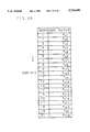
- FIG. 9A is a diagram for explaining an example of thinning in time.
- image sequence A consists, for example, of 10 frames, 1 to 10, as shown, and that the duration of image display is one second.
- Each frame is provided with thinning-in-time priority.
- Image sequence A1 is the result of thinning frames of image sequence A at same intervals. In this case, the duration of display is reduced to 0.5 second.
- image sequence A2 results. In this case, low-priority frames whose priority is 3 are dropped. As a result, the duration of display time of image sequence A2 is reduced to 0.7 second.
- the image sequence A consists of "walk”, “stop”, and “run” actions in sequence starting with frame 1 and ending with frame 10. High priority "1” is assigned to “stop” action, and low priority “3” is assigned to "walk” and “run” actions. With this priority assignment, frames can be thinned within a range that does not cause unnatural visual effects, as shown by image sequence A2.
- the duration of image display is reduced by thinning frames of image sequence, but it is also possible to increase the duration of image display by inserting frames.
- FIG. 10 is a diagram for explaining the information storage unit 5 for thinning in time.
- a thinning-in-time information unit 52-3 is provided for storing thinning-in-time information which corresponds to the fake information in the fake information unit 52 shown in FIG. 1A.
- the thinning-in-time information is stored in corresponding relationship to each image sequence of image information stored in the image information unit 51.
- the thinning-in-time information contains thinning priority of each frame in each image sequence and the time-scale adjustment allowable area for each image sequence.
- the image selecting unit 3 first examines the time-scale adjustment allowable area (in this example, 0.5 to 1.2 seconds) for the image sequence A. Since 0.7 second is within the time-scale adjustment allowable area, the image selecting unit 3 generates the image sequence A2 by dropping low-priority frames in image sequence A. In the case of thinning in time for reducing the duration of image display, high-priority frames are interpolated at appropriate display positions so that the image does not look unnatural (to the eye).
- the time-scale adjustment allowable area in this example, 0.5 to 1.2 seconds
- FIG. 11 is a block diagram showing one embodiment of an apparatus for setting the positional drift allowable area and performing the thinning in time as described above.
- a processing device 21 is, for example, a workstation which carries out processing to create data for image generation.
- An input device 22 is, for example, a keyboard which is used to input commands, numeric values, etc. to the processing device 21.
- a display device 24 is, for example, a CRT display for displaying images on the screen.
- a pointing device 25 is, for example, a mouse which designates the cursor position displayed on the display device 24 and sends signals to the processing device 21.
- the processing device 21 reads out actually shot image data from a storage device 26, for example, a hard disk drive, creates data for image generation, and stores the image data of a character image (frame) extracted from the actually shot image data into a storage device 27, while other data for the extracted character, such as the three-dimensional position, movement, allowable area, total graph, sorted table, and transfer table described hereinafter, are stored into a storage device 28.
- a storage device 26 for example, a hard disk drive
- the actually shot image data is the data created by shooting the action of an animation character on a designated background color such as blue by using a fixed-angle camera.
- FIG. 12A shows the actually shot image data in the form of a movie film, each frame of which is two-dimensional as shown in FIG. 12B.
- the character can be extracted by removing the background color.
- the rectangle which is circumscribed about the character and is a part of frame used for the purpose of designating one unit of fake is called the rim.
- the three-dimensional position of the character can be calculated from the position, within the frame, of a particular point of the character, for example, the lower left corner of the character. This is possible because the image is in one-point perspective, though the frame is two-dimensional.
- FIG. 13 shows a flowchart illustrating the process for image generation data creation carried out in the apparatus having the configuration shown in FIG. 11.
- a plurality of frames in which the shape or velocity vector of the character is characteristic are designated (step S31). These key frames serve as the nodes used to create a partial graph, as will be described later.
- step S32 image data of the rim circumscribed about the character is extracted from each of the first and last frames of one action, the extracted rim being a key rim used to designate one unit of fake (step S32), and the three-dimensional position of each of the extracted key rims is calculated (step S33). Then, each key rim and its three-dimensional position are displayed on the display device 24, as shown in FIG. 14 (step S34).
- the display screen shown in FIG. 14 is split into a priority display section 30, a plan view display section 31, a perspective view display section 32, a front view display section 33, and a side view display section 34.
- a priority display section 30 a plan view display section 31
- a perspective view display section 32 a front view display section 33
- a side view display section 34 a side view display section 34.
- the Z-axis coordinate positions of the key rims a, b, c, and d in the XZ plane are each designated by a straight line
- the key rims a, b, c, and d are each displayed in XYZ coordinates.
- the X-axis coordinate positions of the key rims a, b, c, and d in the XY plane are each designated by a rectangle
- the Z-axis coordinate positions of the key rims a, b, c, and d in the YZ plane are each designated by a straight line.
- FIG. 15 shows a Flowchart illustrating in detail the sequence of processing for movement allowable area designation carried out in step S35.
- the sequence of processing shown in FIG. 15 is repeated for each key rim.
- the cursor is moved using the mouse, to detect the lower left corner of the key rim (step S351).
- the movement allowable area (in X-, Y-, Z-axes directions) of the immediately preceding key rim is read in (step S352).
- step S353 it is determined whether it is the first designation (step S353), and if it is the first designation, then the key rim is dragged using the mouse (move the mouse while holding down the mouse button), to form a movement allowable area of cubic shape corresponding to the amount of drag (step S354).
- tile cube formed by solid lines represents the key rim movement allowable area previously read in, while the cube formed by dashed lines is the cube formed by dragging.
- step S355 correction is made by dragging one side of the cube, to designate a movement allowable area of rectangular parallelepiped shape. In designating the movement allowable area, such correction as to make the range smaller than the previously read-in range is forbidden. Thereafter, it is determined whether the designation is completed (step S356). If it is not completed yet, the process returns to step S353 to repeat the processing in steps S353 to S356; if the designation is completed, the designation process is terminated.
- the rectangular parallelepiped thus formed represents the movement allowable area of the lower left corner of the key rim.
- the movement allowable area is not designated for the first key rim in order of time, but designated for each of the subsequent key rims b and c. Since the movement allowable area to be designated cannot be made smaller than the previously read-in area, the movement allowable area is enlarged along all of X-, Y-, and Z-axes, the area increasing in the order of time, i.e., in the order of key rims b and c, as shown in FIGS. 16C and 16D.
- the shape of the key rim movement allowable area to be designated has been described as a rectangular parallelepiped, but this may be in other shapes such as an elliptical sphere.
- a rim movement allowable area is calculated for each of intermediate frames between the key rims a, b, c, and d (step S36).
- the movement allowable areas of the rims b1, b2, and b3 in the three frames are calculated by linear interpolation between the respective movement allowable areas of the key rims b and c along X-, Y-, and Z-axes, taking the temporal positions of the three frames into consideration. The result is shown in FIG. 16D.
- the movement allowable area is set for each rim in this manner, the moving position of the character can be changed as desired within the limits of the movement allowable area of each rim, thus making the character's action look more natural to the eye. Furthermore, since control is performed so that the movement allowable area of any key rim occurring later in order of time is made larger than the movement allowable area of the immediately preceding key rim, the character's action is prevented from looking unnatural in the middle of the action.
- the priority display section 30 shows the positions of the key rims and intermediate rims along the horizontal time axis and priorities of values 0 to 9 along the vertical axis, as shown in FIG. 17A.
- the priority before designation is 5 as shown by a one-dot chain line. The priority increases in descending order of the priority values.
- FIG. 18 shows a flowchart illustrating in detail the sequence of processing for image generation data extraction carried out in step S39.
- counter I is set to 10 (step S391).
- step S392 judgment is made as to whether the counter I reads 0 or not (step S393).
- the priority is set to 0 at one in every two positions, but the priority may be set to 0 at one in every three positions, it is possible to set arbitrarily.
- the speed of image display is doubled since one in every two rims is dropped, and for rims with priority 8 the speed of image display is increased by 1.5 multiplication since one in every three rims is dropped.
- the speed of image display can be varied by designating priority.
- priority is designated only for the key rims, and the priorities of the intermediate rims are calculated by interpolation using a spline function.
- rim x and rim y are given relatively low priority values 5 and 4, respectively.
- velocity vector is calculated for each of the key rims a to e (step S40).
- the velocity vector can be obtained by calculating the difference in three-dimensional position from the immediately preceding rim.
- step S41 a partial graph is constructed (step S41). Then, it is determined whether there remains any actually shot image data yet to be processed (step S42), and if there is such data, the process returns to step S31 to repeat the processing in steps S31 to S41. If there is no such data, the process proceeds to the construction of a total graph, a sorted table, and a transfer table (steps S43, S44, and S45), after which the process is terminated.
- the partial graph, total graph, sorted table, and transfer table will be described in detail in the next section (4) Image generation for optimum action.
- the total graph, sorted table, and transfer table thus constructed are stored in the storage device 28.
- the storage devices 27 and 28 are connected, for example, to a personal computer, and a move command that can be interpreted by the personal computer is issued.
- the move command is given parameters such as the start shape, move end position, moving time, etc.
- the moving position of the character can be varied freely within the movement allowable area, thus making the action of the character look more natural.
- priority is set for each of the rims of the character extracted from actually shot image data, and based on the priority, rims are selected and the image data and three-dimensional positions of the selected rims are extracted; since the character is thus obtained from actually shot image data, not only the produced image of the action is free from interruptions and looks natural, but also the acting speed of the character can be varied as desired. Furthermore, since the movement allowable area is set for each rim, and the image data, three-dimensional position, and movement allowable area of each of selected rims are extracted, the moving position of the character can be varied freely within the movement allowable area of each rim, thus making the action of the character look more natural.
- the similarity information unit 52-1, positional drift information unit 52-2, and thinning-in-time information unit 52-3 are provided in the fake information unit 52 in the information storage unit 5 shown in FIG. 1. With this arrangement, it is possible to perform image generation for an optimum action.
- FIG. 21 is a flowchart illustrating a process of image generation for an optimum action. The image generation process for all optimum action will be described below with reference to FIG. 21.
- the command interpreting unit 2 accepts a command requesting the generation of an image for the next action
- the image selecting unit 3 performs the following processing on the basis of the information retrieved from the information storage unit 5.
- the image selecting unit 3 determines whether the next chain action links (continuously connects) with the image of the preceding action (hereinafter simply called the "action") (step S1). Since, at first, the chain action does not link with the preceding action, the NO branch is followed. Next, it is determined whether the last key frame in the preceding action is the same as the first key frame in the chain action (step S2). If they are the same, the YES branch is followed. Of the key frames in the chain action, a key frame closest to the target (in position and time) is retrieved (step S3).
- step S4 If it is determined in step S1 that the chain action links (for example, there is an interpolating image), or if it is determined in step S2 that the last key frame in the preceding action is not the same as (not similar to) the first key frame in the chain action, then an optimum interpolating action within a designated range is retrieved (step S4).
- step S5 If any other chain action representing the same action for connection is registered in the information storage unit 5, the process returns to step S1 to optimize the next chain action in step S3 or S4 (step S5).
- Each of the chain actions, representing the same action and optimized in steps S3 or S4 is examined to see if its last frame is optimum with respect to the target position and time, and the selection is thus narrowed down (step S6).
- step S7 With reference to the predetermined error rates for the target position and time, a check is made to see if the optimum action is proper. Then, from the result of this check, it is determined whether the optimum action is proper with respect to the error rates for the target position and time (step S8).
- step S8 If it is determined in step S8 that the optimum action is proper, the process proceeds to RETURN to terminate the processing. If it is determined otherwise in step S8, then in order to connect a further chain action it is checked the maximum number of action connections is reached (step S9).
- the maximum number of action connections is set when more than one chain actions are to be connected; for example, if this number is set to 3, a return is made to step S1 twice at maximum in the process. In this case, one chain action and two interpolating actions can be connected to follow the preceding action. If the number of connections is larger than or equal to 3 (YES in step S9), the selected action is determined as optimum, and the process proceeds to RETURN to terminate the processing.
- a series of actions representing an object such as a character moving in the direction shown by dotted arrow in three-dimensional space shown in FIG. 22A is captured as an image consisting of a plurality of frames, and from this series of actions, characteristic frames in which the shape or action of the object is characteristic are extracted and plotted on a graph as shown in FIG. 22B.
- the graph of FIG. 22B consists of nodes N1 to N4 (node corresponding to key frame) and arcs A1 to A3 connecting these nodes.
- each node is managed by information consisting of type ID registered by labeling for identifying the shape of the object and relative coordinates X, Y, and Z in a three-dimensional coordinate system, while each arc is managed by information consisting of path ID for identifying the path and elapsed time taken to move along the path.
- the nodes N1 to N4 are defined by their relative positions, and are relocatable, that is, the whole graph can be moved in parallel directions in three-dimensional space. This graph is also called a partial graph since it can be combined with other graphs to construct a new graph.
- nodes N1 to N4 there are a partial graph consisting of nodes N1 to N4 and a partial graph consisting of nodes N5 to N8, as shown in FIG. 24A.
- nodes N3 and N7 are similar in type and are approximately the same in velocity vector, then the nodes N8 and N7 are determined as the nodes for connection.
- the velocity vector of node N3 represents the speed and direction in three-dimensional space directed from node N8 to node N4
- the velocity vector of node N7 represents the speed and direction in three-dimensional space directed from node N7 to node N8.
- the partial graph of nodes N1 to N4 and the partial graph of nodes N5 to N8 are moved relative to each other, and by superimposing node N3 on node N7, the two partial graphs are connected together to form a total graph, as shown in FIG. 24B.
- This total graph permits the use of a path leading from node N1 to N8 via N2 and N3 as well as the path leading from node N1 to N4 via N2 and N3, and also a path leading from node N5 to N4 via N6 and N3 as well as the path leading from node N5 to N8 via N6 and N3.
- the type of each of the nodes N1 to N8 on the total graph is managed by a type table in which a node pointer pointing to the storage address of image data is stored corresponding to each type ID.
- a total graph constructed from a path 1 consisting of nodes n1, n2, n3, n4, and n5, a path 2 consisting of nodes n6, n2, and n7, a path 3 consisting of nodes n8, n3, n9, and n10, a path 4 consisting of nodes n20, n4, n16, and n17, a path 5 consisting of nodes n18, n16, and n19, a path 6 consisting of nodes n11, n9, n12, and n13, and a path 7 consisting of nodes n14, n12, and n15, as shown in FIG. 25.
- FIG. 27A shows the probability of a transfer being made from the path at the left, end of each row to the path in each column. That is, in the first row, for example, the probability of transfer from path 1 to path 1 is 0.0 since this cannot happen, while the probability of transfer from path 1 to path 2 is 0.266.
- the transfer probability P is given by the following equation.
- Transfer from path 1 to path 2 is effected at node n2.
- the number of nodes before transfer is 2 (nodes n1 and n2)
- the total number of nodes on the path 1 before transfer is 5
- the number of nodes after transfer is 2 (nodes n2 and n7)
- the total number of nodes on the path 2 after transfer is 3; therefore, the transfer probability is 0.266.
- FIG. 27B shows the probability of transfer from the path at the left end of each row to the path in each column via two transfers.
- FIG. 28 is a diagram for explaining the information storage unit 5 in the above example.
- a graph information unit 52-4 is provided for storing the total graph 52-4A, sorted table 52-4B, and transfer table 52-4C as the fake information in the fake information unit 52 shown in FIG. 1A.
- FIG. 29 shows a flowchart illustrating the image generation process in detail. This process is initiated by issuing a move command.
- the move command has parameters such as the start type defining the type at the start of an object to be moved, the move end position, the moving time, priority, etc.
- the total graph 52-4 is searched to find nodes having approximately the same type as the start type defined by the parameter, and the nodes thus found are chosen as start node candidates (step S11).
- an end node corresponding to the move end position defined by the parameter, with the start node position as the reference is obtained from the total graph by making a guess from the sorted table 52-4B shown in FIG. 28, and the thus obtained node is chosen an end node candidate (step S12).
- step S13 For each start node/end node pair, all path candidates are obtained from the total graph (step S13). At this time, the transfer probability is calculated for each path candidate by referencing the transfer tables 52-4C shown in FIGS. 27A and 27B. If there exits no transfer, the transfer probability is set to 1.0. Each path candidate is checked to see if its transfer probability is larger than any other path candidate (step S14). The path candidate with the largest transfer probability is determined as the path, and the path leading from the start node candidate to the end node is followed in sequence, and the elapsed times along the arcs between the respective nodes are summed to calculate the elapsed time of the path (step S15).
- step S16 it is checked if the path candidate is the last path candidate (step S16). If it is not the last candidate, the process returns to step S14, to repeat steps S14 to S16. If it is the last path candidate, the process proceeds to step S17 where it is checked if the end node candidate is the last end node candidate. If it is not the last candidate, the process returns to step S13, to repeat steps S13 to S17. If it is the last end node candidate, the process proceeds to step S18 where it is checked if the start node candidate is the last start node candidate. If it is not the last candidate, the process returns to step S12, to repeat steps S12 to S18. If it is the last start node candidate, the process proceeds to step S19.
- step S20 the values of the position error, time error, and unnaturalness degree are respectively plotted along the three axes, and the three plotted points are joined to construct a triangle; then, the area of the triangle and the distance from the center of gravity of the triangle to the origin are calculated. Finally, a candidate pair For which the sum of the area of the triangle and the distance is the smallest is selected and determined as the start node/end node/path combination (step S20).
- image information for the key frames corresponding to the nodes along the selected path and image information for the intermediate frames between these key frames are displayed in sequence.
- image information appropriate for each of the characters and image information appropriate for the background are selected from the image information stored in the image information unit 51, and are outputted to the image display unit 4, which produces a display by superimposing the image information of each of the characters on the image information of the background.
- FIGS. 31 and 32 show an example of a display produced by superimposing the image information of two characters A and B on the image information of the background.
- FIG. 34 is a diagram for explaining the information storage unit 5 in this embodiment.
- a table storage area 52-5 is provided for storing an action table 52-5A showing connection relationships between actions, and a movement table 52-5B showing the types of images moving between points.
- the action table 52-5A indicates whether the connection from the current action to the next action is possible or not.
- “1” indicates that the action connection is possible
- “x” indicates that the action connection is not possible.
- the movement table 52-5B indicates the action types of images moving from one point, A to D, to another point, A to D.
- "1" indicates the existence of an image
- "0" indicates nonexistence of an image.
- the bits in each three-digit number are associated with the actions, "fly", "run”, and "walk", in this order from the leftmost bit.
- For movement from point A to point B only the action "walk” exists and the other actions "run” and "fly” do not exist.
- For movement from point A to point D only the action "fly” exists, and for movement from point. B to point C or from point C to point D, only the action "run” or "walk", respectively, exists.
- the first path is the same as that in the above example, i.e., A ⁇ B (walk), B ⁇ C (run), and C ⁇ D (walk).
- the second path consists of A ⁇ B (walk), B ⁇ C (run), and C ⁇ D (run), and the third path consists of A ⁇ B (walk) and B ⁇ D (run).
- the optimum path should be selected by comparing parameters between the available paths, such as the difference between the target time and the time taken along the path, the number of transfers, and the ratio of the main action (in this example, "run") to the sub-action (in this example, "walk”).
- FIG. 40 shows a flowchart illustrating a process of image generation according to this embodiment.
- This process is initiated by issuing a move command.
- the mask to be used is calculated according to the type of action entered, on the basis of the action table for the main and sub actions corresponding to the action entered (step S21).
- a path candidate is retrieved on the basis of the movement table (step S22).
- it is determined whether predetermined time has elapsed step S23). If the predetermined time has elapsed, the process proceeds to step S26; if the predetermined time has not yet elapsed, then it is determined whether the retrieval process for actions including all sub-actions is completed (step S24). If there is any sub-action not processed yet, the sub-action is added to the mask (step S25), and the process returns to step S22 to retrieve a path candidate on the basis of the movement table.
- step S26 When the predetermined time has elapsed (YES in step S23), or when the retrieval process for actions including all sub-actions is completed (YES in step S24), if there are a plurality of path candidates retrieved, all the retrieved path candidates are evaluated (step S26).
- the predetermined time used here is the time that does not affect realtime image presentation. Since the apparatus of the invention is used to present images of creatures' actions, it is of utmost importance to ensure realtime presentation of images, and to achieve realtime image presentation, it is essential that the path candidate retrieval process be finished within the effective time; therefore, after the expiration of the predetermined time, even if the retrieval process for other path candidates is not completed, the process immediately jumps to step S26 for evaluation of the already retrieved path candidates. This ensures realtime image generation. When there are a plurality of sub-actions, if priorities are allocated according to their mask order, the optimum path will be retrieved as a path candidate without fail.
- step S26 an evaluation triangle is constructed for each path candidate on the basis of the position error, time error, and unnaturalness degree, as shown in FIG. 30, and the area of the triangle and the distance between the center of gravity of the triangle and the origin are calculated. At this time, weights may be assigned according to the priorities of the position error, time error, and unnaturalness degree.
- the position error and time error are the same as those defined in the foregoing embodiment, but the degree of unnaturalness is different from that previously defined.
- the ratio of the main action to the sub-action is also used as an indicator of unnaturalness.
- the ratio of the main action is denoted as n
- the number of transfers as c
- the unnaturalness degree in the present embodiment is given by the following equation.
- n, c, and w vary depending on the creature's type and action.
- a path candidate for which the sum of the distance and the area of the triangle is the smallest is selected and determined as the optimum path (step S27).
- the image generating apparartus of the invention can be used to generate images of artificial creatures' actions.
- an action pattern that the artificial creature is thinking and wishing to perform is inputted to the command interpreting unit 2 in the form of a command (including the type of action, position of action, and time of action).
- the image selecting unit 3 selects the desired image from the images stored in the information storage unit. 5, and the selected image is displayed on the image display unit 4, thus accomplishing the presentation of the artificial creature's action as images.
- artificial creatures Being characteristic of creatures, artificial creatures need to have responsiveness for responding naturally to external conditions, and thinking power of a certain depth for performing planning, learning, and prediction based on past experience.
- artificial creatures In order to determine action patterns, as creatures in the natural world, artificial creatures have two action determining sections: a section serving to control reflex actions to respond instantaneously (real time) to external changes (this section corresponds to the spinal cord of creatures in the natural world), and a section that determines planned actions based on relatively deep thinking (this section corresponds to the cerebrum and cerebellum of creatures in the natural world).
- the former section is described as a lower action determining section, and the latter section as a higher action determining section.
- FIG. 41 shows the relationships between the lower action determining section 11, the higher action determining section 12, and the image generating apparatus 1.
- Commands requesting images corresponding to desired action patterns are transferred as messages from the lower action determining section 11 to the image generating apparatus 1, and notification of image selection completion, etc. is transferred in the form of a message from the image generating apparatus 1 to the lower action determining section 11.
- information on perception of the external condition is transferred from the lower action determining section 11 to the higher action determining section 12, and the determined action pattern is transferred from the higher action determining section 12 to the lower action determining section 11.
- the image generating apparatus 1, the lower action determining section 11, and the higher action determining section 12, respectively operate with a prescribed time as a unit time (this unit time is called the tick).
- the length of one tick is different between them; the tick is made the shortest for the image generating apparatus 1 in order to realize realtime image representation after the action is determined, and the longest for the higher action determining section 12 which performs relatively deep thinking.
- the length of one tick in the lower action determining section 11 may be the same as that in the higher action determining section 12.
- FIG. 42 is a message transfer diagram for explaining the occurrence of this blanking period.
- t1 is the time at which display of the selected image is finished and one action of the artificial creature is completed.
- an image end message is sent at the next tick from the image generating apparatus 1 to the lower action determining section 11.
- the lower action determining section 11 transfers at the next tick an image request message to the image generating apparatus 1.
- the image generating apparatus Only after receiving this message, the image generating apparatus 1, prepares the image of the next action requested by the message, and displays the requested image. Accordingly, during the period from time t1 until time t2 at which display of the action is resumed, the artificial creature stays in stationary state. This produces extremely unnatural effects.
- the present embodiment is aimed at eliminate such unnaturalness; that is, at a time earlier than the end time of the current image display by more than one tick of the lower action determining section 11, a message (completion warning message) notifying the impending completion of the current image is transferred from the image generating apparatus 1 to the lower action determining section 11.
- the lower action determining section 11 Upon receiving this completion warning message, the lower action determining section 11 sends a message requesting the image of the next action (image request message) to the image generating apparatus 1, and immediately following the completion of the current action, the image generating apparatus 1 displays the image on the basis of the image request message without causing interruptions.
- FIG. 43 is a message transfer diagram illustrating the exchange of messages in the present embodiment.
- a completion warning message m1 is transferred from the image generating apparatus 1 to the lower action determining section 11.
- an image request message m2 is transferred from the lower action determining section 11 to the image generating apparatus 1.
- the image generating apparatus 1 selects the requested image, and starting from time t1 at which the current action is complete, displays the selected image uninterruptedly from the current action.
- an image end message m3 is transferred from the image generating means 1 to the lower action determining section 11.
- One tick of the image generating apparatus 1 is shorter than one tick of the lower action determining section 11.
- one tick is set to 100 ms for the image generating apparatus 1 and 400 ms for the lower action determining section 11.
- the lower action determining section 11 will have to update the four-tick messages sent from the image generating apparatus 1 in order at every tick of the lower action determining section 11.
- time granularity is matched between the image generating apparatus 1 and the lower action determining section 11; in the above example, provision is made so that the image generating apparatus 1 sends a message once at every four ticks of the lower action determining section 11.
- any message from the lower action determining section 11 is accepted by the image generating apparatus 1 at any tick thereof. Therefore, the completion warning message is sent at a time earlier than the image display end (action end) time by four ticks of the image generating apparatus 1 that are longer than one tick of the lower action determining section 11.
- the minimum time, within which motion continuity can be guaranteed for the action considered by the higher action determining section 12, is calculated backward from the expected end time of the current action, and at the thus calculated time, a message notifying the impending completion of the action is transferred from the image generating apparatus 1 to the higher action determining section 12 via the lower action determining section 11, the message serving a cue to start the higher action determining section thinking the next action.
- This completion notifying message sent from the image generating apparatus 1 to the higher action determining section 12 is hereinafter referred to as the completion prewarning message.
- FIG. 44 is a message transfer diagram illustrating the exchange of messages in the above example.
- the time at which the current action ends is denoted as t6.
- the thinking time for the higher action determining section 12 to plan an action the time taken to read a total graph such as shown in FIG. 25 and to retrieve various path candidates, the operating times of the image generating apparatus 1 and the lower action determining section 11, etc. are subtracted from the end time t6 to calculate time t7.
- tile image generating apparatus 1 sends a completion prewarning message m4 to the lower action determining section 11.
- the higher action determining section 12 plans the next action and sends, via the lower action determining section 11, a message m5 requesting the retrieval of the total graph (total graph retrieval request message) to the image generating apparatus 1 at time t8.
- the image generating apparatus 1 then prepares the total graph showing all the path candidates, and upon completion of the preparation, sends a message m6 notifying the completion of the total graph retrieval (graph retrieval completion message) to the lower action determining section 11 at time t9.
- the lower action determining section 11 sends an image request message m2 to the image generating apparatus 1 at time t10.
- the image generating apparatus 1 selects the requested image, and starting from time t6 at which the current action is complete, displays the selected image uninterruptedly from the current action.
- provisions are made so that the completion warning message and completion prewarning message notifying the impending completion of the action are sent to the lower action determining section 11 and the higher action determining section 12, respectively, prior to the completion of the action.
- the image of the next action is made ready, so that the action of the artificial creature can be displayed uninterruptedly without causing its motion to stop momentarily.
- the image of the artificial creature's action looks natural to the eye.
- the completion warning message and the completion prewarning message can be replaced by the image end message. Even when they operate synchronously in part, the situation comes to the same thing.
- An action of a creature is determined based on its own desire or in response to a change in the outside world.
- the action can be categorized into two types: a normal action (classified as normal action), such as "walk toward destination” and “sit and eat food”, and a sudden action (classified as sudden action), such as “surprised at a big sound” and "suddenly run away at the sight of the enemy". Therefore, an artificial creature to be displayed can have the ability to distinguish between these two types of actions, and if the distinction between them is made clear in the presentation of its actions, reality will be enhanced. That is, in the case of sudden action, unlike normal action, unnatural continuity of motion and a sudden start of an action will increase the sense of realism.
- the embodiment hereinafter described is aimed at enhancing reality for sudden action.
- FIG. 45 is a message transfer diagram illustrating the exchange of messages between the image generating apparatus 1 and the lower action determining section 11 in normal action.
- a graph retrieval request message is sent from the lower action determining section 11
- the request is accepted and a graph retrieval acknowledgement message is returned, while at the same time, the graph is read into memory from the hard disk (or CD-ROM).
- a graph retrieval end message is sent to the lower action determining section 11.
- image display of the action is started in response to the image request message from the lower action determining section 11, and an image response message is returned to the lower action determining section 11.
- an image end message is sent to the lower action determining section 11, and the memory is flushed to clear the data of the graph that was read into it.
- FIG. 46 is a message transfer diagram illustrating the exchange of messages between the image generating apparatus 1 and the lower action determining section 11 in a sudden action.
- the message exchange between the image generating apparatus 1 and the lower action determining section 11 for the first action is the same as that described above for normal action, but when the action is completed, the memory is not flushed, but the graph data is retained in the memory. This enables the second or later action to be initiated immediately when an image request message is received from the lower action determining section 11. This enhances the reality of sudden action.
- Whether to flush the memory at the completion of the action is determined by the status of a code flag.
- a flush request message is sent to the image generating apparatus 1 from the lower action determining section 11.
- each ⁇ indicates a point where a key frame exists.
- key frames exist at points A, B, and C, and also at intermediate points x2 and x3 between point x1 and point B.
- FIG. 48 is a message transfer diagram illustrating the exchange of messages between the image generating apparatus 1 and the lower action determining section 11 when the above change of action to change the target point from point B to point C has been made successfully.
- an action change message is sent from the lower action determining section 11 to the image generating apparatus 1.
- the image generating apparatus 1 Upon accepting this message, the image generating apparatus 1 returns a change-accepted message, and retrieves a graph from the hard disk (or CD-ROM) to read it into memory.
- a retrieval success message is sent to the lower action determining section 11.
- FIG. 49 is a message transfer diagram illustrating the exchange of messages between the image generating apparatus 1 and the lower action determining section 11 when the above change of action to change the target point from point B to point C has failed.
- an action change message is sent at point x1, and a graph is retrieved and read into memory. However, it is determined that no change of action is made here, and a retrieval failure message is sent to the lower action determining section 11.
- the criterion for deciding no action change is, for example, as follows: change of action is not accepted within a predetermined time (a few seconds) before the end time of the current action, or no change is accepted after the higher action determining section 12 has issued an action end message. Then, the previous action (action of moving from point A toward point B) is continued, and when the action is completed, the image end message is sent to the lower action determining section 11. As a result, the action change request is not accepted, and the action reaches point B.
- FIG. 50 is a message transfer diagram illustrating the exchange of messages between the image generating apparatus 1 and the lower action determining section 11 in this situation.
- a message requesting an image flying from point A to point C via (n-1) intermediate points, is transferred from the lower action determining section 11 to the image generating apparatus 1.
- the image generating apparatus 1 Upon accepting this message, the image generating apparatus 1 performs graph retrieval from the hard disk (or CD-ROM) n times, and reads the results into memory.
- a ready message is sent to the lower action determining section 11. Then, when an image request message is received from the lower action determining section 11, the action (flying action) is initiated, and an image start message is returned to the lower action determining section 11. When a series of flying actions is completed and the target point C is reached, an image end message is sent to the lower action determining section 11. If an image request is made for every action between adjacent points, n transfers will become necessary, but in the above example, no transfer is necessary, and the action can be displayed with a single continuous image.
- FIGS. 51A and 51B illustrate the flow of messages and the operation of the image generating apparatus 1, lower action determining section 11, and higher action determining section 12 when an action plan for flying from point A to target point C via point B is presented for image display.
- FIG. 51A shows an example in which an image request message is sent for action from point A to point B, and then for action from point B to point C, respectively.
- FIG. 51B shows the above-described example.
- a joint is seen in image display, but in the example of FIG. 51B, image display is presented as a series of continuous actions.
Landscapes
- Engineering & Computer Science (AREA)
- Multimedia (AREA)
- Processing Or Creating Images (AREA)
Applications Claiming Priority (10)
| Application Number | Priority Date | Filing Date | Title |
|---|---|---|---|
| JP45594 | 1994-01-07 | ||
| JP6-000455 | 1994-01-07 | ||
| JP4448094 | 1994-03-15 | ||
| JP6-044480 | 1994-03-15 | ||
| JP6-047541 | 1994-03-17 | ||
| JP4754194 | 1994-03-17 | ||
| JP6-265728 | 1994-10-28 | ||
| JP26572894 | 1994-10-28 | ||
| JP6-328847 | 1994-12-28 | ||
| JP6328847A JP2981642B2 (ja) | 1994-01-07 | 1994-12-28 | 映像生成装置 |
Publications (1)
| Publication Number | Publication Date |
|---|---|
| US5724499A true US5724499A (en) | 1998-03-03 |
Family
ID=27517956
Family Applications (1)
| Application Number | Title | Priority Date | Filing Date |
|---|---|---|---|
| US08/369,110 Expired - Lifetime US5724499A (en) | 1994-01-07 | 1995-01-05 | Image generating apparatus |
Country Status (2)
| Country | Link |
|---|---|
| US (1) | US5724499A (ja) |
| JP (1) | JP2981642B2 (ja) |
Cited By (17)
| Publication number | Priority date | Publication date | Assignee | Title |
|---|---|---|---|---|
| US5809244A (en) * | 1996-09-04 | 1998-09-15 | Matsushita Electric Industrial Co., Ltd. | Multi-media title playing apparatus |
| US6121977A (en) * | 1996-10-18 | 2000-09-19 | Fujitsu Limited | Method and apparatus for creating image and computer memory product |
| US6268869B1 (en) * | 1997-05-06 | 2001-07-31 | Konami Co., Ltd. | Apparatus and method for processing an image display and a readable storage medium storing a computer program |
| US6538654B1 (en) | 1998-12-24 | 2003-03-25 | B3D Inc. | System and method for optimizing 3D animation and textures |
| US6563504B1 (en) | 1998-12-24 | 2003-05-13 | B3D, Inc. | System and method for creating 3D animated content for multiple playback platforms from a single production process |
| US6587109B1 (en) | 1998-12-24 | 2003-07-01 | B3D, Inc. | System and method for real-time scalability of 3D graphics based on internet bandwidth and CPU speed |
| US20030227453A1 (en) * | 2002-04-09 | 2003-12-11 | Klaus-Peter Beier | Method, system and computer program product for automatically creating an animated 3-D scenario from human position and path data |
| US6674437B1 (en) * | 1998-12-24 | 2004-01-06 | B3D, Inc. | Key reduction system and method with variable threshold |
| US20040027352A1 (en) * | 2000-10-02 | 2004-02-12 | Mitsuru Minakuchi | Device, system, method, and program for reproducing or transfering animation |
| US20040130549A1 (en) * | 2003-01-08 | 2004-07-08 | Tinker Peter Allmond | Method and apparatus for parallel speculative rendering of synthetic images |
| US7007295B1 (en) | 1998-12-24 | 2006-02-28 | B3D, Inc. | System and method for Internet streaming of 3D animated content |
| US7012607B1 (en) * | 1996-01-05 | 2006-03-14 | Microsoft Corporation | Method and system for generating user-interface output sequences |
| US20060152605A1 (en) * | 2004-12-17 | 2006-07-13 | Canon Kabushiki Kaisha | Image processing apparatus, image processing method, and program |
| US20070127909A1 (en) * | 2005-08-25 | 2007-06-07 | Craig Mowry | System and apparatus for increasing quality and efficiency of film capture and methods of use thereof |
| CN106528800A (zh) * | 2016-11-11 | 2017-03-22 | 叶火 | 一种基于真实场景的影像生成方法及装置 |
| US20190096030A1 (en) * | 2017-09-27 | 2019-03-28 | Casio Computer Co., Ltd. | Electronic device, movement path recording method, and computer-readable storage medium |
| US20230094880A1 (en) * | 2020-02-21 | 2023-03-30 | Huawei Technologies Co., Ltd. | Rendering Method and Apparatus |
Families Citing this family (5)
| Publication number | Priority date | Publication date | Assignee | Title |
|---|---|---|---|---|
| WO1998053443A1 (fr) * | 1997-05-19 | 1998-11-26 | Matsushita Electric Industrial Co., Ltd. | Mode d'affichage graphique, procede de reproduction synchronisee, et dispositif de reproduction audiovisuelle synchronisee |
| JP2001034776A (ja) * | 1999-07-22 | 2001-02-09 | Fujitsu Ltd | アニメーション編集システムおよびアニメーション編集プログラムを記録した記憶媒体 |
| JP6059614B2 (ja) * | 2013-07-31 | 2017-01-11 | Kddi株式会社 | 仕草生成装置、仕草生成システム、仕草生成方法およびコンピュータプログラム |
| JP2016193342A (ja) * | 2016-08-24 | 2016-11-17 | 京楽産業.株式会社 | 遊技機 |
| JP7097620B2 (ja) * | 2019-08-29 | 2022-07-08 | 株式会社コナミデジタルエンタテインメント | 画像処理装置、画像処理システム、及びプログラム |
Citations (5)
| Publication number | Priority date | Publication date | Assignee | Title |
|---|---|---|---|---|
| US4731672A (en) * | 1983-11-25 | 1988-03-15 | Canon Kabushiki Kaisha | Image processing system |
| US5381526A (en) * | 1992-09-11 | 1995-01-10 | Eastman Kodak Company | Method and apparatus for storing and retrieving generalized image data |
| US5381158A (en) * | 1991-07-12 | 1995-01-10 | Kabushiki Kaisha Toshiba | Information retrieval apparatus |
| US5420703A (en) * | 1990-02-01 | 1995-05-30 | Canon Kabushiki Kaisha | Color image processing system having multi-image processing capabilities |
| US5454075A (en) * | 1992-09-01 | 1995-09-26 | Kabushiki Kaisha Toshiba | Device and method for multiple display system having storage means for enlarged images |
Family Cites Families (5)
| Publication number | Priority date | Publication date | Assignee | Title |
|---|---|---|---|---|
| JP2817138B2 (ja) * | 1988-03-23 | 1998-10-27 | 富士ゼロックス株式会社 | 表示装置及び該表示装置を備えた記録装置 |
| JP2675646B2 (ja) * | 1989-11-29 | 1997-11-12 | シャープ株式会社 | 動画生成方式 |
| JPH05233722A (ja) * | 1992-02-18 | 1993-09-10 | Oki Electric Ind Co Ltd | データ検索制御装置 |
| JPH05242166A (ja) * | 1992-02-28 | 1993-09-21 | Fuji Xerox Co Ltd | マルチメディアデータ編集/提示方式 |
| JP2686016B2 (ja) * | 1992-02-29 | 1997-12-08 | 富士通株式会社 | 文字フォントキャッシュの最適化方法 |
-
1994
- 1994-12-28 JP JP6328847A patent/JP2981642B2/ja not_active Expired - Lifetime
-
1995
- 1995-01-05 US US08/369,110 patent/US5724499A/en not_active Expired - Lifetime
Patent Citations (5)
| Publication number | Priority date | Publication date | Assignee | Title |
|---|---|---|---|---|
| US4731672A (en) * | 1983-11-25 | 1988-03-15 | Canon Kabushiki Kaisha | Image processing system |
| US5420703A (en) * | 1990-02-01 | 1995-05-30 | Canon Kabushiki Kaisha | Color image processing system having multi-image processing capabilities |
| US5381158A (en) * | 1991-07-12 | 1995-01-10 | Kabushiki Kaisha Toshiba | Information retrieval apparatus |
| US5454075A (en) * | 1992-09-01 | 1995-09-26 | Kabushiki Kaisha Toshiba | Device and method for multiple display system having storage means for enlarged images |
| US5381526A (en) * | 1992-09-11 | 1995-01-10 | Eastman Kodak Company | Method and apparatus for storing and retrieving generalized image data |
Cited By (23)
| Publication number | Priority date | Publication date | Assignee | Title |
|---|---|---|---|---|
| US20060075214A1 (en) * | 1996-01-05 | 2006-04-06 | Microsoft Corporation | Method and system for generating user-interface output sequences |
| US7012607B1 (en) * | 1996-01-05 | 2006-03-14 | Microsoft Corporation | Method and system for generating user-interface output sequences |
| US5809244A (en) * | 1996-09-04 | 1998-09-15 | Matsushita Electric Industrial Co., Ltd. | Multi-media title playing apparatus |
| US6121977A (en) * | 1996-10-18 | 2000-09-19 | Fujitsu Limited | Method and apparatus for creating image and computer memory product |
| US6268869B1 (en) * | 1997-05-06 | 2001-07-31 | Konami Co., Ltd. | Apparatus and method for processing an image display and a readable storage medium storing a computer program |
| US7007295B1 (en) | 1998-12-24 | 2006-02-28 | B3D, Inc. | System and method for Internet streaming of 3D animated content |
| US6674437B1 (en) * | 1998-12-24 | 2004-01-06 | B3D, Inc. | Key reduction system and method with variable threshold |
| US6587109B1 (en) | 1998-12-24 | 2003-07-01 | B3D, Inc. | System and method for real-time scalability of 3D graphics based on internet bandwidth and CPU speed |
| US6563504B1 (en) | 1998-12-24 | 2003-05-13 | B3D, Inc. | System and method for creating 3D animated content for multiple playback platforms from a single production process |
| US6538654B1 (en) | 1998-12-24 | 2003-03-25 | B3D Inc. | System and method for optimizing 3D animation and textures |
| US20040027352A1 (en) * | 2000-10-02 | 2004-02-12 | Mitsuru Minakuchi | Device, system, method, and program for reproducing or transfering animation |
| US20030227453A1 (en) * | 2002-04-09 | 2003-12-11 | Klaus-Peter Beier | Method, system and computer program product for automatically creating an animated 3-D scenario from human position and path data |
| US20040130549A1 (en) * | 2003-01-08 | 2004-07-08 | Tinker Peter Allmond | Method and apparatus for parallel speculative rendering of synthetic images |
| US7515156B2 (en) * | 2003-01-08 | 2009-04-07 | Hrl Laboratories, Llc | Method and apparatus for parallel speculative rendering of synthetic images |
| US20060152605A1 (en) * | 2004-12-17 | 2006-07-13 | Canon Kabushiki Kaisha | Image processing apparatus, image processing method, and program |
| US7920726B2 (en) * | 2004-12-17 | 2011-04-05 | Canon Kabushiki Kaisha | Image processing apparatus, image processing method, and program |
| US9167154B2 (en) | 2005-06-21 | 2015-10-20 | Cedar Crest Partners Inc. | System and apparatus for increasing quality and efficiency of film capture and methods of use thereof |
| US20070127909A1 (en) * | 2005-08-25 | 2007-06-07 | Craig Mowry | System and apparatus for increasing quality and efficiency of film capture and methods of use thereof |
| CN106528800A (zh) * | 2016-11-11 | 2017-03-22 | 叶火 | 一种基于真实场景的影像生成方法及装置 |
| CN106528800B (zh) * | 2016-11-11 | 2019-10-08 | 叶一火 | 一种基于真实场景的影像生成方法及装置 |
| US20190096030A1 (en) * | 2017-09-27 | 2019-03-28 | Casio Computer Co., Ltd. | Electronic device, movement path recording method, and computer-readable storage medium |
| US10977769B2 (en) * | 2017-09-27 | 2021-04-13 | Casio Computer Co., Ltd. | Electronic device, movement path recording method, and computer-readable storage medium |
| US20230094880A1 (en) * | 2020-02-21 | 2023-03-30 | Huawei Technologies Co., Ltd. | Rendering Method and Apparatus |
Also Published As
| Publication number | Publication date |
|---|---|
| JP2981642B2 (ja) | 1999-11-22 |
| JPH08180208A (ja) | 1996-07-12 |
Similar Documents
| Publication | Publication Date | Title |
|---|---|---|
| US5724499A (en) | Image generating apparatus | |
| Halper et al. | A camera engine for computer games: Managing the trade‐off between constraint satisfaction and frame coherence | |
| CA2260837C (en) | Method and system for virtual cinematography | |
| US6828971B2 (en) | Animation data generation apparatus, animation data generation method, animated video generation apparatus, and animated video generation method | |
| Bares et al. | Virtual 3D camera composition from frame constraints | |
| US8271962B2 (en) | Scripted interactive screen media | |
| JP4746640B2 (ja) | 動的イメージのモーション遷移処理方法とそのシステム、及び、そのプログラムを記録したコンピュータ読み取り可能な記録媒体 | |
| KR20010113706A (ko) | 비디오 문서들의 저술 및 링크를 위한 방법 및 장치 | |
| KR20010006696A (ko) | 애니메이션 생성장치 및 방법 | |
| Alexa et al. | The morph node | |
| JP2007188502A (ja) | パーティクルのレンダリング方法およびシステム | |
| US9396574B2 (en) | Choreography of animated crowds | |
| CN111739134B (zh) | 虚拟角色的模型处理方法、装置及可读存储介质 | |
| KR100916221B1 (ko) | 3차원 맵에서의 향상된 캐릭터 이동 경로 설정 방법 | |
| EP0797173A1 (en) | Virtual environment navigation and interaction apparatus and method | |
| JP2000011199A (ja) | アニメーションの自動生成方法 | |
| Bourne et al. | A constraint-based autonomous 3d camera system | |
| JP3300797B2 (ja) | 映像生成装置 | |
| JPH0973559A (ja) | モーフィング編集装置 | |
| JP3714911B2 (ja) | 映像生成装置 | |
| JP3300798B2 (ja) | 映像生成装置 | |
| JP7277184B2 (ja) | 情報処理装置、情報処理方法ならびにプログラム。 | |
| KR101663593B1 (ko) | 가상공간의 네비게이션 방법 및 그 시스템 | |
| CN118012272B (zh) | 基于语境分析切换虚拟人物动作的方法、系统及存储介质 | |
| JPH08249496A (ja) | 映像提示方法および装置 |
Legal Events
| Date | Code | Title | Description |
|---|---|---|---|
| AS | Assignment |
Owner name: FUJITSU LIMITED Free format text: ASSIGNMENT OF ASSIGNORS INTEREST;ASSIGNORS:NISHIYAMA, SOICHI;ARAI, MASATOSHI;MURAKAMI, KOICHI;REEL/FRAME:007415/0047 Effective date: 19950301 |
|
| STCF | Information on status: patent grant |
Free format text: PATENTED CASE |
|
| FEPP | Fee payment procedure |
Free format text: PAYOR NUMBER ASSIGNED (ORIGINAL EVENT CODE: ASPN); ENTITY STATUS OF PATENT OWNER: LARGE ENTITY |
|
| FPAY | Fee payment |
Year of fee payment: 4 |
|
| FPAY | Fee payment |
Year of fee payment: 8 |
|
| FPAY | Fee payment |
Year of fee payment: 12 |
|
| FEPP | Fee payment procedure |
Free format text: PAYER NUMBER DE-ASSIGNED (ORIGINAL EVENT CODE: RMPN); ENTITY STATUS OF PATENT OWNER: LARGE ENTITY Free format text: PAYOR NUMBER ASSIGNED (ORIGINAL EVENT CODE: ASPN); ENTITY STATUS OF PATENT OWNER: LARGE ENTITY |
|
| AS | Assignment |
Owner name: LD TECHNOLOGIES, LLC, DELAWARE Free format text: ASSIGNMENT OF ASSIGNORS INTEREST;ASSIGNOR:FUJITSU LIMITED;REEL/FRAME:026459/0350 Effective date: 20110331 |