US5723160A - Plant for the treatment of powders, or granules, in particular of the food, chemical, or pharmaceutical industries - Google Patents
Plant for the treatment of powders, or granules, in particular of the food, chemical, or pharmaceutical industries Download PDFInfo
- Publication number
- US5723160A US5723160A US08/535,031 US53503195A US5723160A US 5723160 A US5723160 A US 5723160A US 53503195 A US53503195 A US 53503195A US 5723160 A US5723160 A US 5723160A
- Authority
- US
- United States
- Prior art keywords
- plant
- basket
- tubular casing
- agglomeration
- binding liquid
- Prior art date
- Legal status (The legal status is an assumption and is not a legal conclusion. Google has not performed a legal analysis and makes no representation as to the accuracy of the status listed.)
- Expired - Lifetime
Links
Images


Classifications
-
- B—PERFORMING OPERATIONS; TRANSPORTING
- B01—PHYSICAL OR CHEMICAL PROCESSES OR APPARATUS IN GENERAL
- B01D—SEPARATION
- B01D46/00—Filters or filtering processes specially modified for separating dispersed particles from gases or vapours
- B01D46/30—Particle separators, e.g. dust precipitators, using loose filtering material
- B01D46/32—Particle separators, e.g. dust precipitators, using loose filtering material the material moving during filtering
- B01D46/38—Particle separators, e.g. dust precipitators, using loose filtering material the material moving during filtering as fluidised bed
-
- B—PERFORMING OPERATIONS; TRANSPORTING
- B01—PHYSICAL OR CHEMICAL PROCESSES OR APPARATUS IN GENERAL
- B01J—CHEMICAL OR PHYSICAL PROCESSES, e.g. CATALYSIS OR COLLOID CHEMISTRY; THEIR RELEVANT APPARATUS
- B01J2/00—Processes or devices for granulating materials, e.g. fertilisers in general; Rendering particulate materials free flowing in general, e.g. making them hydrophobic
- B01J2/16—Processes or devices for granulating materials, e.g. fertilisers in general; Rendering particulate materials free flowing in general, e.g. making them hydrophobic by suspending the powder material in a gas, e.g. in fluidised beds or as a falling curtain
-
- B—PERFORMING OPERATIONS; TRANSPORTING
- B01—PHYSICAL OR CHEMICAL PROCESSES OR APPARATUS IN GENERAL
- B01J—CHEMICAL OR PHYSICAL PROCESSES, e.g. CATALYSIS OR COLLOID CHEMISTRY; THEIR RELEVANT APPARATUS
- B01J8/00—Chemical or physical processes in general, conducted in the presence of fluids and solid particles; Apparatus for such processes
- B01J8/008—Details of the reactor or of the particulate material; Processes to increase or to retard the rate of reaction
-
- B—PERFORMING OPERATIONS; TRANSPORTING
- B01—PHYSICAL OR CHEMICAL PROCESSES OR APPARATUS IN GENERAL
- B01D—SEPARATION
- B01D2273/00—Operation of filters specially adapted for separating dispersed particles from gases or vapours
- B01D2273/14—Filters which are moved between two or more positions, e.g. by turning, pushing
Definitions
- This invention relates to processing plants for powders and granules, and more particularly to such plants includes containers for powders or granules with associated filters that can be readily replaced or serviced in convenient manner.
- the state of the art comprises silos, generally cylindrical in shape, for the storage of powdery or granular materials, such as, for example, cement, flour, cereals or other substances, that have, on their top side, filter units through which, during the filling phase, a current of pressurized air containing the material that is to be placed in the silo is made to pass, using the known techniques of pneumatic transportation of loose products.
- powdery or granular materials such as, for example, cement, flour, cereals or other substances
- the state of the art also comprises plant for the agglomeration of powdered materials consisting of an agglomeration chamber, the sides of which are made up of a cylindrical casing, with, at its lower end, a detachable basket, fixed with a sealing coupling, that contains the material to be agglomerated; a dispenser for atomized binding liquid is positioned inside the agglomeration chamber, to spray the product for a predetermined interval of time, depending on the dimensions of the granules required and on the type of product: the product is sprayed when a stream of heated air is forced upwards through the perforated basket, causing it to be blown around inside the chamber; the air is then made to pass through filter units positioned at the top end of the agglomeration chamber for its subsequent expulsion into the atmosphere.
- the task involves the operator, after having lifted the closing cover, or cap, accessing a support plate for the filters from above in order to remove them, lowering them and subsequently cleaning them; alternatively, when the said support plate is fixed to the casing itself, and it being possible to remove the filters from below the support plate, the operator, whilst being facilitated in the removal of the filters, is unable to avoid the precipitation of the residue filtered out by the filters; this signifying that the operator is inevitably contaminated with the product, which can sometimes represent a health hazard, especially in the case of powders used in the preparation of chemical or pharmaceutical substances.
- the state of the art also involves agglomeration methods in which a heated stream of air is passed upwards through the powder, causing it a substantially vertical fluctuating motion, or fluidizing it, inside an agglomeration chamber; above the fluctuating mass, or liquid bed, a binding liquid is atomized which agglomerates the particles of powder by hydrating the granules by their coalescing with nuclei of larger dimensions, formed at random inside the fluctuating mass; the supply of the atomizing liquid being interrupted after e set time, proportional to the dimensions of the agglomerated particles required.
- the flow of heated air is generally only interrupted after another set interval of time has passed sufficient to dry out the agglomerated particles: in this way unwanted sticking together of damp particles that would give rise to uncontrolled variations in the dimensions of the resulting product is avoided.
- the product is extracted from the agglomeration chamber and the cycle is repeated with the successive load of powder; alternatively, if the size of the granules needs to be increased beyond that which is obtainable in a single agglomeration cycle, the granules are once again blasted by the stream of heated air and sprayed with the atomized binding liquid until the desired dimensions are achieved whereupon they are dried and extracted.
- the fluidized powders moreover, especially with reduced loads with respect to the capacity of the agglomeration chamber, encroach the area taken up by the filter units, causing them to become rapidly clogged, consequently requiring more frequent cleaning, involving in each case the interruption of the cycle.
- Such a method also enabling, with contained costs, a considerable reduction in the risk of the binding liquid dripping, that is of residual outflow of liquid from the dispensing nozzle.
- the invention resolves the said technical problem by adopting a plant for the treatment of powders including a container that is prevalently vertical in extension, having an intermediate tubular portion, coupled to a base structure functioning as underside and to a cover having filter units for the transportation, or processing, of air; the casing of the intermediate portion of the container being supported in such a way so that it may rotate on a horizontal axis, so that it is possible, in the configuration whereby it is disconnected from the base and the cover, to rotate it through an angle of approximately 180° around the said axis, so as to overturn the said intermediate portion to a point where the end section that couples with the cover is positioned at a height that enables access for an operator on the ground or possibly on a platform.
- the base structure, or basket being preferably in the form of a truncated cone diverging upwards, being such that it may be coupled to a mobile support trolley by means of at least one pair of hinges, advantageously aligned, resting on opposing arms of the said trolley in such a way that the base structure may be angled at will with respect to a horizontal plane.
- the method for the agglomeration of powders or granules as described including a first phase consisting of the formation of a liquid bed fluctuating in a prevalently vertical direction in a stream of air of a controlled temperature, a second phase in which the mass is agglomerated with the application of a atomized binding liquid on the particles constituting the said mass, a third phase in which the granules are dried; the number of successive repetitions of the said first and/or second and/or third phases and their corresponding durations being coordinated together by means of an iterating computer program organized as follows:
- the interruption of the flow of binding liquid can be achieved with the redirection of the said fluid to the tank, with possibly the simultaneous closing of the outlet section of the atomized liquid.
- Said closure can be achieved with the activation of a one-way flow interceptor valve.
- the method can also be associated with a control of the value of the pressure in the agglomeration chamber achieved with the generation of an electrical signal proportional to the pressure in the agglomeration chamber which is sent to an electronic processor, which, on confrontation with a predetermined limit value, emits an electrical signal that pilots the angular velocity of the air circulation fan.
- the process of agglomeration of the powders is controlled in function of the differences in temperature of the air at the inlet of the granulator and at its outlet.
- the air temperature at the inlet of the granulator is set (the set point temperature)
- a critical temperature is set at the outlet of the granulator, depending on the product to be granulated (obtainable by experiment), and a value of the outlet air temperature corresponding to the beginning of the atomization of the binding liquid (pump start temperature) is set, the supply of the binding liquid is started when the outlet temperatures reaches the pump start temperature.
- Some of the advantages offered by the present invention are: the possibility of substituting the filter units from the ground by overturning the intermediate portion of the silo, or container in general, avoiding dangerous operations at height of the operator, avoiding also contamination from the product being processed; improved centering of the basket on the lower edge of the agglomeration chamber; improved safety and lower costs; operation of the plant with the presence of a highly specialized technician having also high degree of sensibility for the corrective and distributive parameters; high degree of precision in the variation of the air flow for the formation of the fluid bed and of the flow of binding liquid, with highest levels of repeatability, even for complex cycles, that is, consisting of a considerable number of heating, agglomeration and drying phases, however coordinated with one another and having durations that are not necessarily constant; increase in the quality of the product; considerable reduction in the risk of the binding liquid dripping with, consequently, the elimination or drastic reduction in the quantity of rejects; contained costs; possibility of application in any vertical fluid bed agglomeration plant.
- FIG. 1 is a diagram for the implementation of a method of agglomeration for the plant as in Tables 2to 16;
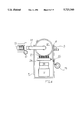
- FIG. 2 is the front view of the agglomeration plant;
- FIG. 3 is the side view of FIG. 2;
- FIG. 4 is the plan view of the plant of FIG. 2;
- FIG. 5 is the side view of the plant of FIG. 2, but with the cover, or cap, raised for the substitution of the bag filters and with the trolley with basket displaced laterally;
- FIGS. 6, 7 illustrate the raising and lowering device of the cap;
- FIG. 1 is a diagram for the implementation of a method of agglomeration for the plant as in Tables 2to 16;
- FIG. 2 is the front view of the agglomeration plant;
- FIG. 3 is the side view of FIG. 2;
- FIG. 4 is the plan view of the plant of FIG. 2;
- FIG. 5 is the side view of the plant of FIG. 2, but with the cover, or cap, raised for the substitution of the bag
- FIGS. 9, 10, 11 are, respectively, the side view of a bag filter with corresponding detachable basket and the plan views of the coupling device for the bag filter, respectively in the coupled and uncoupled positions;
- FIGS. 12, 13 illustrate the lifting device for the basket for the hermetic closure of the bottom end of the agglomeration chamber, respectively, in the raised and lowered positions;
- FIGS. 14, 15 illustrate the basket in the two positions, respectively, horizontal and rotated for emptying;
- FIG. 16 is the side view of the basket rotated 180° for dismounting the fluidizing net;
- FIG. 17 is section XVII--XVII of FIG.
- FIG. 18 is the reflected view of FIG. 17 showing the connection between the flanges making up the said locking device;
- FIGS. 19, 20 show the locked position of FIGS. 17, 18;
- FIG. 21 is an enlarged and partially sectioned detail of the support hinge of the trolley, floating in the vertical direction;
- FIGS. 22, 23, 24 are top views, respectively, of the basket on the trolley, of its guide rails in the structure and of the two together;
- FIG. 25 is the side view of the empty plant, that is, without powder to be agglomerated, showing the flow lines of the air from inlet to outlet;
- FIG. 26 is the simplified, interrupted and partially sectioned side view of the plant in operating conditions;
- FIG. 27 is an enlarged plan view of the basket containing the powder in the configuration of FIG. 16, but in a version with a rapid action locking device for the fluidizing net;
- FIG. 28 is the side view of the basket in FIG. 27, in an inclined position for cleaning or inspecting the fluidizing net;
- FIG. 29 is partial, enlarged and interrupted section XXIX--XXIX of FIG. 27;
- FIG. 30 is section XXX--XXX of FIG. 27;
- FIG. 31 is a view as in FIG. 21, but in the version with the basket as in FIG. 27;
- FIG. 32 is a block diagram of a computer program to implement the method as described in the present invention, in the version with the cleaning phase of the filter units in series;
- FIG. 33 is a block diagram analogous to that of FIG. 32, but with the cleaning phase of the filter units in parallel;
- FIG. 34 is an operational diagram for a plant for agglomerating powders equipped with both programs of the diagrams in FIGS. 32 and
- L, S, respectively, the binding liquid (for example, water and sugar) and the corresponding atomized phase by means of compressed air at pressures ranging from approximately 2 bar to approximately 7 bar;
- P1, C respectively, the powder to be granulated (for example, high density whey proteins) placed in the corresponding container or basket;
- A1, F1, R respectively, the outside air, the filtering station and the heating station;
- G the agglomeration chamber into which flow, respectively, the powder to be agglomerated P1, outside air A1, filtered and heated, atomized binding liquid L;
- A2 the spent air, which, after having heated granulated product P2 in agglomeration chamber G, is filtered in F2 and reintroduced into atmosphere A2; 1, (FIG.
- a bag filter to filter the air exiting granulation chamber G; 35, a cylindrical wire frame support inside the filter bag serving as stiffener; 36, a plastic positioning element to anchor the support, by means of upper diametric traverse 37 of support 35, to support.
- Basket C consists of body 40a, preferably in the shape of a truncated cone, having, at its minor base, flange 41 to which is coupled in a detachable manner, for example, by means of eye bolts 43, external peripheral ring 42 supporting net 21: the eye bolts, or other analogous coupling devices, lock ring 42 of net 21 against flange 41, within corresponding annular seats present in said flange and in said locking ring, by means of detachable locking ring 40.
- Locking ring 40 has a number of spokes 40b to limit the deformation of net 20 with the weight of the material contained in basket C.
- the eye bolts having a screw stem as shown in FIG. 19, can have one end having a hinged coupling with locking ring 40 in peripheral protruding supports 43a, the other end being insertable in corresponding U shaped appendages 43b protruding outwards from flange 41.
- Basket C also has cylindrical appendages 44, protruding outwards, preferably with aligned horizontal axes, to support the basket on horizontal arms 45, parallel with one another, of trolley 22.
- the part of the arms, preferably the ends, that couple with appendages 44 have seats 44a coupled with the external shape of appendages 44, so as to allow the rotation in the seats of the appendages: in the example illustrated in FIG. 21, seats 44a are semi-cylindrical.
- At least one of the appendages 44 has a reference means for setting the angular position of basket C in relation to trolley 22: such reference means can advantageously comprise, simply and effectively, removable locating pin 46 inserted from above in vertical through hole 46a in each appendage 44 and in hole 46b aligned with in corresponding arm 45.
- the means of reference comprise a number of through holes, shown as 46a, 46c, in appendage 44, having coinciding axes and forming between them angle A corresponding to the inclination of basket C when it is positioned with an inclination of approximately 90° to the horizontal for the substitution of the net, as illustrated in FIG. 28; holes 46a, 46b can be positioned in transverse planes that are parallel to each other in order to avoid excessive weakening of appendage 44.
- hole 46b may consist of a slot with a length sufficient to enable the insertion of pin 46 in anyone of holes 46a, 46b.
- the locking ring can be hinged to flange 41 by means of a pair of hinges 50, positioned peripherally on the minor base of the truncated cone body 40a.
- Each hinge 50 consists of a bracket 51 fixed peripherally to locking ring 40, having a central portion that couples with a hooked seat 53 correspondingly located on flange 41 of container C. With such an arrangement it is possible to rapidly remove locking ring 40 from flange 41.
- the figures also show: 47, the positioning guides for trolley 22 with respect to risers 4; V, (FIG. 34) the parameters of the method to be set, in the case of the operational cycle controlled by means of an electronic computer; CM, the application of manual commands; P.L.C.
- PR1 Program Logical Computer
- PR2 two automatic programs, differentiated by two possible different sequences of the same parameters depending on the type of process P
- VP the parameter for the speed of rotation of the pump
- VV the parameter for the speed of rotation of the ventilator
- TP the time interval reserved for cleaning bag filters 25
- TPV the time intervals of operation of pump 28 and ventilator 16; it is to be noted that with program PR2 the cleaning phase is continuous during the agglomeration process.
- Operation is as follows: having filled basket C with the quantity of powder or granules that correspond to a load, air circulation is activated to set up a vacuum in agglomeration chamber G by activating motorized ventilator 16, thereby initiating fluidization, at first executed dry for a period sufficient to heat up the load; then the binding liquid is supplied to the atomizing dispensers by activating peristaltic pump 28 until the desired size of granule is obtained: a complete cycle possibly consisting of a number of iterations of the phases described above, executed with manual commands or automatically, for example, using programs PR1 or PR2.
- the hermetic closure of agglomeration chamber G is achieved by activating cylinders 23 that lift air funnel 20 so that its upper ledge comes into contact with bottom flange 40 of basket C and, continuing upwards, lifting also the basket until its upper rim creates a sealing contact with the lower rim of casing 1 of agglomeration chamber G with perfect centering due to guides 47; lowering cylinders 23 disengages the casing of the chamber to enable the basket to be removed or in preparation for the overturning manoeuvre, after cap 10 has been lifted by activating cylinders 12.
- each floating pin 46 mqy advantageously be still in a position to act as guide when lowering the basket at the end of the granulation cycle. This being achieved by determining a length for each pin that is sufficient to prevent it from being pulled out of hole 46b when basket C is in its uppermost position.
- the central portion of the casing of a silo for storing powdered, or granulate, materials can be rotated in an entirely analogous manner, when it is coupled detachably to a closing cover, raised by means of actuators analogous to cylinders 12, and to a base structure for the extraction of the product, for example consisting of a screw conveyor, vertically coupled to the lower rim of the central portion by means of actuators analogous to cylinders 23.
- T1 time interval for preheating the powder, or granules
- time interval for dispensing the binding liquid defining the duration of the agglomeration phase
- T2' possible time interval of inversion of the flow of binding liquid
- T4 time interval between two successive cleanings of the subgroups of filter elements
- NCP number of cleaning phases of the entire filter unit in a complete cycle
- VIP angular velocity of the supply pump for the binding liquid in the possible phase of inversion of flow of the liquid
- NC number of iterations of the phases that make up a complete cycle
- T time interval for cleaning the entire filter unit.
- control of the air temperature can be made independent of processor PLC, or controlled by it, for example, by defining a further variable to be set using keyboard TAS, interpreted as a threshold value to be reached before commencing the agglomeration phase.
- the method is executed in the succession of phases as follows.
- the body of powder, or granules is preheated for a set time T1, depending on the initial type of product and on the dimensions of the granules, as specified indicatively in the examples given later.
- the flow of binding liquid is activated for a time T2, corresponding to the formation of granules having the required dimensions, prior the possible phase F2' of inversion of flow in the outlet line of the dispenser to prevent it from dripping.
- the third phase F3 then follows, in which the granules are dried for a set time T3, and subsequent repetitions for a number NC of iterations of all the phases F1, F2, F2', F3 or even just some of them, depending on the set sequence.
- phase F extends for the entire duration of the sequence, even partial, of phases F1, F2, F2', F3. It is to be noted that, in this case, cleaning of the subgroups of the filter unit is carried out with a cyclic sequence distributed throughout the extent of each phase, without interruptions.
- processor PLC governs a retroactive control sequence of the vacuum in agglomeration chamber CA.
- a signal proportional to the value of the vacuum measured in chamber CA is sent to PLC and compared with the set variable DP; in the case processor PLC determines that the vacuum greater than the set limit DP, it activates a frequency converter INV to slow down the aspiration unit VEN, thereby reducing the vacuum in chamber CA; in the case of insufficient vacuum, PLC commands an acceleration of the aspiration unit.
- converter INV can activate a servomotor to vary the aspiration flow section upstream of chamber CA.
- the activation of the servomotor can also be directly controlled by processor PLC.
- Ventilator VEN is advantageously located downstream of the agglomeration chamber, so as to be able to achieve the desired vacuum in the agglomeration chamber; moreover, it can also be located upstream of the said chamber, however presenting greater difficulties in the control of the process and of the flow of air.
- Granulometry greater or equal to 60 micrometers
- Binding liquid sugar solution in water with 30% sugar
- Agglomeration chamber inlet air temperature during the first heating phase of the powder 100° C.
- Granulation chamber inlet air temperature during the second phase of agglomeration and the third phase of granulate drying 80° C.
- Binding liquid 3% malto-dextrin and dextrose solution in water
- Agglomeration chamber inlet air temperature during the first heating phase of the powder 90° C.
- the atomization of the binding liquid was obtained with an atomizing nozzle supplied with compressed air at a pressure of 5 bar to obtain liquid particles with an average diameter of 0.1-0.2 mm.
- binding liquid was achieved by means of a peristaltic pump; however, other types of volumetric pumps can be employed, if it is not necessary to avoid contact between the liquid and the components of the pump, for example, for reasons of hygiene.
- a great advantage of the present invention is the possibility of setting agglomeration phases of extended duration (in the examples up to 40 min); this is due to the possibility of executing cleaning phases in backpressure of subgroups of the filter unit with a cyclic sequence, even during the execution of the agglomeration phase.
- the agglomeration cycle of the powder is controlled in function of the air temperatures at the inlet and at the outlet of the granulation chamber as follows:
- the air temperature at the inlet of the chamber is set (set point temperature);
- a critical air temperature at the outlet of the camber is also set, depending on the type of granulate (obtainable by experiment), as well as an air outlet temperature corresponding to the beginning of the atomization of the of the binding liquid (pump start temperature).
- the outlet temperature tends to rise progressively until it reaches the pump start temperature, when the PLC triggers the start of the supply of binding liquid. This causes the progressive cooling of the powder being granulated, with consequent reduction in the air temperature at the outlet of the chamber, until the critical temperature is reached.
- the supply of liquid is interrupted at this point to permit the powder to be heated and dried.
- the supply of the liquid is not interrupted, but the air inlet temperature is increased by an amount corresponding to the difference between the pump start temperature and the air outlet temperature measured after a set time interval.
- the critical temperature is approximately 55° C.
- the pump start temperature is approximately 60° C.
- the initial Set point temperature is 95° C.
- the critical temperature is approximately 50° C.
- the pump start temperature is approximately 55° C.
- the initial set point temperature is 95° C.
- the critical temperature is approximately 37° C.
- the pump start temperature is approximately 40° C.
- the initial set point temperature is 80° C.
- Example 3 the binding liquid consists of a sugar and caramel solution in water, whereas in Example 4 and 5 the binding liquid consists of malto-dextrin solution in water.
- the agglomeration cycle finishes when the pump for the injection of the binding liquid is stopped after a set quantity of liquid has been dispensed.
Landscapes
- Chemical & Material Sciences (AREA)
- Chemical Kinetics & Catalysis (AREA)
- Organic Chemistry (AREA)
- Medical Preparation Storing Or Oral Administration Devices (AREA)
- Glanulating (AREA)
- Fertilizers (AREA)
- Storage Of Fruits Or Vegetables (AREA)
- Drying Of Solid Materials (AREA)
- Physical Or Chemical Processes And Apparatus (AREA)
- Control And Other Processes For Unpacking Of Materials (AREA)
- Centrifugal Separators (AREA)
- Mixers With Rotating Receptacles And Mixers With Vibration Mechanisms (AREA)
Abstract
Description
T=n T5+(n-1) T4
Claims (19)
Applications Claiming Priority (5)
| Application Number | Priority Date | Filing Date | Title |
|---|---|---|---|
| ITMO930055A IT1262609B (en) | 1993-04-20 | 1993-04-20 | Method for the agglomeration of powders or granules, particularly for the food, chemical or pharmaceutical sectors |
| ITMO93A0056 | 1993-04-20 | ||
| ITMO93A0055 | 1993-04-20 | ||
| ITMO930056A IT1262610B (en) | 1993-04-20 | 1993-04-20 | Container for the storage and/or treatment of powder or granular material, particularly for agglomeration equipment in the food, chemical or pharmaceutical industries |
| PCT/EP1994/001219 WO1994023831A1 (en) | 1993-04-20 | 1994-04-19 | Method and device for treating powders or granules |
Publications (1)
| Publication Number | Publication Date |
|---|---|
| US5723160A true US5723160A (en) | 1998-03-03 |
Family
ID=26331723
Family Applications (1)
| Application Number | Title | Priority Date | Filing Date |
|---|---|---|---|
| US08/535,031 Expired - Lifetime US5723160A (en) | 1993-04-20 | 1994-04-19 | Plant for the treatment of powders, or granules, in particular of the food, chemical, or pharmaceutical industries |
Country Status (10)
| Country | Link |
|---|---|
| US (1) | US5723160A (en) |
| EP (1) | EP0695214B1 (en) |
| JP (1) | JP3464222B2 (en) |
| CN (1) | CN1057019C (en) |
| AT (1) | ATE158955T1 (en) |
| AU (1) | AU6720794A (en) |
| DE (1) | DE69406122T2 (en) |
| ES (1) | ES2110752T3 (en) |
| RU (1) | RU2126711C1 (en) |
| WO (1) | WO1994023831A1 (en) |
Cited By (8)
| Publication number | Priority date | Publication date | Assignee | Title |
|---|---|---|---|---|
| WO2001023286A1 (en) * | 1999-09-28 | 2001-04-05 | I.M.A. Industria Macchine Automatiche S.P.A. | A device for controlling movement of skips for treatment of granular or powder and liquid materials |
| US6833149B2 (en) | 1999-01-14 | 2004-12-21 | Cargill, Incorporated | Method and apparatus for processing vegetable oil miscella, method for conditioning a polymeric microfiltration membrane, membrane, and lecithin product |
| US20110155052A1 (en) * | 2008-08-05 | 2011-06-30 | Iwao Fusejima | Fluidized bed apparatus |
| US20110180157A1 (en) * | 2008-08-05 | 2011-07-28 | Iwao Fusejima | Fluidized bed apparatus |
| US9346633B2 (en) * | 2012-06-11 | 2016-05-24 | Babcock Power Services, Inc. | Fluidization and alignment elbow |
| US20170115060A1 (en) * | 2015-10-15 | 2017-04-27 | Jimmyash Llc | Method and apparatus for the controlled conveyance of a workpiece through a fluidized bed dryer |
| US20180148198A1 (en) * | 2015-05-26 | 2018-05-31 | Wacker Chemie Ag | Packaging of polysilicon |
| US20180238543A1 (en) * | 2017-02-23 | 2018-08-23 | Kappes, Cassiday & Associates | Sand bed downdraft furnace and activated carbon scrubber |
Families Citing this family (7)
| Publication number | Priority date | Publication date | Assignee | Title |
|---|---|---|---|---|
| US7244401B1 (en) | 1998-11-13 | 2007-07-17 | Ir Systems International | Apparatus for separation of constituents from matrices |
| US6125552A (en) * | 1998-12-17 | 2000-10-03 | Genencor International, Inc. | Side discharge assembly for a fluid bed processing system and method thereof |
| DE10323089B4 (en) * | 2003-05-16 | 2006-12-07 | Glatt Process Technology Gmbh | Fluidized bed device |
| JP4741545B2 (en) * | 2007-04-19 | 2011-08-03 | 新日本製鐵株式会社 | Fluidized bed drying classifier |
| JP5386165B2 (en) * | 2008-12-19 | 2014-01-15 | 三立機器株式会社 | Dust collector |
| JP5363889B2 (en) * | 2009-06-25 | 2013-12-11 | フロイント産業株式会社 | Fluidized bed equipment |
| KR102174768B1 (en) * | 2020-07-22 | 2020-11-05 | 주식회사 피티케이 | Tilting Type Powder Container for Tablet |
Citations (3)
| Publication number | Priority date | Publication date | Assignee | Title |
|---|---|---|---|---|
| US4027624A (en) * | 1974-09-20 | 1977-06-07 | Freund Industrial Co., Ltd. | Fluid granulating/coating apparatus utilizing suction air current |
| US4797271A (en) * | 1987-02-19 | 1989-01-10 | Aluminum Company Of America | Producing alumina granules in a fluidized bed |
| US4832700A (en) * | 1982-01-09 | 1989-05-23 | Sandoz Ltd. | Process and apparatus for preparing dust-free granular material |
Family Cites Families (4)
| Publication number | Priority date | Publication date | Assignee | Title |
|---|---|---|---|---|
| US4027626A (en) * | 1975-06-12 | 1977-06-07 | Desousa Peter | Pet elevator |
| JPS5239580A (en) * | 1975-09-25 | 1977-03-26 | Sankyo Co Ltd | Method of grain making for fluidizing bed |
| EP0282514B1 (en) * | 1986-09-09 | 1990-04-18 | Pharmatronic AG | Process and device for agglomerating and/or coating particles |
| US4723971A (en) * | 1986-10-21 | 1988-02-09 | Caldas Ladislau B | Industrial vacuum cleaner |
-
1994
- 1994-04-19 US US08/535,031 patent/US5723160A/en not_active Expired - Lifetime
- 1994-04-19 RU RU95120087A patent/RU2126711C1/en not_active IP Right Cessation
- 1994-04-19 EP EP94915525A patent/EP0695214B1/en not_active Expired - Lifetime
- 1994-04-19 DE DE69406122T patent/DE69406122T2/en not_active Expired - Lifetime
- 1994-04-19 JP JP52277894A patent/JP3464222B2/en not_active Expired - Fee Related
- 1994-04-19 CN CN94191837A patent/CN1057019C/en not_active Expired - Fee Related
- 1994-04-19 AT AT94915525T patent/ATE158955T1/en active
- 1994-04-19 AU AU67207/94A patent/AU6720794A/en not_active Abandoned
- 1994-04-19 WO PCT/EP1994/001219 patent/WO1994023831A1/en active IP Right Grant
- 1994-04-19 ES ES94915525T patent/ES2110752T3/en not_active Expired - Lifetime
Patent Citations (3)
| Publication number | Priority date | Publication date | Assignee | Title |
|---|---|---|---|---|
| US4027624A (en) * | 1974-09-20 | 1977-06-07 | Freund Industrial Co., Ltd. | Fluid granulating/coating apparatus utilizing suction air current |
| US4832700A (en) * | 1982-01-09 | 1989-05-23 | Sandoz Ltd. | Process and apparatus for preparing dust-free granular material |
| US4797271A (en) * | 1987-02-19 | 1989-01-10 | Aluminum Company Of America | Producing alumina granules in a fluidized bed |
Cited By (15)
| Publication number | Priority date | Publication date | Assignee | Title |
|---|---|---|---|---|
| US7923052B2 (en) | 1999-01-14 | 2011-04-12 | Cargill, Incorporated | Method and apparatus for processing vegetable oil miscella, method for conditioning a polymeric microfiltration membrane, membrane, and lecithin product |
| US6833149B2 (en) | 1999-01-14 | 2004-12-21 | Cargill, Incorporated | Method and apparatus for processing vegetable oil miscella, method for conditioning a polymeric microfiltration membrane, membrane, and lecithin product |
| US20050118313A1 (en) * | 1999-01-14 | 2005-06-02 | Cargill, Incorporated | Method and apparatus for processing vegetable oil miscella, method for conditioning a polymeric microfiltration membrane, membrane, and lecithin product |
| US7494679B2 (en) | 1999-01-14 | 2009-02-24 | Cargill Incorporated | Method and apparatus for processing vegetable oil miscella, method for conditioning a polymeric microfiltration membrane, membrane, and lecithin product |
| US20100018922A1 (en) * | 1999-01-14 | 2010-01-28 | Cargill, Incorporated | Method and apparatus for processing vegetable oil miscella, method for conditioning a polymeric microfiltration membrane, membrane, and lecithin product |
| WO2001023286A1 (en) * | 1999-09-28 | 2001-04-05 | I.M.A. Industria Macchine Automatiche S.P.A. | A device for controlling movement of skips for treatment of granular or powder and liquid materials |
| US6702543B1 (en) | 1999-09-28 | 2004-03-09 | I.M.A. Industria Macchine Automatiche S.P.A. | Device for controlling movement of skips for treatment of granular or powder and liquid materials |
| US20110180157A1 (en) * | 2008-08-05 | 2011-07-28 | Iwao Fusejima | Fluidized bed apparatus |
| US20110155052A1 (en) * | 2008-08-05 | 2011-06-30 | Iwao Fusejima | Fluidized bed apparatus |
| US9346633B2 (en) * | 2012-06-11 | 2016-05-24 | Babcock Power Services, Inc. | Fluidization and alignment elbow |
| US20180148198A1 (en) * | 2015-05-26 | 2018-05-31 | Wacker Chemie Ag | Packaging of polysilicon |
| US10689135B2 (en) * | 2015-05-26 | 2020-06-23 | Wacker Chemie Ag | Method of packaging of polysilicon |
| US20170115060A1 (en) * | 2015-10-15 | 2017-04-27 | Jimmyash Llc | Method and apparatus for the controlled conveyance of a workpiece through a fluidized bed dryer |
| US11118835B2 (en) * | 2015-10-15 | 2021-09-14 | Jimmyash Llc | Method and apparatus for the controlled conveyance of a workpiece through a fluidized bed dryer |
| US20180238543A1 (en) * | 2017-02-23 | 2018-08-23 | Kappes, Cassiday & Associates | Sand bed downdraft furnace and activated carbon scrubber |
Also Published As
| Publication number | Publication date |
|---|---|
| EP0695214B1 (en) | 1997-10-08 |
| AU6720794A (en) | 1994-11-08 |
| ATE158955T1 (en) | 1997-10-15 |
| ES2110752T3 (en) | 1998-02-16 |
| DE69406122T2 (en) | 1998-04-09 |
| RU2126711C1 (en) | 1999-02-27 |
| JPH08508931A (en) | 1996-09-24 |
| DE69406122D1 (en) | 1997-11-13 |
| JP3464222B2 (en) | 2003-11-05 |
| CN1121319A (en) | 1996-04-24 |
| EP0695214A1 (en) | 1996-02-07 |
| WO1994023831A1 (en) | 1994-10-27 |
| CN1057019C (en) | 2000-10-04 |
Similar Documents
| Publication | Publication Date | Title |
|---|---|---|
| US5723160A (en) | Plant for the treatment of powders, or granules, in particular of the food, chemical, or pharmaceutical industries | |
| US4685809A (en) | Fluidized bed apparatus | |
| US4639383A (en) | Method and apparatus for coating particulate granules | |
| US9788566B2 (en) | Process for drying and powderizing functional foods, nutraceuticals, and natural health ingredients | |
| US3237596A (en) | Apparatus for coating discrete solids | |
| DE2508164A1 (en) | DEVICE FOR PREPARING STERILIZED SOLID MATERIAL | |
| CN102712427B (en) | For equipment and the method for vacuum handling powder-product or analogue | |
| US11612831B2 (en) | Device and method for the high-pressure treatment of bulk material by extraction and/or impregnation and use | |
| CN105564936A (en) | Self-cleaning feed discharge conveying device | |
| US7922798B2 (en) | Granulator device | |
| US3411480A (en) | Device for coating fine solids | |
| JPH08510953A (en) | Countercurrent diffusion extraction device | |
| JP2676416B2 (en) | Fluidized bed equipment for powder granulation | |
| US4439072A (en) | Fluidized bed discharge bin with aerating blower | |
| GB2268094A (en) | Filter for a gas stream, especially from a fluidised bed | |
| KR102047632B1 (en) | Equipments and method for manufacturing chicken sauce with improved hygiene, quality maintenance and storage stability | |
| FR2759304A1 (en) | Fluidised bed and operation thereof | |
| JP7492533B2 (en) | Method for discharging an apparatus for the production of granular or extrudate materials - Patents.com | |
| CN107261986A (en) | A kind of fluid bed vertical discharging apparatus | |
| CN219072712U (en) | Anti-caking powdery seasoning discharging device | |
| NL9000081A (en) | VAT FOR TREATING A PARTICULAR MATERIAL WITH A FLUID. | |
| CN219790765U (en) | Device for introducing food into a container | |
| US4560282A (en) | Apparatus for mixing and granulating powdery substances with a sifting device attached by means of a valve closure | |
| WO1995001829A1 (en) | Apparatus and method for dissolving solids | |
| JPS63318945A (en) | Apparatus for washing fluidized bed apparatus |
Legal Events
| Date | Code | Title | Description |
|---|---|---|---|
| AS | Assignment |
Owner name: ICO OLEODINAMICI S.P.A., ITALY Free format text: ASSIGNMENT OF ASSIGNORS INTEREST;ASSIGNORS:NORA, ANDREA;BARANI, RUGGERO;REEL/FRAME:008791/0213 Effective date: 19971025 |
|
| FEPP | Fee payment procedure |
Free format text: PAYOR NUMBER ASSIGNED (ORIGINAL EVENT CODE: ASPN); ENTITY STATUS OF PATENT OWNER: LARGE ENTITY |
|
| STCF | Information on status: patent grant |
Free format text: PATENTED CASE |
|
| FPAY | Fee payment |
Year of fee payment: 4 |
|
| FEPP | Fee payment procedure |
Free format text: PAT HOLDER NO LONGER CLAIMS SMALL ENTITY STATUS, ENTITY STATUS SET TO UNDISCOUNTED (ORIGINAL EVENT CODE: STOL); ENTITY STATUS OF PATENT OWNER: LARGE ENTITY |
|
| AS | Assignment |
Owner name: I.M.A. INDUSTRIA MACCHINE AUTOMATICHE S.P.A., ITAL Free format text: ASSIGNMENT OF ASSIGNORS INTEREST;ASSIGNOR:ICO OLEODINAMICI S.P.A.;REEL/FRAME:012875/0642 Effective date: 20020222 |
|
| FEPP | Fee payment procedure |
Free format text: PAYER NUMBER DE-ASSIGNED (ORIGINAL EVENT CODE: RMPN); ENTITY STATUS OF PATENT OWNER: LARGE ENTITY |
|
| FPAY | Fee payment |
Year of fee payment: 8 |
|
| FEPP | Fee payment procedure |
Free format text: PAYOR NUMBER ASSIGNED (ORIGINAL EVENT CODE: ASPN); ENTITY STATUS OF PATENT OWNER: LARGE ENTITY |
|
| FPAY | Fee payment |
Year of fee payment: 12 |