US571908A - scribnee - Google Patents
scribnee Download PDFInfo
- Publication number
- US571908A US571908A US571908DA US571908A US 571908 A US571908 A US 571908A US 571908D A US571908D A US 571908DA US 571908 A US571908 A US 571908A
- Authority
- US
- United States
- Prior art keywords
- mercury
- tube
- air
- valve
- branch
- Prior art date
- Legal status (The legal status is an assumption and is not a legal conclusion. Google has not performed a legal analysis and makes no representation as to the accuracy of the status listed.)
- Expired - Lifetime
Links
- QSHDDOUJBYECFT-UHFFFAOYSA-N mercury Chemical compound [Hg] QSHDDOUJBYECFT-UHFFFAOYSA-N 0.000 description 27
- 229910052753 mercury Inorganic materials 0.000 description 27
- 239000012530 fluid Substances 0.000 description 4
- 239000007788 liquid Substances 0.000 description 4
- 230000006378 damage Effects 0.000 description 3
- 208000027418 Wounds and injury Diseases 0.000 description 2
- 238000010276 construction Methods 0.000 description 2
- 208000014674 injury Diseases 0.000 description 2
- 230000002159 abnormal effect Effects 0.000 description 1
- 238000002485 combustion reaction Methods 0.000 description 1
- 238000000034 method Methods 0.000 description 1
- 238000007789 sealing Methods 0.000 description 1
- 239000000126 substance Substances 0.000 description 1
- 210000001364 upper extremity Anatomy 0.000 description 1
Images

Classifications
-
- F—MECHANICAL ENGINEERING; LIGHTING; HEATING; WEAPONS; BLASTING
- F04—POSITIVE - DISPLACEMENT MACHINES FOR LIQUIDS; PUMPS FOR LIQUIDS OR ELASTIC FLUIDS
- F04B—POSITIVE-DISPLACEMENT MACHINES FOR LIQUIDS; PUMPS
- F04B39/00—Component parts, details, or accessories, of pumps or pumping systems specially adapted for elastic fluids, not otherwise provided for in, or of interest apart from, groups F04B25/00 - F04B37/00
- F04B39/0005—Component parts, details, or accessories, of pumps or pumping systems specially adapted for elastic fluids, not otherwise provided for in, or of interest apart from, groups F04B25/00 - F04B37/00 adaptations of pistons
- F04B39/0011—Component parts, details, or accessories, of pumps or pumping systems specially adapted for elastic fluids, not otherwise provided for in, or of interest apart from, groups F04B25/00 - F04B37/00 adaptations of pistons liquid pistons
Definitions
- the pump operates in the usual manner; that is, the air being exhausted by the mechanical pump Ct from the tube 1), and hence from the chamber g, the cock 9 is turned to close the opening between the tube 1) and the branch 0, while the passage f is at the same time opened, admitting the air to the mercury vessel cl.
- the mercury up through the tube h (which, it will be seen, extends nearly to the bottom of the vessel (1,) so as to fill the chamber g, a portion of the mercury passing above the valves h 7L2 into the enlarged portion h of the tube containing said valves.
- the mercury is at the same time forced into the branch k, with which branch k the lamps, as 7.; k &c., to be exhausted are connected, the usual valve Z being provided in the upper portion of the branch
- the mercury having been thus forced into the chamber g, on again closing the cock 2 will descend, the chamber g being sealed above by the action of the mercury which had been forced through the tube h above the valves 71. 72.
- the chamber 9 is repeatedly exhausted. If now one of the lamps, as It, should break, the air rushing in would be liable to cause great injury to the pump or other lamps if there were no means of checking its flow.
- My invention consists of an automatic check or safety valve designed to guard against injury from such accidents. It will be best understood by reference to Fig. 2, in which I have shown two such valves, one in each of the tubes leading to the lamps lo k
- the tube on is provided with two U -shaped bends m m and at the center or upper portion of The pressure of the air forces the double U thus formed there is provided a by-path m about the bend m.
- a seal of mercury as shown, and in the portion of the bend m farthest from the bend m is placed a valve an.
- each separate branch with which a lamp or lamps are connected is provided with a safetyvalve.
- a safetyvalve Ordinarily while the process of exhaustion is going on the mercury seal in the bend m and the valve m will be in the position shown and the outlet for the rarefied air will be through the by-path m around the mercury seal. This by-path m should be small as compared with the main branch m.
- I will designate the open spaces above the mercury seal which are connected through the by-path m as chambers. During the passage of gas through the device there will obviously be a difference of pressure in the two chambers tending to produce a flow of the gas.
- the action of the mercury is of course determined by the amount of diiference in pressure in the fluid in the two chambers. If therefore a bulb, as bulb k, breaks, the air rushing in will force the mercury in whole or in part out of the bend on into bend m and the valve m will be tightly closed and the rush of air will be stopped. This is done so quickly that no damage can result to any of the parts of the apparatus, and although the other lamps, as lamp k may be burning their filaments will not be burned out, since the branch m is sealed almost at the very instant that the bulb 76 is broken.
- the pipe m provided with bends m m the by-path 012 about a liquid seal contained in the bend m, in combination with a valve m whereby when air rushes into the tube m the liquid sealing substance is caused to immediately close the valve, substantially as specified.
- the combination with a tube connect ing two chambers containing a fluid at difl'erent pressures, of a column of mercury or other liquid in the tube, a valve adapted to be closed upon its seat by the action of the mercury when surrounded by it, and a restricted passage or by-path about the column of mercury, whereby the mercury column is driven forward to close the valve by an abnormal difference in pressure of the fluid in the chambers, substantially as specified.
Landscapes
- Engineering & Computer Science (AREA)
- Mechanical Engineering (AREA)
- General Engineering & Computer Science (AREA)
- Vessels And Coating Films For Discharge Lamps (AREA)
Description
(No Model.) 2 Sheets-Sheet 1.
O. E. SGRIBNER. SAFETY VALVE FOR MERGURIAL AIR PUMPS.
No. 571,908. Patented Nov. 24, 1896.
j w v 6 I fl p j 713: I M i In! f h I 1 Z We H a Q W 6 a/ barzes or; nez' 2 Sheefs-Shet 2.
(in Model.)
G. E. SORIBNER. .SAPETY VALVE FOR MERGURIAL AIR PUMPS.
No. 571,908. Patented No'v. 2451896,
131716727707: QWZQSE scnzfi/ar".
(NE uomus mar-vs cu, wo-Lrruu. WASHINGTON, n. c.
UNITED STATES PATENT OFFICE.
CHARLES E. SCRIBNER, OF CHICAGO, ILLINOIS, ASSIGNOR TO THE WESTERN ELECTRIC COMPANY, OF SAME PLACE.
SAFETY-VALVE FOR MERCURIAL AIR-PUMPS.
SPECIFICATION forming part of Letters Patent No. 571,908, dated November 24, 1896.
Application filed June 13, 1893. Serial No. 477,476. (No model.)
To all whom/it may concern.-.
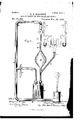
Be it known that 1, CHARLES E. SORIBNER, a citizen of the United States, residing at Chicago, in the county of Cook and State of Illinois, have invented a certain new and useful Improvement in Safety-Valves for Air- Pumps, (Case No. 338,) of which the following is a full, clear, concise,ancl exact descripstood by reference to the accompanying drawings, in which- Figure 1 is a side elevation illustrative of an air-pump for exhausting incandescent lamps with my invention applied thereto. Fig. 2 is a detailed view in section showing the manner of arranging the safety-valves in the branches from the pump, upon which branchesthe lamps which are to be exhausted are mounted in the usual manner.
Like parts are indicated by similar letters of reference throughout the different figures.
I will first briefly describe the action of the pump. An ordinary mechanical pump a is connected with the tube Z). This pump a is kept in action during the time the work of exhausting the bulbs is going on. The tube Z) is connected through the branch 0 with a vessel d, which contains mercury. In this branch 0 is placed a three-waycock e, which when in the position shown leaves a passage from tube Z) into the branch 0 and vessel d, while the passage f to the external air is closed. The vertical tube h, enlarged near its middle portion to form the exhaustingchamber g, dips into the mercury vessel (1 at its lower end and is connected at its upper extremity with an upward extension of the tube 1). The usual valves h and Its are provided above the chamber g in the tube h, and an enlargement h is formed in the tube above the valves to receive the mercury and prevent its ejection into the tube b.
The pump operates in the usual manner; that is, the air being exhausted by the mechanical pump Ct from the tube 1), and hence from the chamber g, the cock 9 is turned to close the opening between the tube 1) and the branch 0, while the passage f is at the same time opened, admitting the air to the mercury vessel cl. the mercury up through the tube h, (which, it will be seen, extends nearly to the bottom of the vessel (1,) so as to fill the chamber g, a portion of the mercury passing above the valves h 7L2 into the enlarged portion h of the tube containing said valves. It will also be understood that the mercury is at the same time forced into the branch k, with which branch k the lamps, as 7.; k &c., to be exhausted are connected, the usual valve Z being provided in the upper portion of the branch The mercury having been thus forced into the chamber g, on again closing the cock 2 will descend, the chamber g being sealed above by the action of the mercury which had been forced through the tube h above the valves 71. 72. Thus the chamber 9 is repeatedly exhausted. If now one of the lamps, as It, should break, the air rushing in would be liable to cause great injury to the pump or other lamps if there were no means of checking its flow. If the mercury stood in the chamber 9 when such breakage occurred, it would be thrown violently against the top of the chamber and through the valves IL2 71'' and would probably break the chamber. At the same time the admission of air to the passage would cause the combustion of the filaments in other lamps connected therewith if they were lighted.
My invention consists of an automatic check or safety valve designed to guard against injury from such accidents. It will be best understood by reference to Fig. 2, in which I have shown two such valves, one in each of the tubes leading to the lamps lo k The tube on is provided with two U -shaped bends m m and at the center or upper portion of The pressure of the air forces the double U thus formed there is provided a by-path m about the bend m. In this bend on is placed a seal of mercury, as shown, and in the portion of the bend m farthest from the bend m is placed a valve an. In the branch leading to the lamp 1 0 a similar safety-valve is also placed that is, speaking generally, each separate branch with which a lamp or lamps are connected is provided with a safetyvalve. Ordinarily while the process of exhaustion is going on the mercury seal in the bend m and the valve m will be in the position shown and the outlet for the rarefied air will be through the by-path m around the mercury seal. This by-path m should be small as compared with the main branch m. For convenience I will designate the open spaces above the mercury seal which are connected through the by-path m as chambers. During the passage of gas through the device there will obviously be a difference of pressure in the two chambers tending to produce a flow of the gas. The action of the mercury is of course determined by the amount of diiference in pressure in the fluid in the two chambers. If therefore a bulb, as bulb k, breaks, the air rushing in will force the mercury in whole or in part out of the bend on into bend m and the valve m will be tightly closed and the rush of air will be stopped. This is done so quickly that no damage can result to any of the parts of the apparatus, and although the other lamps, as lamp k may be burning their filaments will not be burned out, since the branch m is sealed almost at the very instant that the bulb 76 is broken.
It is evident that my invention might be advantageously employed Whenever it is desired to provide for checking automatically the sudden rush of any gas through a pipe. I therefore do not limit myself to the use of my invention in connectionv with incandescent-lamp-exhausting apparatus nor to the details of construction herein shown, since it is obvious that they may be varied indefinitely by those skilled in mechanical construction.
Having thus described my invention, I
claim asnew and desire to secure by Letters Patent- 7 1. The combination with a pipe connected with an air-pump and leading to a bulb to be exhausted, of two U-shaped bends in said pipe, one of said bends containing a mercury seal and the other a valve, and a by-path of comparatively small capacity leading around the mercury, whereby when air is admitted suddenly the mercury is transferred by the pressure of the air to the portion of the pipe containing the Valve to close the same, substantially as and for the purpose specified.
2. The pipe m provided with bends m m the by-path 012 about a liquid seal contained in the bend m, in combination with a valve m whereby when air rushes into the tube m the liquid sealing substance is caused to immediately close the valve, substantially as specified.
3. The combination with a tube connect ing two chambers containing a fluid at difl'erent pressures, of a column of mercury or other liquid in the tube, a valve adapted to be closed upon its seat by the action of the mercury when surrounded by it, and a restricted passage or by-path about the column of mercury, whereby the mercury column is driven forward to close the valve by an abnormal difference in pressure of the fluid in the chambers, substantially as specified.
4. The combination with two chambers con-' taining a fluid at different pressures, of a tube connecting the chambers, a column of mercury or other liquid in the tube, means for retaining the mercury column normally in a stable position in the tube, a normally open valve in the tube adapted to be closed by the action of the mercury column when thrown against it, and a restricted passage or by-path about the mercury column when in its normal position, substantially as described.
In witness whereof I hereunto subscribe my name this 2d day of June, A. D. 1893.
CHARLES E. SORIBNER. \Vitnesses:
ELLA EDLER, LUCILE RUssELL.
Publications (1)
| Publication Number | Publication Date |
|---|---|
| US571908A true US571908A (en) | 1896-11-24 |
Family
ID=2640607
Family Applications (1)
| Application Number | Title | Priority Date | Filing Date |
|---|---|---|---|
| US571908D Expired - Lifetime US571908A (en) | scribnee |
Country Status (1)
| Country | Link |
|---|---|
| US (1) | US571908A (en) |
-
0
- US US571908D patent/US571908A/en not_active Expired - Lifetime
Similar Documents
| Publication | Publication Date | Title |
|---|---|---|
| JP2019521296A5 (en) | ||
| US571908A (en) | scribnee | |
| US350761A (en) | Elijah neff | |
| US773316A (en) | Rotary pump. | |
| US1171610A (en) | Automatic valve. | |
| US1003946A (en) | Pneumatic water-elevator. | |
| US491543A (en) | Valve for pumps | |
| US47530A (en) | Improvement in oil-pumps | |
| US533226A (en) | Liquid-raising apparatus | |
| US990085A (en) | Subterranean pumping system. | |
| US916366A (en) | Ejector for oil-wells. | |
| US1292851A (en) | Liquid-elevating apparatus. | |
| US288030A (en) | peters | |
| US1003592A (en) | Means for automatically draining pumps. | |
| US748727A (en) | Oil-supply system | |
| US1286970A (en) | Hydraulically-operated oil-storage tank. | |
| US641409A (en) | Air-pump. | |
| US215723A (en) | Improvement in jet-exhausters for gas-works | |
| US940366A (en) | Filling apparatus for liquids. | |
| US1074934A (en) | System of storing and conveying inflammable and other liquids. | |
| US294210A (en) | Self and w | |
| US678009A (en) | Pump. | |
| US547162A (en) | Lift and force pump | |
| US1045157A (en) | Automatic chemical air-lift. | |
| US123859A (en) | Improvement in apparatus for filling and emptying oil-tanks |