US288030A - peters - Google Patents
peters Download PDFInfo
- Publication number
- US288030A US288030A US288030DA US288030A US 288030 A US288030 A US 288030A US 288030D A US288030D A US 288030DA US 288030 A US288030 A US 288030A
- Authority
- US
- United States
- Prior art keywords
- valve
- pump
- lift
- force
- discharge
- Prior art date
- Legal status (The legal status is an assumption and is not a legal conclusion. Google has not performed a legal analysis and makes no representation as to the accuracy of the status listed.)
- Expired - Lifetime
Links
- 238000005266 casting Methods 0.000 description 11
- XEEYBQQBJWHFJM-UHFFFAOYSA-N Iron Chemical compound [Fe] XEEYBQQBJWHFJM-UHFFFAOYSA-N 0.000 description 6
- 238000010276 construction Methods 0.000 description 4
- 239000002184 metal Substances 0.000 description 4
- 229910052751 metal Inorganic materials 0.000 description 4
- NJPPVKZQTLUDBO-UHFFFAOYSA-N novaluron Chemical compound C1=C(Cl)C(OC(F)(F)C(OC(F)(F)F)F)=CC=C1NC(=O)NC(=O)C1=C(F)C=CC=C1F NJPPVKZQTLUDBO-UHFFFAOYSA-N 0.000 description 4
- XLYOFNOQVPJJNP-UHFFFAOYSA-N water Substances O XLYOFNOQVPJJNP-UHFFFAOYSA-N 0.000 description 4
- 229910052742 iron Inorganic materials 0.000 description 3
- 241000309551 Arthraxon hispidus Species 0.000 description 2
- NRUQNUIWEUZVLI-UHFFFAOYSA-O diethanolammonium nitrate Chemical compound [O-][N+]([O-])=O.OCC[NH2+]CCO NRUQNUIWEUZVLI-UHFFFAOYSA-O 0.000 description 2
- 241000239290 Araneae Species 0.000 description 1
- 229910001369 Brass Inorganic materials 0.000 description 1
- 230000006978 adaptation Effects 0.000 description 1
- 239000010951 brass Substances 0.000 description 1
- 230000007797 corrosion Effects 0.000 description 1
- 238000005260 corrosion Methods 0.000 description 1
- 230000008878 coupling Effects 0.000 description 1
- 238000010168 coupling process Methods 0.000 description 1
- 238000005859 coupling reaction Methods 0.000 description 1
- 230000000694 effects Effects 0.000 description 1
- 238000012856 packing Methods 0.000 description 1
- 239000007787 solid Substances 0.000 description 1
Images

Classifications
-
- B—PERFORMING OPERATIONS; TRANSPORTING
- B65—CONVEYING; PACKING; STORING; HANDLING THIN OR FILAMENTARY MATERIAL
- B65B—MACHINES, APPARATUS OR DEVICES FOR, OR METHODS OF, PACKAGING ARTICLES OR MATERIALS; UNPACKING
- B65B31/00—Packaging articles or materials under special atmospheric or gaseous conditions; Adding propellants to aerosol containers
- B65B31/04—Evacuating, pressurising or gasifying filled containers or wrappers by means of nozzles through which air or other gas, e.g. an inert gas, is withdrawn or supplied
- B65B31/046—Evacuating, pressurising or gasifying filled containers or wrappers by means of nozzles through which air or other gas, e.g. an inert gas, is withdrawn or supplied the nozzles co-operating, or being combined, with a device for opening or closing the container or wrapper
- B65B31/047—Evacuating, pressurising or gasifying filled containers or wrappers by means of nozzles through which air or other gas, e.g. an inert gas, is withdrawn or supplied the nozzles co-operating, or being combined, with a device for opening or closing the container or wrapper the nozzles co-operating with a check valve in the opening of the container or wrapper
-
- F—MECHANICAL ENGINEERING; LIGHTING; HEATING; WEAPONS; BLASTING
- F04—POSITIVE - DISPLACEMENT MACHINES FOR LIQUIDS; PUMPS FOR LIQUIDS OR ELASTIC FLUIDS
- F04B—POSITIVE-DISPLACEMENT MACHINES FOR LIQUIDS; PUMPS
- F04B33/00—Pumps actuated by muscle power, e.g. for inflating
Definitions
- My improvement relates to what is known as IO the pitcher or common iron lift pump
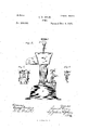
- Figure 1 represents a vertical central section of a lift-pump embracing my improvements; Fig. 2, a similar sectional view, showing the air-chamber formed in the base-casting of the Fig. 4, a detail View of the handle-joint head, and Fig. 5 a detail view of the clamping device for the hose attachment.
- the lift-valve G is carried by a metal stock or seat, H, provided with a suitable packing, a, and a metal yoke-housing, I, for the valve, which is' preferably of winged or spider form and of metal.
- the force attachment which I have combined-with this pump consists of an improved construction for closing the lift-valve upon its seat, for maintaining a direct well-supported central force upon said valve, and of an airchamber connected with the foree-discharge.
- This operating-tube forms the guide andsupport for an adjustable stoprod, d, which is screw-threaded at itslower end, and is screwed into the cross-bar e of the yoke or housing for the valve, which housing-yoke forms the nut for the screw-rod.
- This adjustable stop-rod is preferably of brass,to prevent corrosion, and passes through the joint-head c, and is provided with a hand-wheel, f, by 0 which it is screwed up and down, to bring its lower end down upon the top of the metal valve, and thereby close it upon the seat or box, as shown, to convert the lift into a force pump.
- the valve-closing device gives the important advantage of a direct central stop or hold upon the valve, and thereby insures an equal pressure of the valve upon its seat, and provides for properly supporting the stop-rod at the point of pressure, and at the upper outside operating end, which is thereby brought within convenient position for being turned to raise and to lower the screw-rod.
- the direct central support given by the screwrod is of vital importance, since there is no lateral strain upon rod and no side strain upon the valve. .
- the joint-pin g for the handle passes through the j oint-head c, and the screwrod passesthrough a hole in said joint-pin,
- this air-chamber is mounted upon a-separate flat-chambered casting, t, which is fastened upon the top of the pedestal, and the pump-cylinder is fastened by the same screw-bolts upon the top of said fiat-chambered casting, there being a through opening in said chambered casting corresponding with the pump-cylinder. Over this through opening the foot-valve is secured or placed upon the top of the pedestal.
- the chambered casting projects to one side of the pump-cylinder, and the force-discharge valve 3 5 j is fastened to its upper side and opens within the air-chamber, the valve-opening forming thereby the communication of the pumpcylinder with the force-discharge 7a, which also communicates with the air-chamber.
- This latter communication must be with the bottom of the air-chamber, and for this purpose the force-discharge extends by a pipe, Z, down into and opens near the bottom of said air-chamber.
- the force-discharge opening it is formed so as to receive a coupling, an, attached to the end of the hose.
- the airchamber and its force-dischar e can be applied to the iron lift-pump now in use, in which case the flat-chambered casting is secured by the screw-bolts passing through the which it opens.
Landscapes
- Engineering & Computer Science (AREA)
- Mechanical Engineering (AREA)
- Chemical & Material Sciences (AREA)
- Dispersion Chemistry (AREA)
- General Engineering & Computer Science (AREA)
- Reciprocating Pumps (AREA)
- Compressors, Vaccum Pumps And Other Relevant Systems (AREA)
Description
2 Sheets-Sheet I.
(No Model.)
0. S. DEAN.
PUMP.
Patented NOV. 6, 1883.
N. PETERQ Phulwmho n hur. walhinglum n.c.
(No' odel. 2 SheetsSheet 2.
- G. S. DEAN.
PUMB.
No. 288,030. Patented Nov. 6, 18 83.
um HIIHIIIIIIII I Y mum! If UNTTED STATES CYRUS S. DEAN,
PATENT Trice.
OF FORT ERIE, ONTARIO, ASSIGNOR TO EDIVIN MORRIS,
OF OOIVLAND, ONTARIO, CANADA.
PUMP.
SPECIFICATION forming part of Letters Patent No. 288,030, dated November 6, 1883.
Application filed February 10,1833. (Xo model.) I
To aZZ whom it may concern.-
Be it known that I, OYRUs SUMNER DEAN, a subject of the Queen of Great Britain and Ireland, residing at Fort Erie, in the county of Welland, Province of Ontario, in the Dominion of Canada, have invented new and usew/ ful Improvements in Pumps, of which the following is a specification.
My improvement relates to what is known as IO the pitcher or common iron lift pump,
and particularly to such pump constructed with a force attachment, whereby to produce a con yertible force and lift pump.
' The objects of my improvements are to reu- 1 der such force attachment more effective, dur-- able, and convenient for use, and to provide for a continuous and steady stream of water in using the convertible force attachment in the common pitcher-pump.
An important matter of my improvement is the adaptation of the force attachment to the pitcher-pump, whereby the latter as now eonstructcdcan be easily provided with the force attachment, using the ordinary lift-valve and its box or seat. The convertibility of the pump consists in the employment of means for closing the valve upon its seat, and of maintaining it in such closed position, and in this it is important that the force be exerted upon the valve in a direct central line, so as to hold the valve closed with an equal and tight bearing upon its seat against the great pressure of the water in the descending movement of the valve. It is also of great importance that the means for supporting the valve under its pressure should be itself properly supported and arranged, with convenient outside means for operating it to convert the pump from a lift to a force; and it is to these. particulars 0 that my improvements are directed, in connection with an air-chamber through and by which a steady forceflow of the water is effected.
Referring to the accompanying drawings, 5 Figure 1 represents a vertical central section of a lift-pump embracing my improvements; Fig. 2, a similar sectional view, showing the air-chamber formed in the base-casting of the Fig. 4, a detail View of the handle-joint head, and Fig. 5 a detail view of the clamping device for the hose attachment.
The pump=cylinder Ahas the usual open pitcher top, B, and .liftdischarge O, and is mounted upon a base casting or pedestal, D, for the foot-valve E, and the pipe F, leading into the well or cistern, as shown; or itmay be of any suitable construction; but the eonstruction shown is preferable, because it is the common iron lift-pump generally in use. In such pump the lift-valve G is carried by a metal stock or seat, H, provided with a suitable packing, a, and a metal yoke-housing, I, for the valve, which is' preferably of winged or spider form and of metal. These parts, with the foot-valve E,.which may be of the ordinary flap kind, form the common liftpump.
The force attachment which I have combined-with this pump consists of an improved construction for closing the lift-valve upon its seat, for maintaining a direct well-supported central force upon said valve, and of an airchamber connected with the foree-discharge.
Instead of the solid rod for connecting and operating the box of the lift-valve, I use a tube,
1), which may be a piece of gas-pipe screwed into the yoke or housing I for the lift-valve, and, passingthrough the open top of thepumpcylinder,is screwed into a j oint-head,c, to which the pump-handle (not shown) is jointed in any suitable manner. This operating-tube forms the guide andsupport for an adjustable stoprod, d, which is screw-threaded at itslower end, and is screwed into the cross-bar e of the yoke or housing for the valve, which housing-yoke forms the nut for the screw-rod. This adjustable stop-rod is preferably of brass,to prevent corrosion, and passes through the joint-head c, and is provided with a hand-wheel, f, by 0 which it is screwed up and down, to bring its lower end down upon the top of the metal valve, and thereby close it upon the seat or box, as shown, to convert the lift into a force pump. Raisingthescrew-rodleavesthe valve 5 free to rise and fall, as in the ordinary lift pump. This construction and arrangement of pump; Fig. 3, a side elevation of the same;
the valve-closing device gives the important advantage of a direct central stop or hold upon the valve, and thereby insures an equal pressure of the valve upon its seat, and provides for properly supporting the stop-rod at the point of pressure, and at the upper outside operating end, which is thereby brought within convenient position for being turned to raise and to lower the screw-rod. As thepressure upon the valve is'very great when it is closed, the direct central support given by the screwrod is of vital importance, since there is no lateral strain upon rod and no side strain upon the valve. .The joint-pin g for the handle passes through the j oint-head c, and the screwrod passesthrough a hole in said joint-pin,
, and thus secures it in place without riveting or screw-nut fastening. I
To effect a steady and continuous flow of the water, I combine an airchamber, 7a, with the force-discharge opening, and a valve arranged between the lower end of the pumpcylinder and the communication with said airchamber. As shown in Fig. 1, this air-chamber is mounted upon a-separate flat-chambered casting, t, which is fastened upon the top of the pedestal, and the pump-cylinder is fastened by the same screw-bolts upon the top of said fiat-chambered casting, there being a through opening in said chambered casting corresponding with the pump-cylinder. Over this through opening the foot-valve is secured or placed upon the top of the pedestal. The chambered casting projects to one side of the pump-cylinder, and the force-discharge valve 3 5 j is fastened to its upper side and opens within the air-chamber, the valve-opening forming thereby the communication of the pumpcylinder with the force-discharge 7a, which also communicates with the air-chamber. This latter communication must be with the bottom of the air-chamber, and for this purpose the force-discharge extends by a pipe, Z, down into and opens near the bottom of said air-chamber. The force-discharge opening it is formed so as to receive a coupling, an, attached to the end of the hose.
Provision is made for the easy and quick attachment of the hose to the force-discharge by a clamping device consisting of a handwheel screw, it, supported centrally over the force-discharge by screw-bolts a" r, fastened in lugs s s in the fixed castings, and connected at .their upper ends by a cross-bar, t, through a screw-threaded opening, in which the clamping hand-wheel screw it passes, so as to be screwed down upon a boss, 12, on the hosecoupling, to bind it upon the nozzle of the force-discharge. By this construction the airchamber and its force-dischar e can be applied to the iron lift-pump now in use, in which case the flat-chambered casting is secured by the screw-bolts passing through the which it opens.
usual lugs on the bottom of the pump-cylinder and the top of the pedestal. When the air-chamber is formed within and by the pedestal-casting, as shown in Figs. 2 and 3, the flat-chambered casting is formed upon its top, and the force-discharge pipel is cast upon the side of said air-chamber, into the bottom of I do not claim, broadly, a lift-pump pro-- vided witha force-discharge, and means for producing a convertible force and lift pump in whichthe lift-valve of the piston is provided with an adj ustable stop adapted to close the piston-valve to produce aforce-discharge.
I claim V I. The combination, in "a pump-cylinder having a lift-discharge and a force-discharge,
of the lift and the foot valves with the open valve-seat yoke I, a tubular operating connection, b, for said valve-yoke, and a screw-rod, d, passing through a nut, e, in said valve-yoke and through said tubular connection, and prolift-discharge and a force-discharge, of the lift and the foot valves, and means, substantially such as described, whereby the lift-valve may be-closed upon its seat, withan air-chamber, it, having avalved communication, j, with the lower end of the pump-cylinder, substantially as described, for the purpose-specified.
3. The combination, in a pump, of the lift and foot valves, the tubular operating-connection b'for the lift-valve seat, the screw-rod d, for closing said lift-valve, passing through said tubular operating-connection, the fiat-chambered casting i,.the air-chamber h, the forcedischarge tube opening therein, and the valved communication j with said air-chamber, sub-.'
stantially as described, for the purpose specified.
4. The combination, in a convertible lift and force pump, of the tubular operating-connection I) for the lift-valve with the screw-rod d, for closing the lift-valve upon its seat, passing through a nut, e, in the lift-valve yoke, and through the joint-head c and joint-pin g for the operating pump handle, and provided with a hand-wheel, f, outside of said joint-connection, substantially as described, for the purpose specified. I
In testimony whereof I have hereunto set my hand in, the presence of two subscribing witnesses.
' CYRUS S. DEAN.
Publications (1)
| Publication Number | Publication Date |
|---|---|
| US288030A true US288030A (en) | 1883-11-06 |
Family
ID=2357224
Family Applications (1)
| Application Number | Title | Priority Date | Filing Date |
|---|---|---|---|
| US288030D Expired - Lifetime US288030A (en) | peters |
Country Status (1)
| Country | Link |
|---|---|
| US (1) | US288030A (en) |
Cited By (2)
| Publication number | Priority date | Publication date | Assignee | Title |
|---|---|---|---|---|
| US3941518A (en) * | 1973-05-25 | 1976-03-02 | Scm Corporation | Steam-spray iron |
| US4915600A (en) * | 1988-10-12 | 1990-04-10 | Hutchinson Research And Development Corp. | Rotary apparatus with rotating mobile and stationary blocking members |
-
0
- US US288030D patent/US288030A/en not_active Expired - Lifetime
Cited By (2)
| Publication number | Priority date | Publication date | Assignee | Title |
|---|---|---|---|---|
| US3941518A (en) * | 1973-05-25 | 1976-03-02 | Scm Corporation | Steam-spray iron |
| US4915600A (en) * | 1988-10-12 | 1990-04-10 | Hutchinson Research And Development Corp. | Rotary apparatus with rotating mobile and stationary blocking members |
Similar Documents
| Publication | Publication Date | Title |
|---|---|---|
| US403507A (en) | Petek j | |
| US288030A (en) | peters | |
| US350761A (en) | Elijah neff | |
| US856215A (en) | Pump. | |
| US1389907A (en) | Water-inlet valve for tanks | |
| US679454A (en) | Pump. | |
| US542766A (en) | Interchangeable pump | |
| US255966A (en) | Moses gayjian | |
| US482588A (en) | William peterson | |
| US177667A (en) | Improvement in pumps | |
| US580745A (en) | Third to lot le bow | |
| US534988A (en) | Stand-pipe for locomotives | |
| USRE10048E (en) | myees | |
| US271829A (en) | Hamline q | |
| US329234A (en) | Non-freezing force-pump | |
| US822178A (en) | Pump. | |
| US265691A (en) | miller | |
| US486350A (en) | myers | |
| US216693A (en) | Improvement in governors for pumping-engines | |
| US289288A (en) | William s | |
| US204958A (en) | Improvement in pumps | |
| US625023A (en) | Joseoph a | |
| US450719A (en) | Regulator | |
| US512611A (en) | Albina e | |
| US520466A (en) | Edward h |