US571268A - iieene - Google Patents
iieene Download PDFInfo
- Publication number
- US571268A US571268A US571268DA US571268A US 571268 A US571268 A US 571268A US 571268D A US571268D A US 571268DA US 571268 A US571268 A US 571268A
- Authority
- US
- United States
- Prior art keywords
- shaft
- barrel
- cylinder
- key
- arm
- Prior art date
- Legal status (The legal status is an assumption and is not a legal conclusion. Google has not performed a legal analysis and makes no representation as to the accuracy of the status listed.)
- Expired - Lifetime
Links
Images
Classifications
-
- B—PERFORMING OPERATIONS; TRANSPORTING
- B41—PRINTING; LINING MACHINES; TYPEWRITERS; STAMPS
- B41J—TYPEWRITERS; SELECTIVE PRINTING MECHANISMS, i.e. MECHANISMS PRINTING OTHERWISE THAN FROM A FORME; CORRECTION OF TYPOGRAPHICAL ERRORS
- B41J2/00—Typewriters or selective printing mechanisms characterised by the printing or marking process for which they are designed
- B41J2/005—Typewriters or selective printing mechanisms characterised by the printing or marking process for which they are designed characterised by bringing liquid or particles selectively into contact with a printing material
- B41J2/01—Ink jet
- B41J2/015—Ink jet characterised by the jet generation process
- B41J2/04—Ink jet characterised by the jet generation process generating single droplets or particles on demand
-
- B—PERFORMING OPERATIONS; TRANSPORTING
- B43—WRITING OR DRAWING IMPLEMENTS; BUREAU ACCESSORIES
- B43L—ARTICLES FOR WRITING OR DRAWING UPON; WRITING OR DRAWING AIDS; ACCESSORIES FOR WRITING OR DRAWING
- B43L13/00—Drawing instruments, or writing or drawing appliances or accessories not otherwise provided for
- B43L13/02—Draughting machines or drawing devices for keeping parallelism
- B43L13/022—Draughting machines or drawing devices for keeping parallelism automatic
- B43L13/024—Drawing heads therefor
Definitions
- My invention relates to improvements in keys, and more especially to a key employed in actuating the mechanism in a time-recording machine.
- One object of my invention is to provide a key whose shank is not liable to be bent or mutilated from much or severe usage.
- Another object of my invention is to provide a key comprising not only a shaft or spindle having a laterally-projecting tongue or arm adapted to engage and operate mechanism in a lock or machine, but also a cylinder or barrel surrounding and aifording bearing for the shank and slotted laterally and circumferentially to accommodate the operation of the tongue or arm of the inclosed shaft.
- Another object is to provide the cylinder or barrel with a tongue or arm adapted to engage mechanism in the lock or machine, so that the cylinder or barrel, when the tongue on the shank or stem of the key has been actuated as far as the size of the slot in the cylinder or barrel will accommodate, will be turned with the shaft upon turning the latter still farther in the same direction, and thereby cause the tongue upon the cylinder orbarrel to perform its function.
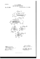
- Figure l is a side elevation of a key embodying my invention.
- Fig. 2 is a side elevation of the key and shows the cylinder or barrel of the key in central longitudinal section.
- Fig. 3 is a transverse section on line 3 3, Fig. 2.
- Fig. t is a transverse section on line a et, Fig. 2.
- Fig. 5 is a transverse section of a key that not only has a laterally and outwardly projecting tongue or arm upon the shaft or inner portion of the key, but also has another tongue or arm formed upon the cylinder or barrel that affords bearing for said shaft.
- My improved key comprises a hollow cylinder or barrel A, made of any suitable metal or material.
- a shaft l has suitable bearing within and is arranged longitudinally of the cylinder or barrel A.
- a handle or th u nib-andfinger piece l is rigid with one end of stem or shaft B, and a tongue or arm ZJ' projects laterally and outwardly from shaft l through a lateral slot a in cylinder or barrel A and is adapted to engage and operate the mechanism of a lock or machine for the purpose of obtaining certain results, and the sine of slot a, cireuinferentially of cylinder or barrel A, is large enough to accommodate the turning of shaft B t-he required distance.
- One, a, of the side walls of slots d constitutes a stop for for limiting the movement of member B in one direction
- the oppositely-located side wall ai of the slot forms a stop for limiting the movement of said member B in the opposite direction
- wall a2 in the case illustrated constitutes a stop for the movement of member B in the direction required to cause the tongue or arm of said member to perform its function.
- slot a is formed at the outer end of cylinder or barrel A, and the latter at its opposite end and externally has a beveled or flat surface A', that, upon the introduction of the key into the lock or machine in connection with which the key is adapted to be used, is designed to engage the under side of a member within said lock or machine, and thereby hold the cylinder or barrel stationary while accommodating the turning of shaft B within the cylinder or barrel without effecting a rotation of the latter.
- cylinder or barrel A would be provided externally, in any approved manner, with a distinguishing type C, that would be preferably formed upon a thin metallic plate or piece C, suitably secured to a flattened surface A2 formed upon any suitable portion of the cylinder or barrel.
- the diameter of the handle-bearing end of shaft B is preferably such that said portion of the shaft nicely lits within the surrounding cylinder or barrel, and the remaining portion of the shaft is sufficiently smaller in diameter to accommodate the provision of a torsional spiral spring D, confined upon the reduced portion of the shaft between the shoulder ll', formed at the inner end of the diainetrically larger portion of the shaft, and an annular shoulder or flange A3, formed internally of cylinder or barrel A. Opposite ends of spring D are suitably secured to said annular shoulder A3 and the aforesaid shaft, respectively, to retain the laterally-projeeting tongue or arm of the shaft in its starting or normal position.
- the end wall af of slot a constitutes a stop for preventing endwise displacement of the shaft in the one direction, and a washer or other member ll, thatis suitably secured upon the shaft at the outer side of the internal flange of the cylinder or barrel, prevents cndwise displacement of the shaft in the opposite direction.
- Tongue or arm l/ and shaft ll are preferably com posed of separate pieces, and said member b is preferably secured within a slot b2 with which the shaft is provided, and the handle or thumb-and-linger piece for turning the shaft is preferably integral with member h.
- l would also remark that, if desired, cylinder or barrel A may be provided at any suitable point externally with a tongue or arm Al, (see Fig.
- Tongue or arm A4 it is obvious, might be used in the actuation of mechanism within the lock or machine during the introduction of the key, or the laterally-projecting tongue or arm L of shaft B might be employed not only to operate mechanism within the lock or machine for performing its ordinary function, but might also be employed for moving or actuating other mechanism instrumental lin rcmoving the member engaged by the beveled or flattened surface A of the key out of the way, and thereby render cylinder or barrel A free to be turned, in which ease it is obvious that upon turning the shaftof the key in the direction required to cause the outwardlyprojecting tongue or arm of the shaft to perform its function, the surrounding cylinder or barrel would, upon the further actuation of the shaft in the same direction, be turned with the shaft, because if said cylinder or barrel were free to turn, member b' of the shaft and wall a2 of the slot in the cylinder or barrel would establish operative connection between the
- a key comprising a laterally and circumferentially slotted cylinder or barrel bearing the distinguishing-type externally; a shaft having bearing within the cylinder or barrel. and fixed in the latter so far as endwise movenient is concerned, said shaft being provided with a tongue or arm projecting laterally and outwardly through the slot in the cylinder or barrel, and means for turning the shaft, substantially as set forth.
- a key consisting of a laterally and circumferentially slotted type-bearing cylinder or barrel A; a shaft having bearin g in the cylinder or barrel and fixed in the latter so far as endwise movement is concerned, said shaft being provided with a laterally-projecting arm extending through the slot in the barrel; means for turning the shaft, and a spiral. spring confined upon the shaft within the barreland having opposite ends secured to the barrel and shaft, respectively, and acting to retain the shaft in its normal position, substantially as set forth.
- a key consisting of a type-bearing cylinder or barrel slotted laterally at its forward end and provided with an internal flange at or near the rear end; a shaft having suitable bea-rin g in the cylinder or barrel and provided with an arm projecting laterally through the slot in the barrel and next forward of the rear wall of said slot, said shaft extending through the aforesaid flange; a member fixed upon the shaft next rearward of said flange and overlapping the flanges rear side, and means at the forward end of the shaft for turning the latter, substantially as set forth.
- a key consisting of a cylinder or barrel slotted laterally at its forward end, and provided, at its rear end and externally, with a flattened surface A', a shaft having suitable bearing in said. barrel and provided with an arm extending through the slot in the barrel, and means for turning the shaft, substantially as set forth.
- a key consisting of a laterally-slotted cylinder or barrel provided, at any suitable point externally, with a laterally-prejecting arm, a shaft having suitable bearing in the barrel and provided with a laterally-projecting arm extending through the slot in the barrel, and means for turning the shaft, substantially as set forth.
- a key consisting of a cylinder or barrel slotted laterally at its forward end, and provided, upon one side and at or near its -rear end and externally, with a distinguishingtype, a shaft having bearing in ⁇ said barrel and provided with an arm extending through IOO IIO
Landscapes
- Engineering & Computer Science (AREA)
- Automation & Control Theory (AREA)
- Lock And Its Accessories (AREA)
Description
l(No Model.)
E. G. HERNE.
KEY FOR TIME REGORDERS.
No. 571,268. Patented Nov. l0, 1896.
19.521 er? fol? UNITED STATES PATENT OEEIoE.
.EDIVARD Cr. IIEENE, OF CLEVELAND, OIIIO, ASSIGNOR TO GEORGE IV. IIEENE, OF SAME PLACE.
KEY FOR TIME-RECORDERS.
SPECIFICATION forming part of Letters Patent No. 571,268, dated November 10, 1896.
Application filed Ap1i16,l896.
.To all whom, it may concern.-
Be it known that I, EDWARD G. IIEENE, of Cleveland, Cuyahoga county, Chio, have invented certain new and useful Improvements in Keys; and I do hereby declare the following to be a full, clear, and exact description of the invention, such as will enable others skilled in the art to which it pertains to make and use the same.
My invention relates to improvements in keys, and more especially to a key employed in actuating the mechanism in a time-recording machine.
One object of my invention is to provide a key whose shank is not liable to be bent or mutilated from much or severe usage.
Another object of my invention is to provide a key comprising not only a shaft or spindle having a laterally-projecting tongue or arm adapted to engage and operate mechanism in a lock or machine, but also a cylinder or barrel surrounding and aifording bearing for the shank and slotted laterally and circumferentially to accommodate the operation of the tongue or arm of the inclosed shaft.
Another object is to provide the cylinder or barrel with a tongue or arm adapted to engage mechanism in the lock or machine, so that the cylinder or barrel, when the tongue on the shank or stem of the key has been actuated as far as the size of the slot in the cylinder or barrel will accommodate, will be turned with the shaft upon turning the latter still farther in the same direction, and thereby cause the tongue upon the cylinder orbarrel to perform its function.
IVith these objects in view, and to the end of attaining certain other advantages hereinafter referred to, my invention consists in certain features of construction and combinations of parts hereinafter described, and pointed out in the claims.
In the accompanying drawings, Figure l is a side elevation of a key embodying my invention. Fig. 2 is a side elevation of the key and shows the cylinder or barrel of the key in central longitudinal section. Fig. 3 is a transverse section on line 3 3, Fig. 2.
serial No. 586,352. oa mornin Fig. t is a transverse section on line a et, Fig. 2. Fig. 5 is a transverse section of a key that not only has a laterally and outwardly projecting tongue or arm upon the shaft or inner portion of the key, but also has another tongue or arm formed upon the cylinder or barrel that affords bearing for said shaft.
My improved key comprises a hollow cylinder or barrel A, made of any suitable metal or material. A shaft l; has suitable bearing within and is arranged longitudinally of the cylinder or barrel A. A handle or th u nib-andfinger piece l; is rigid with one end of stem or shaft B, and a tongue or arm ZJ' projects laterally and outwardly from shaft l through a lateral slot a in cylinder or barrel A and is adapted to engage and operate the mechanism of a lock or machine for the purpose of obtaining certain results, and the sine of slot a, cireuinferentially of cylinder or barrel A, is large enough to accommodate the turning of shaft B t-he required distance. One, a, of the side walls of slots d constitutes a stop for for limiting the movement of member B in one direction, andthe oppositely-located side wall ai of the slot forms a stop for limiting the movement of said member B in the opposite direction, and wall a2 in the case illustrated constitutes a stop for the movement of member B in the direction required to cause the tongue or arm of said member to perform its function.
In the case illustrated slot a is formed at the outer end of cylinder or barrel A, and the latter at its opposite end and externally has a beveled or flat surface A', that, upon the introduction of the key into the lock or machine in connection with which the key is adapted to be used, is designed to engage the under side of a member within said lock or machine, and thereby hold the cylinder or barrel stationary while accommodating the turning of shaft B within the cylinder or barrel without effecting a rotation of the latter.
If the key is designed for use ina time-recording machine, cylinder or barrel A would be provided externally, in any approved manner, with a distinguishing type C, that would be preferably formed upon a thin metallic plate or piece C, suitably secured to a flattened surface A2 formed upon any suitable portion of the cylinder or barrel.
The diameter of the handle-bearing end of shaft B is preferably such that said portion of the shaft nicely lits within the surrounding cylinder or barrel, and the remaining portion of the shaft is sufficiently smaller in diameter to accommodate the provision of a torsional spiral spring D, confined upon the reduced portion of the shaft between the shoulder ll', formed at the inner end of the diainetrically larger portion of the shaft, and an annular shoulder or flange A3, formed internally of cylinder or barrel A. Opposite ends of spring D are suitably secured to said annular shoulder A3 and the aforesaid shaft, respectively, to retain the laterally-projeeting tongue or arm of the shaft in its starting or normal position.
The end wall af of slot a constitutes a stop for preventing endwise displacement of the shaft in the one direction, and a washer or other member ll, thatis suitably secured upon the shaft at the outer side of the internal flange of the cylinder or barrel, prevents cndwise displacement of the shaft in the opposite direction. Tongue or arm l/ and shaft ll are preferably com posed of separate pieces, and said member b is preferably secured within a slot b2 with which the shaft is provided, and the handle or thumb-and-linger piece for turning the shaft is preferably integral with member h. l would also remark that, if desired, cylinder or barrel A may be provided at any suitable point externally with a tongue or arm Al, (see Fig. 5,) adapted to engage and operate mechanism within the lock or machine in connection with which the key is designed to be used. Tongue or arm A4, it is obvious, might be used in the actuation of mechanism within the lock or machine during the introduction of the key, or the laterally-projecting tongue or arm L of shaft B might be employed not only to operate mechanism within the lock or machine for performing its ordinary function, but might also be employed for moving or actuating other mechanism instrumental lin rcmoving the member engaged by the beveled or flattened surface A of the key out of the way, and thereby render cylinder or barrel A free to be turned, in which ease it is obvious that upon turning the shaftof the key in the direction required to cause the outwardlyprojecting tongue or arm of the shaft to perform its function, the surrounding cylinder or barrel would, upon the further actuation of the shaft in the same direction, be turned with the shaft, because if said cylinder or barrel were free to turn, member b' of the shaft and wall a2 of the slot in the cylinder or barrel would establish operative connection between the shaft and cylinder or barrel upon the actuation of said member t' into engagement with the aforesaid wall of the slot, and
sarees hence it will be observed that by means of my improved key certain mechanism in the lock or machine could be operated by the tongue or arm of the inner portion or core (shaft ll) of the key and other mechanism in the lock or machine operated by a tongue or arm on the cylinder or barrel.
l. A key comprising a laterally and circumferentially slotted cylinder or barrel bearing the distinguishing-type externally; a shaft having bearing within the cylinder or barrel. and fixed in the latter so far as endwise movenient is concerned, said shaft being provided with a tongue or arm projecting laterally and outwardly through the slot in the cylinder or barrel, and means for turning the shaft, substantially as set forth.
2. A key consisting of a laterally and circumferentially slotted type-bearing cylinder or barrel A; a shaft having bearin g in the cylinder or barrel and fixed in the latter so far as endwise movement is concerned, said shaft being provided with a laterally-projecting arm extending through the slot in the barrel; means for turning the shaft, and a spiral. spring confined upon the shaft within the barreland having opposite ends secured to the barrel and shaft, respectively, and acting to retain the shaft in its normal position, substantially as set forth.
3. A key consisting of a type-bearing cylinder or barrel slotted laterally at its forward end and provided with an internal flange at or near the rear end; a shaft having suitable bea-rin g in the cylinder or barrel and provided with an arm projecting laterally through the slot in the barrel and next forward of the rear wall of said slot, said shaft extending through the aforesaid flange; a member fixed upon the shaft next rearward of said flange and overlapping the flanges rear side, and means at the forward end of the shaft for turning the latter, substantially as set forth.
1t. A key consisting of a cylinder or barrel slotted laterally at its forward end, and provided, at its rear end and externally, with a flattened surface A', a shaft having suitable bearing in said. barrel and provided with an arm extending through the slot in the barrel, and means for turning the shaft, substantially as set forth.
5. A key consisting of a laterally-slotted cylinder or barrel provided, at any suitable point externally, with a laterally-prejecting arm, a shaft having suitable bearing in the barrel and provided with a laterally-projecting arm extending through the slot in the barrel, and means for turning the shaft, substantially as set forth.
G. A key consisting of a cylinder or barrel slotted laterally at its forward end, and provided, upon one side and at or near its -rear end and externally, with a distinguishingtype, a shaft having bearing in `said barrel and provided with an arm extending through IOO IIO
the slot in the barrel7 and means for turning the shaft, substantially as set forth.
A key Consisting of a cylinder or barrel slotted laterally at its forward end, and provided, at or near its rear end and externally with two flattened surfaces A/ and A2; the distinguishing-type formed upon or ixed to one of said flattened surfaces; a shaft having` suitable hearing in said barrel, and means for turning the shaft, substantially as set ro forth.
In testimony whereof I sign this specioation, in the presence of two Witnesses, this 2d day of April, 1896.
EDXVARD G. HEENE.
Witnesses C. lil. DORER, ELLA E. TILDEN.
Publications (1)
| Publication Number | Publication Date |
|---|---|
| US571268A true US571268A (en) | 1896-11-10 |
Family
ID=2639967
Family Applications (1)
| Application Number | Title | Priority Date | Filing Date |
|---|---|---|---|
| US571268D Expired - Lifetime US571268A (en) | iieene |
Country Status (1)
| Country | Link |
|---|---|
| US (1) | US571268A (en) |
-
0
- US US571268D patent/US571268A/en not_active Expired - Lifetime
Similar Documents
| Publication | Publication Date | Title |
|---|---|---|
| US666512A (en) | Ratchet-tool. | |
| US999209A (en) | Ejector for firearms. | |
| US1045935A (en) | Reamer-holder. | |
| US616303A (en) | taylor | |
| US89197A (en) | Edward w | |
| US512980A (en) | Permutation-padlock | |
| US579596A (en) | Pencil-case | |
| US1008734A (en) | Ice-pick. | |
| US504026A (en) | Car-fare holder | |
| US890242A (en) | Calipers. | |
| US880870A (en) | Ratchet mechanism. | |
| US623984A (en) | Handcuff | |
| US610675A (en) | Eric herman ericson | |
| US1069271A (en) | Marking-tally. | |
| US200757A (en) | Improvement in ratchet bit-braces | |
| US467260A (en) | Watch-case pendant | |
| US29432A (en) | Pen and pencil case | |
| US125475A (en) | Improvement in combination locks | |
| US292298A (en) | Screw-driver | |
| US988376A (en) | Chuck. | |
| US1161151A (en) | Combination lock-key. | |
| US562950A (en) | File-box | |
| US1009818A (en) | Fishing-reel. | |
| US937934A (en) | Magazine-lock for take-down repeating shotguns and rifles. | |
| US659368A (en) | Truing-gage. |