US5708665A - Digital receiver using equalization and block decoding with erasure and error correction - Google Patents
Digital receiver using equalization and block decoding with erasure and error correction Download PDFInfo
- Publication number
- US5708665A US5708665A US08/701,710 US70171096A US5708665A US 5708665 A US5708665 A US 5708665A US 70171096 A US70171096 A US 70171096A US 5708665 A US5708665 A US 5708665A
- Authority
- US
- United States
- Prior art keywords
- error
- digital signal
- coded digital
- decoder
- signal
- Prior art date
- Legal status (The legal status is an assumption and is not a legal conclusion. Google has not performed a legal analysis and makes no representation as to the accuracy of the status listed.)
- Expired - Lifetime
Links
Images


Classifications
-
- H—ELECTRICITY
- H04—ELECTRIC COMMUNICATION TECHNIQUE
- H04L—TRANSMISSION OF DIGITAL INFORMATION, e.g. TELEGRAPHIC COMMUNICATION
- H04L1/00—Arrangements for detecting or preventing errors in the information received
- H04L1/004—Arrangements for detecting or preventing errors in the information received by using forward error control
- H04L1/0056—Systems characterized by the type of code used
- H04L1/0057—Block codes
-
- H—ELECTRICITY
- H04—ELECTRIC COMMUNICATION TECHNIQUE
- H04L—TRANSMISSION OF DIGITAL INFORMATION, e.g. TELEGRAPHIC COMMUNICATION
- H04L1/00—Arrangements for detecting or preventing errors in the information received
- H04L1/004—Arrangements for detecting or preventing errors in the information received by using forward error control
- H04L1/0045—Arrangements at the receiver end
-
- H—ELECTRICITY
- H04—ELECTRIC COMMUNICATION TECHNIQUE
- H04L—TRANSMISSION OF DIGITAL INFORMATION, e.g. TELEGRAPHIC COMMUNICATION
- H04L1/00—Arrangements for detecting or preventing errors in the information received
- H04L1/004—Arrangements for detecting or preventing errors in the information received by using forward error control
- H04L1/0056—Systems characterized by the type of code used
- H04L1/0064—Concatenated codes
- H04L1/0065—Serial concatenated codes
-
- H—ELECTRICITY
- H04—ELECTRIC COMMUNICATION TECHNIQUE
- H04L—TRANSMISSION OF DIGITAL INFORMATION, e.g. TELEGRAPHIC COMMUNICATION
- H04L1/00—Arrangements for detecting or preventing errors in the information received
- H04L1/20—Arrangements for detecting or preventing errors in the information received using signal quality detector
- H04L1/208—Arrangements for detecting or preventing errors in the information received using signal quality detector involving signal re-encoding
Definitions
- This invention relates to the field of digital communication systems such as those that might be used for satellite transmission channels and cable channels, and in particular to the decoding of error correction coded signals.
- Error control codes function by accepting input data symbols and processing them in such a way as to add some redundancy to the symbol sequence. All error control codes can be formulated so that this coding process takes the form of adding check symbols to the data symbol sequence. With this formulation, the encoder accepts an input word of k data symbols at each time step and produces a code word with n symbols, k of which are the input data symbols, and n-k of which are the check symbols. An example of such a code word 10 having k data symbols 12 and n-k check symbols 14 is shown in FIG. 1. The redundancy added by the check symbols serves to increase the distance between valid code symbol sequences. A common measure of the distance between code words is the number of symbols in which they differ, defined herein as the Hamming distance.
- FIG. 2 Shown in FIG. 2 are two code words 16 and 18 which are selected from the set of valid code words that make up an example block code.
- a comparison of two code words 16 and 18, shown in FIG. 2 reveals three symbol positions which differ: D 3 , D 5 , and D 7 .
- the Hamming distance between code words 16 and 18 is three.
- the minimum Hamming distance between any two sequences of code words is called the minimum Hamming distance of the code, and is often denoted d min H .
- d min H the minimum Hamming distance between any two code words.
- n E is the number of erasures and n e is the number of errors.
- code word 18 is transmitted and received as a corrupted code word 20 with two symbol errors.
- the received code word is compared to all valid code words, and the valid code word that is most like the received code word is chosen as the correct code word. Decoding is then accomplished by simply removing the check symbols from the chosen code word.
- code word 20 represents a received code word that contains two symbol errors. According to the equation, code word 20 may be incorrectly decoded, and indeed it differs by only one symbol from code word 16. According to the stated decoding algorithm, incorrect code word 16 is chosen, resulting in a decoding error.
- code word 22 when the knowledge of the error locations is applied as shown by code word 22, then these symbols are ignored in the comparison process and code word 22 matches the correct code word 18. Consequently code word 22 with erasures is correctly decoded. In general, the number of erasures that a code can tolerate without making decision errors is twice the number of unerased errors that it can tolerate. Further details on the design and function of error correction codes may be found in Bernard Sklar, Digital Communications: Fundamentals and Applications, Prentice Hall, Englewood Cliffs N.J., pp. 263-365, 1988, incorporated herein by reference.
- Reed-Solomon codes are extremely popular because this family of codes is based on a construction that allows for custom tailoring of the information rate and Hamming distance properties of the code. Furthermore, efficient decoders are easy to design for these codes. However at large block lengths, the performance of Reed-Solomon codes suffers a loss of efficiency.
- a technique for extending the effective block length of these codes is to follow the Reed-Solomon encoder with an interleaver which acts to intersperse the symbols from one code word with the symbols from other code words. This is typically done by writing the code words into a memory matrix column-wise and reading the completed matrix row-wise.
- the interleaver can then be followed by a convolutional encoder which further adds redundancy to the symbol sequence.
- a convolutional encoder which further adds redundancy to the symbol sequence.
- the process is reversed, first applying a convolutional decoder to the received sequence, next applying a de-interleaver, and finally performing the Reed-Solomon block decode.
- Each of the additional steps adds only a moderate amount of complexity to the system while significantly boosting its performance.
- burst errors are not random isolated errors, but rather burst errors are defined as errors which occur in localized groups.
- the nature of the errors on the channel is typically random, although when a concatenated decoder is used, errors in convolutional decoding tend to be burst errors.
- a method for detecting bursts errors of the convolutional decoder would prove advantageous in assisting the following block decoder.
- Other effects may corrupt the transmitted signal. These effects are more bursty in nature (examples: microwave radiation close to the receiving antenna, lightning, home appliance electrical noise, etc.).
- the de-interleaver acts to distribute errors within a group so that they are isolated and fewer occur within a given code word. This in turn enhances the probability that the number of errors will not exceed the correction capability of the Reed-Solomon code. Nevertheless, it is still necessary to use Reed-Solomon codes of moderate length and complexity to keep the error correction capability high enough to preserve their resistance to burst errors.
- the bandwidth available to the data symbols can be decreased to make room for the check symbols, or additional bandwidth can be allocated for the check symbols.
- the first option results in a reduction of the rate at which data can be transmitted
- the second option results in an increase in overall channel bandwidth.
- one of these options is required, but the tradeoff is increased manufacturing tolerances, increased margin for equipment degradation, a reduction of the required signal-to-noise ratio, and an overall reduced probability of error.
- a transmission system having a transmission channel interposed between a concatenated encoder and concatenated decoder.
- the concatenated encoder has an outer block encoder followed by an interleaver followed by an inner convolutional encoder.
- the concatenated decoder has an inner convolutional decoder followed by a deinterleaver followed by a outer block decoder.
- the burst error detection mechanism takes the form of a circuit which re-encodes the output of the inner decoder, compares it with the received sequence of code symbols, and flags a portion of the inner decoder output for erasure when a number of code symbol errors are detected in a given interval.
- a transmission system having a transmission channel interposed between an encoder and a decoder.
- the burst error detection mechanism takes the form of a circuit which equalizes the signal, makes decisions based on the signal, forms a sequence of differences between the equalized signal and the decisions, and flags a portion of the decoder input signal for erasure when the estimated noise level meets one or more criteria in a given interval.
- the present invention contemplates a digital communications system.
- the digital communications system comprises an encoder configured to receive a digital signal representing data for transmission.
- the encoder serves to convert the digital signal to a coded digital signal.
- the coded digital signal may then be sent through a transmission channel.
- An error detector is coupled to the receiving end of the transmission channel to receive the coded digital signal.
- the error detector determines errors in defined locations in the coded digital signal and sets a flag for those defined locations.
- a decoder is coupled to the receiving end of the transmission channel to receive the coded digital signal.
- the decoder is also coupled to receive output from the error detector indicative of the flag status. The decoder then decodes the coded digital sequence using the error location flags to increase its error correcting capability.
- the decoder takes the form of a concatenated decoder in which the output of the inner decoder is coupled as a second input to the error detector, and the outer decoder is coupled to receive output from the error detector indicative of the flag status.
- the outer decoder then decodes the coded digital sequence using the error location flags to increase its error correcting capability.
- the error detector flags errors on the basis of estimated noise levels.
- the decoder is coupled to receive output from the error detector indicative of the flag status. The decoder then decodes the coded digital sequence using the error location flags to increase its error correcting capability.
- FIG. 1 is a code word comprising a structured sequence of data symbols and check symbols encoded according to a block and/or convolutional encoder
- FIG. 2 is set of code words exemplifying a correct code word, an incorrect yet valid code word, a corrupted version of the correct code word with errors, and a corrupted version of the correct code word with erasures;
- FIG. 3 is a block diagram of a digital communications system having a concatenated encoder and decoder capable of providing error correction on transmitted data;
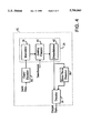
- FIG. 4 is a block diagram of an alternate configuration of a digital communications system having an encoder, error burst detector, and decoder capable of providing error correction on transmitted data;
- FIG. 5 is a block diagram of a possible implementation of an error burst detector suited for use in the digital communications system of FIG. 3;
- FIG. 6 is a block diagram of a possible implementation of an error burst detector suited for use in the digital communications system of FIG. 4.
- FIG. 3 represents a digital communications system 24 which employs a concatenated encoding and decoding scheme.
- Digital communications system 24 comprises an equivalent discrete transmission channel 26 interposed between an encoder 28 and a decoder 30.
- Error burst detector 50 is coupled to channel 26 and decoder 30.
- Digital communications system 24 in conjunction with encoder 28, decoder 30, and error burst detector 50 serves to error correct digital signals sent through channel 26. Error correction coding makes the digital signals less susceptible to noise and other forms of interference on the channel.
- Digital communications system 24 employs a more efficient decoder 30 which can correct a larger number of data symbol errors than conventional decoders at a comparable level of system complexity. More specifically, decoder 30 uses additional information provided by error burst detector 50 to determine the location of suspected code symbol errors and thereafter ignores code symbols in those locations upon decode. Decoder 30, in conjunction with error detector 50, is thereby capable of correcting a larger number of code symbol errors than conventional decoders. Decoder 30, in conjunction with error burst detector 50, is particularly well suited to decoding information transmitted across communications channels which are prone to random or burst errors.
- Encoder 28 shown in the embodiment of FIG. 3 is a concatenated encoder.
- a preferred concatenated encoder hereof employs an inner, convolutional encoder 32, an outer, Reed-Solomon block encoder 34 and an interleaver 36 placed between the encoders.
- the input data is error correction encoded and thereafter conveyed across discrete time channel 26.
- Discrete time channel 26 normally comprises a modulator 38 and a demodulator 42 operably connected by an analog channel 40.
- Modulator 38 can use any well known modulation technique, suitable modulation being amplitude modulation, frequency shift keying, phase shift keying, etc. Whatever modulation scheme is used, the desired modulation output is one that is less susceptible to interference on channel 40.
- Analog channel 40 is typically subject to interference which may corrupt signals forwarded therein.
- the interference may cause symbol errors at certain code word locations present at the output of demodulator 42.
- analog channel 40 may take the form of a transmitting antenna from which microwaves are emitted, atmosphere and empty space through which the microwaves travel, a satellite which reflects or receives and retransmits the microwaves, and a receiving antenna which converts the microwaves into an electrical signal.
- the channel interference may result from atmospheric noise, multi-path interference, and fading. Other forms of noise may arise from electronic circuitry within the modulator 38 and demodulator 42.
- Other channels which might be used in communications system 24 include cable transmission channels and magnetic recording channels.
- demodulator 42 which serves to reproduce the coded digital signal from the carrier waveform.
- demodulator 42 may employ an amplifier and various filters. Regardless of the form chosen, the desired output of demodulator 42 is a coded digital signal which is as free of interference as possible. However, interference cannot be entirely eliminated from the encoded signal, which consequently motivates the use of error correction coding.
- output from demodulator 42 is forwarded to decoder 30, but also to error burst detector 50.
- Decoder 30 decodes the coded digital signal preferably using an inner Viterbi decoder 44, a deinterleaver 48, and an outer Reed-Solomon decoder 46.
- decoder 30 accepts output from error burst detector 50 which flags locations of suspected symbol errors in the coded digital signal. With the additional information provided by the determination of the symbol errors, outer decoder 46 is able to correct a larger number of symbol errors than a conventional decoder of similar complexity.
- the outer decoder 46 In systems where the prevalent error type is burst errors, the main benefit of erasures is to be gained by the outer decoder 46.
- the inner decoder is normally designed to correct isolated random errors. However the burst errors may only be dealt with by codes with large Hamming distances. This motivates the presence of the outer decoder in a concatenated decoder design. Since the use of erasures permits the use of codes with reduced Hamming distances, implementation complexity of the outer decoder is significantly reduced.
- Error burst detector 58 functions to measure the noise level on discrete time channel 26 and thereafter set symbol error flags based on criteria related to the noise level. Such criteria may include the noise level or a time averaged measurement of the noise level exceeding a predetermined threshold value. Alternatively, the error burst criteria might include sudden changes in the noise level, or a combination of the value and derivative of the noise level. In any case, the symbol error locations are determined prior to decoding, and hence may be used to advantage by the entire decoder 56. Decoder 56 may be implemented in the form of a block decoder, a convolutional decoder, or a concatenated decoder.
- de-interleaver 48 reverses the interleave operation performed by interleaver 36.
- Flag information from error burst detector 50 is processed so that symbols flagged at the input to the de-interleaver 48 remain flagged at the output of the de-interleaver 48.
- One method for doing this is to simply add a flag bit to each symbol as it is written into a de-interleaving mechanism modified to handle the augmented symbols. Then as the augmented symbols exit the de-interleaver the flag status of a given symbol is easily determined.
- error burst detector 50 accepts output symbols from inner decoder 44 and re-encodes the output symbols using an inner encoder 60 which implements the same encoding function as inner encoder 32.
- the resulting code symbol sequence output from inner encoder 60 serves as an approximation of the input to discrete time channel 26. Location of symbol errors is easy to achieve by comparing the input to channel 26 and output from channel 26. Although the input to channel 26 is not readily available, the approximation provided by the output of encoder 60 will be faithful when isolated random symbol errors occur. This is true since isolated random symbol errors are within the error correction capability of the inner decoder.
- the decoding and re-encoding of the channel output effectively implements the error correction.
- the approximation of the input to discrete time channel 26 will be extremely poor when many symbol errors occur in a small amount of time (i.e. burst errors). Since the error correction capability of the inner decoder is overwhelmed by the number of errors present in a burst error, the decoding and re-encoding of the channel output effectively results in wild guesses as to the input of the channel. These guesses are wrong more often than right, but more importantly, the correspondence with actual channel output is low. This characteristic permits the identification of the portions of the channel output signal sequence in which burst errors occur. For reasons outlined later, this results in a reliable identification of symbol error locations.
- Data delay line 62 serves to store the output signal from channel 26 until the inner decoder 44 and inner encoder 60 have produced an approximation of the input signal to channel 26.
- Comparator 64 compares the approximation of the input signal to the output signal and determines the presence or absence of a symbol error. This determination is passed in the form of a signal to a windowing filter 66 that determines the number of symbol errors in an interval which includes a predetermined number of code symbols. A signal representing this number is sent to threshold detector 68 which functions to determine whether the number of symbol errors in the specified interval exceeds a predetermined threshold. Threshold detector 68 outputs an error flag signal representing the presence or absence of a burst error in the specified interval.
- De-interleaver 48 is coupled to receive the error flag signal, and will use it to attach a flag bit to a subset of the code symbols that reside in the specified interval.
- the windowing filter 66 serves to determine the number of symbol errors in a specified interval. This is done to identify burst errors which are characterized as many errors occurring in a localized interval. The number of errors and the size of the interval which are used to differentiate a burst error from a series of random errors are specified by the system designer based on measured channel characteristics.
- One implementation for filter 66 is a shift register of a specified length that stores the output of comparator 64, and a summer that sums the contents of the shift register.
- the intent of the error flags is to mark as errors all of the code symbols that occur during an error burst on the basis that the symbols represent guesses by the inner decoder 44 and are most likely wrong.
- the probability of a particular symbol not being in error during an error burst is dependent on the statistics of the channel 26 and the decoder 30, but in general the probability is inversely proportional to the cardinality of the symbol set. For the large symbol sets normally used in Reed-Solomon codes, the probability of symbol error approaches 100%. Consequently, the erasure of these symbols is advantageous and leads to significant improvement in decoding performance of outer decoder 46.
- FIG. 6 illustrates one possible configuration for an error burst detector 58.
- Error burst detector 58 comprises a decision element 72, and a comparator 74 with inputs coupled to the input and output signals of decision element 72.
- the output of the comparator may take the form of an absolute value of the difference between the input signals or perhaps the square of the difference between the input signals.
- Error detector 58 may further comprise a windowing filter 76 and a threshold detector 78.
- Windowing filter 76 forms a signal determined by a weighted moving average of the comparator output signal. Windowing filter 76 is designed such that the resulting signal has a significant correlation with the presence of errors in the demodulated signal stream.
- Threshold detector 78 asserts an error flag whenever the windowing filter output exceeds a configurable threshold.
- Error burst detector may additionally comprise an equalizer 70. Equalizer 70 would then serve to remove intersymbol interference from the demodulator output and/or improve the signal-to-noise ratio.
- Decision element 72 may take the form of one or more comparators, each of which simply determines whether the channel output signal is greater than or less than a given value.
- the given values are chosen to be the midpoints between modulation points in the signal constellation. In this manner, the decision element is able to find the modulation point closest to the channel signal, and arbitrarily "decides" that the closest modulation point is the correct one. This is often referred to as making a hard decision.
- the distance between the channel output signal and the correct modulation point is determined by the interference of the channel. If the channel were perfect, the channel output signal would be equal to the correct modulation point. By taking the absolute value or square of the distance, a signal representing the level of the noise on the channel is generated. This noise signal can then be processed in one of several manners. An estimated noise power can be generated by averaging a fixed number of past noise signals. It is expected that an error burst will be characterized by a sudden jump in the difference between the current and previously estimated noise power. When threshold detector 78 to detects this sudden jump, the corresponding symbol locations in the channel output have an error flag set.
- Equalizer 70 is typically used to combat sources of channel interference which are not random, such as intersymbol interference. This simplifies the implementation of the decision element for complex channels and permits a more accurate estimation of noise.
- the communications system configuration of FIG. 4 might generally be preferred for high-order constellations, i.e. when the signal can consist of many signal points. In this case a greater need exists for equalization to improve the receiver's ability to distinguish between signal points.
- the communications system configuration of FIG. 3 might generally be preferred for channels which necessitate a large coding gain. These include power limited channels such as satellite channels are prone to a higher probability of error, and consequently require a code with a higher error correction capability.
Landscapes
- Engineering & Computer Science (AREA)
- Computer Networks & Wireless Communication (AREA)
- Signal Processing (AREA)
- Quality & Reliability (AREA)
- Error Detection And Correction (AREA)
- Detection And Prevention Of Errors In Transmission (AREA)
Abstract
Description
n.sub.E +2n.sub.e ≦d.sub.min.sup.H -1
Claims (14)
Priority Applications (1)
| Application Number | Priority Date | Filing Date | Title |
|---|---|---|---|
| US08/701,710 US5708665A (en) | 1996-08-22 | 1996-08-22 | Digital receiver using equalization and block decoding with erasure and error correction |
Applications Claiming Priority (1)
| Application Number | Priority Date | Filing Date | Title |
|---|---|---|---|
| US08/701,710 US5708665A (en) | 1996-08-22 | 1996-08-22 | Digital receiver using equalization and block decoding with erasure and error correction |
Publications (1)
| Publication Number | Publication Date |
|---|---|
| US5708665A true US5708665A (en) | 1998-01-13 |
Family
ID=24818363
Family Applications (1)
| Application Number | Title | Priority Date | Filing Date |
|---|---|---|---|
| US08/701,710 Expired - Lifetime US5708665A (en) | 1996-08-22 | 1996-08-22 | Digital receiver using equalization and block decoding with erasure and error correction |
Country Status (1)
| Country | Link |
|---|---|
| US (1) | US5708665A (en) |
Cited By (25)
| Publication number | Priority date | Publication date | Assignee | Title |
|---|---|---|---|---|
| US5802107A (en) * | 1996-09-13 | 1998-09-01 | Zenith Electronics Corporation | Symbol rotator |
| US5926489A (en) * | 1996-11-22 | 1999-07-20 | Lsi Logic Corporation | Non-equalized digital receiver using block decoding with erasure and error correction |
| US5942003A (en) * | 1996-12-23 | 1999-08-24 | Lsi Logic Corporation | Error burst detector for lowering receiver bit error rate |
| US5949790A (en) * | 1995-04-11 | 1999-09-07 | Nokia Mobile Phones Limited | Data transmission method, and transmitter |
| US5953636A (en) * | 1996-10-30 | 1999-09-14 | Lsi Logic Corporation | Single-chip DBS receiver |
| US5955783A (en) * | 1997-06-18 | 1999-09-21 | Lsi Logic Corporation | High frequency signal processing chip having signal pins distributed to minimize signal interference |
| US5970075A (en) * | 1997-06-18 | 1999-10-19 | Uniden San Diego Research And Development Center Inc. | Method and apparatus for generating an error location polynomial table |
| US6357029B1 (en) * | 1999-01-27 | 2002-03-12 | Agere Systems Guardian Corp. | Joint multiple program error concealment for digital audio broadcasting and other applications |
| US20030099316A1 (en) * | 2000-05-17 | 2003-05-29 | Citta Richard W. | Code enhanced equalization based upon a reliability factor |
| GB2396083A (en) * | 2002-12-03 | 2004-06-09 | Matsushita Electric Ind Co Ltd | Frame error detection |
| US20040190662A1 (en) * | 1998-03-31 | 2004-09-30 | Zenith Electronics Corporation | Code enhanced equalization based upon a reliability factor |
| US20060044162A1 (en) * | 2002-12-27 | 2006-03-02 | Phyworks Limited | Fibre optic communications |
| US7061205B2 (en) * | 2002-04-23 | 2006-06-13 | Sumitomo Electric Industries, Ltd. | Method for operating redox flow battery system |
| US7089324B1 (en) | 2001-06-14 | 2006-08-08 | Gateway Inc. | Dynamic internet gateway service |
| US20060242546A1 (en) * | 2002-04-05 | 2006-10-26 | Alion Science And Technology Corp. | Decoding method and apparatus |
| US20070016839A1 (en) * | 2005-07-15 | 2007-01-18 | Rong-Liang Chiou | Error-correcting apparatus including multiple error-correcting modules functioning in parallel and related method |
| US20070022357A1 (en) * | 2005-07-19 | 2007-01-25 | Rong-Liang Chiou | Apparatus selectively adopting different determining criteria in erasure marking procedure when performing decoding process, and method thereof |
| US7289530B1 (en) * | 2003-04-14 | 2007-10-30 | Applied Micro Circuits Corporation | System and method for coding a digital wrapper frame |
| US20080201628A1 (en) * | 2007-02-16 | 2008-08-21 | Mediatek Inc. | Apparatus and method for determining a detected punctured position in punctured convolutional codes |
| US20080222461A1 (en) * | 2007-03-09 | 2008-09-11 | Mediatek Inc. | Apparatus and method for calculating error metrics in a digital communication system |
| US20100235711A1 (en) * | 2009-03-10 | 2010-09-16 | Jaehong Kim | Data Processing System with Concatenated Encoding and Decoding Structure |
| US8286051B2 (en) | 2005-07-15 | 2012-10-09 | Mediatek Inc. | Method and apparatus for burst error detection and digital communication device |
| US20140101522A1 (en) * | 2012-10-05 | 2014-04-10 | Renesas Mobile Corporation | Method and apparatus for signal detection and decoding |
| US20140105202A1 (en) * | 2004-02-13 | 2014-04-17 | Broadcom Corporation | Encoding system and method for a transmitter in wireless communications |
| US10700800B2 (en) | 2003-05-21 | 2020-06-30 | Regents Of The University Of Minnesota | Estimating frequency-offsets and multi-antenna channels in MIMO OFDM systems |
Citations (2)
| Publication number | Priority date | Publication date | Assignee | Title |
|---|---|---|---|---|
| US4829525A (en) * | 1986-10-24 | 1989-05-09 | Mitsubishi Denki Kabushiki Kaisha | PCM signal reproducing apparatus including error/erasure correction circuit |
| US5430743A (en) * | 1993-06-29 | 1995-07-04 | Motorola, Inc. | Method and apparatus for recovering data in a radio communication system |
-
1996
- 1996-08-22 US US08/701,710 patent/US5708665A/en not_active Expired - Lifetime
Patent Citations (2)
| Publication number | Priority date | Publication date | Assignee | Title |
|---|---|---|---|---|
| US4829525A (en) * | 1986-10-24 | 1989-05-09 | Mitsubishi Denki Kabushiki Kaisha | PCM signal reproducing apparatus including error/erasure correction circuit |
| US5430743A (en) * | 1993-06-29 | 1995-07-04 | Motorola, Inc. | Method and apparatus for recovering data in a radio communication system |
Cited By (39)
| Publication number | Priority date | Publication date | Assignee | Title |
|---|---|---|---|---|
| US5949790A (en) * | 1995-04-11 | 1999-09-07 | Nokia Mobile Phones Limited | Data transmission method, and transmitter |
| US5802107A (en) * | 1996-09-13 | 1998-09-01 | Zenith Electronics Corporation | Symbol rotator |
| US5953636A (en) * | 1996-10-30 | 1999-09-14 | Lsi Logic Corporation | Single-chip DBS receiver |
| US5926489A (en) * | 1996-11-22 | 1999-07-20 | Lsi Logic Corporation | Non-equalized digital receiver using block decoding with erasure and error correction |
| US5942003A (en) * | 1996-12-23 | 1999-08-24 | Lsi Logic Corporation | Error burst detector for lowering receiver bit error rate |
| US5955783A (en) * | 1997-06-18 | 1999-09-21 | Lsi Logic Corporation | High frequency signal processing chip having signal pins distributed to minimize signal interference |
| US5970075A (en) * | 1997-06-18 | 1999-10-19 | Uniden San Diego Research And Development Center Inc. | Method and apparatus for generating an error location polynomial table |
| US8144750B2 (en) | 1998-03-31 | 2012-03-27 | Zenith Electronics Llc | Code enhanced equalization based upon a reliability factor |
| US20040190662A1 (en) * | 1998-03-31 | 2004-09-30 | Zenith Electronics Corporation | Code enhanced equalization based upon a reliability factor |
| US6357029B1 (en) * | 1999-01-27 | 2002-03-12 | Agere Systems Guardian Corp. | Joint multiple program error concealment for digital audio broadcasting and other applications |
| KR100742102B1 (en) * | 1999-01-27 | 2007-07-25 | 루센트 테크놀러지스 인크 | Joint multiple program error concealment for digital audio broadcasting and other applications |
| US20030099316A1 (en) * | 2000-05-17 | 2003-05-29 | Citta Richard W. | Code enhanced equalization based upon a reliability factor |
| US8718197B2 (en) * | 2000-05-17 | 2014-05-06 | Zenith Electronics Llc | Code enhanced equalization based upon a reliability factor |
| US7089324B1 (en) | 2001-06-14 | 2006-08-08 | Gateway Inc. | Dynamic internet gateway service |
| US20060242546A1 (en) * | 2002-04-05 | 2006-10-26 | Alion Science And Technology Corp. | Decoding method and apparatus |
| US7061205B2 (en) * | 2002-04-23 | 2006-06-13 | Sumitomo Electric Industries, Ltd. | Method for operating redox flow battery system |
| AU2003227441B2 (en) * | 2002-04-23 | 2007-12-20 | Sumitomo Electric Industries, Ltd. | Method for operating redox flow battery system |
| GB2396083A (en) * | 2002-12-03 | 2004-06-09 | Matsushita Electric Ind Co Ltd | Frame error detection |
| US20060044162A1 (en) * | 2002-12-27 | 2006-03-02 | Phyworks Limited | Fibre optic communications |
| US7289530B1 (en) * | 2003-04-14 | 2007-10-30 | Applied Micro Circuits Corporation | System and method for coding a digital wrapper frame |
| US11303377B2 (en) | 2003-05-21 | 2022-04-12 | Regents Of The University Of Minnesota | Estimating frequency-offsets and multi-antenna channels in MIMO OFDM systems |
| US10700800B2 (en) | 2003-05-21 | 2020-06-30 | Regents Of The University Of Minnesota | Estimating frequency-offsets and multi-antenna channels in MIMO OFDM systems |
| US8996949B2 (en) * | 2004-02-13 | 2015-03-31 | Broadcom Corporation | Encoding system and method for a transmitter in wireless communications |
| US20140105202A1 (en) * | 2004-02-13 | 2014-04-17 | Broadcom Corporation | Encoding system and method for a transmitter in wireless communications |
| US8209583B2 (en) | 2005-07-15 | 2012-06-26 | Mediatek Inc. | Error-correcting apparatus including multiple error-correcting modules functioning in parallel and related method |
| US7673222B2 (en) | 2005-07-15 | 2010-03-02 | Mediatek Incorporation | Error-correcting apparatus including multiple error-correcting modules functioning in parallel and related method |
| US20100115382A1 (en) * | 2005-07-15 | 2010-05-06 | Rong-Liang Chiou | Error-correcting apparatus including multiple error-correcting modules functioning in parallel and related method |
| US20070016839A1 (en) * | 2005-07-15 | 2007-01-18 | Rong-Liang Chiou | Error-correcting apparatus including multiple error-correcting modules functioning in parallel and related method |
| US8286051B2 (en) | 2005-07-15 | 2012-10-09 | Mediatek Inc. | Method and apparatus for burst error detection and digital communication device |
| US20070022357A1 (en) * | 2005-07-19 | 2007-01-25 | Rong-Liang Chiou | Apparatus selectively adopting different determining criteria in erasure marking procedure when performing decoding process, and method thereof |
| US7603591B2 (en) | 2005-07-19 | 2009-10-13 | Mediatek Incorporation | Apparatus selectively adopting different determining criteria in erasure marking procedure when performing decoding process, and method thereof |
| US20080201628A1 (en) * | 2007-02-16 | 2008-08-21 | Mediatek Inc. | Apparatus and method for determining a detected punctured position in punctured convolutional codes |
| US7865812B2 (en) | 2007-02-16 | 2011-01-04 | Mediatek Inc. | Apparatus and method for determining a detected punctured position in punctured convolutional codes |
| US7890847B2 (en) | 2007-03-09 | 2011-02-15 | Mediatek Inc. | Apparatus and method for calculating error metrics in a digital communication system |
| US20080222461A1 (en) * | 2007-03-09 | 2008-09-11 | Mediatek Inc. | Apparatus and method for calculating error metrics in a digital communication system |
| US8510624B2 (en) * | 2009-03-10 | 2013-08-13 | Samsung Electronics Co., Ltd. | Data processing system with concatenated encoding and decoding structure |
| US20100235711A1 (en) * | 2009-03-10 | 2010-09-16 | Jaehong Kim | Data Processing System with Concatenated Encoding and Decoding Structure |
| US20140101522A1 (en) * | 2012-10-05 | 2014-04-10 | Renesas Mobile Corporation | Method and apparatus for signal detection and decoding |
| US9104569B2 (en) * | 2012-10-05 | 2015-08-11 | Broadcom Corporation | Method and apparatus for signal detection and decoding |
Similar Documents
| Publication | Publication Date | Title |
|---|---|---|
| US5812603A (en) | Digital receiver using a concatenated decoder with error and erasure correction | |
| US5708665A (en) | Digital receiver using equalization and block decoding with erasure and error correction | |
| US5926489A (en) | Non-equalized digital receiver using block decoding with erasure and error correction | |
| US5757821A (en) | Method and apparatus for detecting communication signals having unequal error protection | |
| US7609787B2 (en) | Reception of a signal modulated according to a multilevel coding technique | |
| US7502982B2 (en) | Iterative detector with ECC in channel domain | |
| JP3230766B2 (en) | Digital data communication method and apparatus using trellis coded QAM | |
| EP1350310B1 (en) | Reduced soft output information packet selection | |
| US8127216B2 (en) | Reduced state soft output processing | |
| US6543023B2 (en) | Parity-check coding for efficient processing of decoder error events in data storage, communication and other systems | |
| EP0854581A2 (en) | Coding and decoding system using crc check bit | |
| US6606724B1 (en) | Method and apparatus for decoding of a serially concatenated block and convolutional code | |
| US6269124B1 (en) | Data transmission system, receiver, and recording medium | |
| US5942003A (en) | Error burst detector for lowering receiver bit error rate | |
| US5742619A (en) | Method and apparatus for concatenated coding of mobile radio signals | |
| EP0897620B1 (en) | VERFAHREN ZUR DEKODIERUNG VON DATENSIGNALEN MITTELS EINES ENTSCHEIDUNGSFENSTERS fester Länge | |
| US8286051B2 (en) | Method and apparatus for burst error detection and digital communication device | |
| KR100666399B1 (en) | Receiver and signal processing method thereof | |
| EP1432128A2 (en) | Method and device for soft demodulation using a code table | |
| US5757863A (en) | Apparatus for decoding a signal encoded by using trellis coded modulation | |
| US7287209B2 (en) | System and method for detecting codeword errors in error correction code or cyclic redundancy check code | |
| US7254771B1 (en) | Error-erasure decoding of interleaved reed-solomon code | |
| US6947503B2 (en) | Method and circuit for synchronizing a receiver for a convolutionally coded reception signal | |
| Petrovic et al. | List Viterbi decoding with continuous error detection for magnetic recording | |
| US20040059991A1 (en) | Simple detector and method for QPSK symbols |
Legal Events
| Date | Code | Title | Description |
|---|---|---|---|
| AS | Assignment |
Owner name: LSI LOGIC CORPORATION, CALIFORNIA Free format text: ASSIGNMENT OF ASSIGNORS INTEREST;ASSIGNORS:LUTHI, DANIEL A.;BHASKARAN, RAVI;RHEE, DOJUN;AND OTHERS;REEL/FRAME:008165/0298 Effective date: 19960820 |
|
| STCF | Information on status: patent grant |
Free format text: PATENTED CASE |
|
| FPAY | Fee payment |
Year of fee payment: 4 |
|
| FPAY | Fee payment |
Year of fee payment: 8 |
|
| FEPP | Fee payment procedure |
Free format text: PAYOR NUMBER ASSIGNED (ORIGINAL EVENT CODE: ASPN); ENTITY STATUS OF PATENT OWNER: LARGE ENTITY Free format text: PAYER NUMBER DE-ASSIGNED (ORIGINAL EVENT CODE: RMPN); ENTITY STATUS OF PATENT OWNER: LARGE ENTITY |
|
| FPAY | Fee payment |
Year of fee payment: 12 |
|
| AS | Assignment |
Owner name: DEUTSCHE BANK AG NEW YORK BRANCH, AS COLLATERAL AG Free format text: PATENT SECURITY AGREEMENT;ASSIGNORS:LSI CORPORATION;AGERE SYSTEMS LLC;REEL/FRAME:032856/0031 Effective date: 20140506 |
|
| AS | Assignment |
Owner name: LSI CORPORATION, CALIFORNIA Free format text: CHANGE OF NAME;ASSIGNOR:LSI LOGIC CORPORATION;REEL/FRAME:033102/0270 Effective date: 20070406 |
|
| AS | Assignment |
Owner name: AVAGO TECHNOLOGIES GENERAL IP (SINGAPORE) PTE. LTD Free format text: ASSIGNMENT OF ASSIGNORS INTEREST;ASSIGNOR:LSI CORPORATION;REEL/FRAME:035390/0388 Effective date: 20140814 |
|
| AS | Assignment |
Owner name: LSI CORPORATION, CALIFORNIA Free format text: TERMINATION AND RELEASE OF SECURITY INTEREST IN PATENT RIGHTS (RELEASES RF 032856-0031);ASSIGNOR:DEUTSCHE BANK AG NEW YORK BRANCH, AS COLLATERAL AGENT;REEL/FRAME:037684/0039 Effective date: 20160201 Owner name: AGERE SYSTEMS LLC, PENNSYLVANIA Free format text: TERMINATION AND RELEASE OF SECURITY INTEREST IN PATENT RIGHTS (RELEASES RF 032856-0031);ASSIGNOR:DEUTSCHE BANK AG NEW YORK BRANCH, AS COLLATERAL AGENT;REEL/FRAME:037684/0039 Effective date: 20160201 |
|
| AS | Assignment |
Owner name: BANK OF AMERICA, N.A., AS COLLATERAL AGENT, NORTH CAROLINA Free format text: PATENT SECURITY AGREEMENT;ASSIGNOR:AVAGO TECHNOLOGIES GENERAL IP (SINGAPORE) PTE. LTD.;REEL/FRAME:037808/0001 Effective date: 20160201 Owner name: BANK OF AMERICA, N.A., AS COLLATERAL AGENT, NORTH Free format text: PATENT SECURITY AGREEMENT;ASSIGNOR:AVAGO TECHNOLOGIES GENERAL IP (SINGAPORE) PTE. LTD.;REEL/FRAME:037808/0001 Effective date: 20160201 |
|
| AS | Assignment |
Owner name: AVAGO TECHNOLOGIES GENERAL IP (SINGAPORE) PTE. LTD., SINGAPORE Free format text: TERMINATION AND RELEASE OF SECURITY INTEREST IN PATENTS;ASSIGNOR:BANK OF AMERICA, N.A., AS COLLATERAL AGENT;REEL/FRAME:041710/0001 Effective date: 20170119 Owner name: AVAGO TECHNOLOGIES GENERAL IP (SINGAPORE) PTE. LTD Free format text: TERMINATION AND RELEASE OF SECURITY INTEREST IN PATENTS;ASSIGNOR:BANK OF AMERICA, N.A., AS COLLATERAL AGENT;REEL/FRAME:041710/0001 Effective date: 20170119 |