US5706559A - Leaf spring tip insert - Google Patents
Leaf spring tip insert Download PDFInfo
- Publication number
- US5706559A US5706559A US08/732,733 US73273396A US5706559A US 5706559 A US5706559 A US 5706559A US 73273396 A US73273396 A US 73273396A US 5706559 A US5706559 A US 5706559A
- Authority
- US
- United States
- Prior art keywords
- insert
- leaf spring
- pad portion
- protuberances
- shank portion
- Prior art date
- Legal status (The legal status is an assumption and is not a legal conclusion. Google has not performed a legal analysis and makes no representation as to the accuracy of the status listed.)
- Expired - Fee Related
Links
- 230000037431 insertion Effects 0.000 claims 2
- 238000003780 insertion Methods 0.000 claims 2
- 230000004323 axial length Effects 0.000 description 2
- 230000014759 maintenance of location Effects 0.000 description 2
- 239000004809 Teflon Substances 0.000 description 1
- 229920006362 Teflon® Polymers 0.000 description 1
- 150000001875 compounds Chemical class 0.000 description 1
- 238000001125 extrusion Methods 0.000 description 1
- 229920001903 high density polyethylene Polymers 0.000 description 1
- 239000004700 high-density polyethylene Substances 0.000 description 1
- 238000009434 installation Methods 0.000 description 1
- 239000000463 material Substances 0.000 description 1
- 239000002184 metal Substances 0.000 description 1
- 239000008188 pellet Substances 0.000 description 1
- 238000000926 separation method Methods 0.000 description 1
Images


Classifications
-
- F—MECHANICAL ENGINEERING; LIGHTING; HEATING; WEAPONS; BLASTING
- F16—ENGINEERING ELEMENTS AND UNITS; GENERAL MEASURES FOR PRODUCING AND MAINTAINING EFFECTIVE FUNCTIONING OF MACHINES OR INSTALLATIONS; THERMAL INSULATION IN GENERAL
- F16B—DEVICES FOR FASTENING OR SECURING CONSTRUCTIONAL ELEMENTS OR MACHINE PARTS TOGETHER, e.g. NAILS, BOLTS, CIRCLIPS, CLAMPS, CLIPS OR WEDGES; JOINTS OR JOINTING
- F16B21/00—Means for preventing relative axial movement of a pin, spigot, shaft or the like and a member surrounding it; Stud-and-socket releasable fastenings
- F16B21/06—Releasable fastening devices with snap-action
- F16B21/08—Releasable fastening devices with snap-action in which the stud, pin, or spigot has a resilient part
- F16B21/088—Releasable fastening devices with snap-action in which the stud, pin, or spigot has a resilient part the stud, pin or spigot being integrally formed with the component to be fastened, e.g. forming part of the sheet, plate or strip
-
- F—MECHANICAL ENGINEERING; LIGHTING; HEATING; WEAPONS; BLASTING
- F16—ENGINEERING ELEMENTS AND UNITS; GENERAL MEASURES FOR PRODUCING AND MAINTAINING EFFECTIVE FUNCTIONING OF MACHINES OR INSTALLATIONS; THERMAL INSULATION IN GENERAL
- F16B—DEVICES FOR FASTENING OR SECURING CONSTRUCTIONAL ELEMENTS OR MACHINE PARTS TOGETHER, e.g. NAILS, BOLTS, CIRCLIPS, CLAMPS, CLIPS OR WEDGES; JOINTS OR JOINTING
- F16B5/00—Joining sheets or plates, e.g. panels, to one another or to strips or bars parallel to them
- F16B5/06—Joining sheets or plates, e.g. panels, to one another or to strips or bars parallel to them by means of clamps or clips
- F16B5/0607—Joining sheets or plates, e.g. panels, to one another or to strips or bars parallel to them by means of clamps or clips joining sheets or plates to each other
- F16B5/0621—Joining sheets or plates, e.g. panels, to one another or to strips or bars parallel to them by means of clamps or clips joining sheets or plates to each other in parallel relationship
- F16B5/065—Joining sheets or plates, e.g. panels, to one another or to strips or bars parallel to them by means of clamps or clips joining sheets or plates to each other in parallel relationship the plates being one on top of the other and distanced from each other, e.g. by using protrusions to keep contact and distance
-
- Y—GENERAL TAGGING OF NEW TECHNOLOGICAL DEVELOPMENTS; GENERAL TAGGING OF CROSS-SECTIONAL TECHNOLOGIES SPANNING OVER SEVERAL SECTIONS OF THE IPC; TECHNICAL SUBJECTS COVERED BY FORMER USPC CROSS-REFERENCE ART COLLECTIONS [XRACs] AND DIGESTS
- Y10—TECHNICAL SUBJECTS COVERED BY FORMER USPC
- Y10T—TECHNICAL SUBJECTS COVERED BY FORMER US CLASSIFICATION
- Y10T24/00—Buckles, buttons, clasps, etc.
- Y10T24/39—Cord and rope holders
- Y10T24/3996—Sliding wedge
-
- Y—GENERAL TAGGING OF NEW TECHNOLOGICAL DEVELOPMENTS; GENERAL TAGGING OF CROSS-SECTIONAL TECHNOLOGIES SPANNING OVER SEVERAL SECTIONS OF THE IPC; TECHNICAL SUBJECTS COVERED BY FORMER USPC CROSS-REFERENCE ART COLLECTIONS [XRACs] AND DIGESTS
- Y10—TECHNICAL SUBJECTS COVERED BY FORMER USPC
- Y10T—TECHNICAL SUBJECTS COVERED BY FORMER US CLASSIFICATION
- Y10T24/00—Buckles, buttons, clasps, etc.
- Y10T24/42—Independent, headed, aperture pass-through fastener
Definitions
- This invention relates generally to the securing of a low friction pad for improving ride characteristics and reducing noise and wear between adjacent leaves of a vehicular leaf spring during operation of a vehicle.
- Nonmetallic, generally polymeric, tip inserts or separator pads have been used between adjacent vehicular leaf spring plates for many years as a means of reducing friction, noise and wear and improving ride as the plates slide relative to each other when the spring flexes during operation of the vehicle.
- An example involving the use of round metal pellets may be found in U.S. Pat. No. 2,621,921, the disclosure of which is incorporated herein by reference.
- the present invention provides an insert having a shank portion adapted to secure the insert to the tips of leaf spring plates having a range of thicknesses and a pad portion adapted to provide separation between adjacent leaf spring plates.
- the insert of the present invention has the advantage of being securable to spring leaves having a range of thicknesses, as well as the particular advantage of requiring substantially less force to press through the leaf spring plate opening and requiring a greater force to remove the insert from the leaf spring plate to which it is releasably secured when compared to a prior art type insert having a shank portion divided into only two parts as shown in FIGS. 12 and 13.
- FIG. 1 is a side elevation view of an embodiment of the insert of the invention reference by numeral 50;
- FIG. 2 is a view of insert 50 taken along view line 2--2 in FIG. 1;
- FIG. 3 is a partial cross-section view of insert 50 of FIGS. 1 and 2 providing a pad between leaf spring plates 22 and 24;
- FIG. 4 is a partial cross-section view of insert 50 of FIGS. 1 and 2 providing a pad 3 between leaf spring plates 32 and 34;
- FIG. 5 is a side elevation view of another embodiment of the insert of the invention referenced by numeral 100;
- FIG. 6 is a view of insert 100 taken along view line 6--6 in FIG. 5.
- FIG. 7 is a side elevation view of another embodiment of the insert of the invention referenced by numeral 150;
- FIG. 8 is a view of insert 150 taken along view line 8--8 in FIG. 7.
- FIG. 9 is a side elevation view of another embodiment of the insert of the invention referenced by numeral 200;
- FIG. 10 is a view of insert 200 taken along view line 10--10 in FIG. 9;
- FIG. 11 is a side elevation view of an embodiment of the invention referenced by numeral 250 having a pair of spaced apart shank portions 48 and 50;
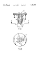
- FIG. 12 is a side elevation view of a prior art type tip liner insert.
- FIG. 13 is a view of the prior art type tip liner insert taken along view line 13--13 in FIG. 12.
- insert 50 has a pad portion 3 that is adapted to provide a liner between leaf spring plate tip ends, as shown in FIGS. 3 and 4.
- a shank portion 4 preferably extends substantially perpendicularly from pad portion 3 to a free end 7.
- Orthogonal slots 12 and 12' extend from free end 7 for a prescribed axial distance toward pad portion 3 and divide shaft 4 into four resilient elongated segments having respective corresponding diametrically opposed protuberances 14, 14' and 16, 16' that respectively extend radially outwardly to provide a diametrical width "Z" that, along with the width of slots 12 and 12', is predetermined to enable the segments to compress radially inwardly sufficiently to enable them to be received through the leaf spring tip opening into which shaft 4 is inserted.
- Diametrically opposed protuberances 14 and 14' have corresponding leaf spring engagement surfaces 18 and 18' that face toward liner portion 3 and are in substantial registration with each other at a prescribed axial distance "X" therefrom.
- diametrically opposed protuberances 16 and 16' have corresponding arcuate leaf spring engagement surfaces 20 and 20' that face toward pad portion 3 and are in substantial registration with each other at an axial distance "Y" from pad portion 3 that is greater than distance "X.”
- insert 50 to be securely attached to leaf spring plates having a range of thicknesses, as shown in FIGS. 3 and 4.
- Protuberances 14, 14' and 16, 16' are configured to cause them to compress radially inwardly as shaft portion 4 is inserted into the leaf spring tip opening such as by having their respective outer surfaces tapered angularly inwardly in a direction toward free end 7 at an angle "A,” of which 20° has been found to be particularly effective in reducing force of inserting/installation.
- slots 12 and 12' may be flared outwardly at angle "B" for a prescribed length from free end 7, of which 5°-6° from the center line to provide a preferred included angle of about 10°-12° has been found to be particularly effective.
- insert 50 is being utilized to provide a space (pad portion 3) between leaf spring plates 22 and 24.
- the thickness of plate 24 (not referenced) is the same or less than length "X" in FIG. 1 such that when shaft portion 4 is inserted through opening 26 of leaf spring plate 24 until the underside of liner portion 3 abuts against plate 24, protuberances 14, 14' and 16, 16' spring or expand outwardly to enable surfaces 18 and 18' to be engageable with the underside of spring plate 24 to lockingly secure insert 50 to spring plate 24, while plate engagement surfaces 20 and 20' of protuberances 16 and 16' respectively remain at a prescribed distance "T" away from the underside of spring plate 24.
- leaf spring plate 34 has a thickness (not referenced) that is greater than length "X" and the same or less than length "Y” in FIG. 1 such that arcuate surfaces 20 and 20' of protuberances 16 and 16' respectively are engageable with the underside of leaf spring plate 34, while protuberances 14 and 14' remain compressed within opening 29, as referenced by numeral 28.
- FIGS. 5-10 illustrate that the pad portion and shank portion of the insert of the invention are not limited to any particular configuration.
- pad portion 36 of insert 100 is in the form of a flat plate, while shank portion 38 has a substantially circular cross-sectional configuration to eliminate orientation requirements, while the axial distance between the shank portion free end and the pad portion of one pair of diametrically opposed protuberances is less by the axial length "U" than the other.
- pad portion 40 of insert 150 has a domed configuration to reduce contact area to prevent retention of road debris and shank portion 42 has a generally oval cross-section to improve shank shear strength and prevent rotation with the free-end of one segment referenced by numeral 41 and another by numeral 43.
- the dome-shape may have a asymmetrical configuration with its thickest section off-set from center if such is desired.
- pad portion 44 of insert 200 has a generally wedge-shaped cross-section to assure adjacent leaf contact at the furthest portion of the plate tip, whereas shank portion 46 has a generally trapezoidal cross-sectional configuration to assure orientation of the high point wedge of the pad to the furthest point on the tip with one segment free-end referenced by numeral 48 and another by numeral 50.
- Insert 250 of FIG. 11 illustrates that the insert of the invention may have more than one shank portion such as spaced-apart shank portions 52 and 54 that respectively extend preferably substantially perpendicularly from one side of the pad portion 250.
- the use of such spaced-apart shank portions is effective in preventing twisting of the pad portion 250 during operation of the vehicle.
- Inserts 150, 200 and 250 also illustrate that, unlike inserts 50 and 100 of FIGS. 1 and 5, the two slots dividing the shank portion into four segments need not be orthogonal to each other and may be at any angular orientation to each other including parallel as shown in FIGS. 8 and 10.
- the pad portion of the tip liner insert has heretofore been limited to a plate-like configuration having a substantially uniform thickness throughout such as shown in FIGS. 1, 5, and 11. It is believed therefor that the dome-shaped pad portion 40 shown in FIG. 7 and the wedge-shaped pad portion 44 shown in FIG. 9 are in themselves novel configurations having utility and thus patentable in combination with any type of shank portion including those covered by the present invention.
- the insert of the invention may be made from any material suitable to perform satisfactorily as a spaced pad between vehicular leaf spring plate tips, high-density polyethylene and nylon-teflon compounds have been found to be of particular advantage to reduce friction, avoid noise and yet have high wear resistance at relatively low cost.
Abstract
Description
Claims (11)
Priority Applications (2)
| Application Number | Priority Date | Filing Date | Title |
|---|---|---|---|
| US08/732,733 US5706559A (en) | 1996-10-18 | 1996-10-18 | Leaf spring tip insert |
| MXPA/A/1997/007986A MXPA97007986A (en) | 1996-10-18 | 1997-10-17 | Point insert for ho spring |
Applications Claiming Priority (1)
| Application Number | Priority Date | Filing Date | Title |
|---|---|---|---|
| US08/732,733 US5706559A (en) | 1996-10-18 | 1996-10-18 | Leaf spring tip insert |
Publications (1)
| Publication Number | Publication Date |
|---|---|
| US5706559A true US5706559A (en) | 1998-01-13 |
Family
ID=24944742
Family Applications (1)
| Application Number | Title | Priority Date | Filing Date |
|---|---|---|---|
| US08/732,733 Expired - Fee Related US5706559A (en) | 1996-10-18 | 1996-10-18 | Leaf spring tip insert |
Country Status (1)
| Country | Link |
|---|---|
| US (1) | US5706559A (en) |
Cited By (59)
| Publication number | Priority date | Publication date | Assignee | Title |
|---|---|---|---|---|
| US5881989A (en) * | 1997-03-04 | 1999-03-16 | Apple Computer, Inc. | Audio enclosure assembly mounting system and method |
| US5896357A (en) * | 1996-07-31 | 1999-04-20 | Asahi Kogaku Kogyo Kabushiki Kaisha | Shutter opening mechanism of data recording/reproducing device |
| US6044528A (en) * | 1999-03-08 | 2000-04-04 | Schottin; Thomas M. | Strap retainer |
| US6048127A (en) * | 1998-10-15 | 2000-04-11 | Ditto Sales, Inc. | Furniture ganging device |
| US6082842A (en) * | 1998-02-19 | 2000-07-04 | Ho; Hsin Chien | Separate type computer housing support frame structure |
| US6116435A (en) * | 1998-07-27 | 2000-09-12 | Young; Richard E. | Mounting channel member and mounting channel member assembly and anchor fastener therefor |
| US6311960B1 (en) * | 2000-07-12 | 2001-11-06 | Oxford Suspension, Inc. | Leaf spring tip insert with semi-liquid or thermally deformable retention pin |
| US6354574B1 (en) * | 2000-07-12 | 2002-03-12 | Oxford Suspension, Inc. | Leaf spring tip insert |
| US6517059B1 (en) * | 2000-07-17 | 2003-02-11 | Transnav, Inc. | Leaf spring insert and method for assembling a leaf spring |
| US20050016085A1 (en) * | 2003-07-25 | 2005-01-27 | Saldarelli Thomas A. | Arcuate taper lock anchor base plate and anchor assembly with the base plate |
| US20060079125A1 (en) * | 2001-03-06 | 2006-04-13 | Kidman Brent L | Connection box assembly method |
| US20070022588A1 (en) * | 2005-07-15 | 2007-02-01 | Fabworx Solutions, Inc. | O-ring locking mount |
| US20080038049A1 (en) * | 2005-02-25 | 2008-02-14 | Elringklinger Ag | Sleeve for pre-assembly of a flat gasket on a machine component |
| US20080134472A1 (en) * | 2006-12-08 | 2008-06-12 | Kosidlo John M | Retention clip |
| US20080250609A1 (en) * | 2004-04-09 | 2008-10-16 | Avery Dennison Corporation | Cable Tie With Insert Fastener |
| US20080276516A1 (en) * | 2007-03-12 | 2008-11-13 | Hannspree, Inc. | Frame structure adapted to different display panel thicknesses and corresponding engaging device |
| US7455192B2 (en) | 2004-11-03 | 2008-11-25 | Illinois Tool Works Inc. | Overmolded adhesive hole plug |
| US20090152905A1 (en) * | 2007-12-14 | 2009-06-18 | Toyota Motor Engineering & Manufacturing North America, Inc. | Molded Headliner Reinforcement |
| US20090293667A1 (en) * | 2008-05-30 | 2009-12-03 | Ogburn Sean T | Grab bar end cap |
| US20100025547A1 (en) * | 2008-07-31 | 2010-02-04 | Smutny Dale J | Clip for fastening an article to a panel having a self-expanding clip head |
| US20100163267A1 (en) * | 2005-01-11 | 2010-07-01 | Kidman Brent L | Wide safety strap for electrical fixtures |
| US20110203828A1 (en) * | 2006-07-18 | 2011-08-25 | Leviton Manufacturing Co., Inc. | Wiring device and cover plate snap-on assembly |
| US20110305500A1 (en) * | 2010-06-09 | 2011-12-15 | World Wide Stationery Manufacturing Co., Ltd. | Ring binder mechanism having unitary structure |
| WO2012001035A1 (en) * | 2010-07-01 | 2012-01-05 | Continental Teves Ag & Co. Ohg | Fastening device |
| CN102729691A (en) * | 2011-04-08 | 2012-10-17 | 国际文具制造厂有限公司 | Hinge clamp mechanism with rings in integral structure |
| US8905858B2 (en) * | 2012-08-06 | 2014-12-09 | Dunlop Sports Co., Ltd. | Club head with insert including securing member on outer surface |
| US20150093177A1 (en) * | 2013-09-27 | 2015-04-02 | GM Global Technology Operations LLC | Elastically averaged alignment systems and methods |
| US20160058213A1 (en) * | 2014-09-02 | 2016-03-03 | IXXI Concepts Group B.V. | Wall decoration assembly, kit for making a wall decoration assembly and method for hanging such assembly |
| CN105673752A (en) * | 2014-12-05 | 2016-06-15 | 通用汽车环球科技运作有限责任公司 | Noise reduction for rear suspension leaf spring with tip insert - round head |
| US9428123B2 (en) | 2013-12-12 | 2016-08-30 | GM Global Technology Operations LLC | Alignment and retention system for a flexible assembly |
| US9428046B2 (en) | 2014-04-02 | 2016-08-30 | GM Global Technology Operations LLC | Alignment and retention system for laterally slideably engageable mating components |
| US9429176B2 (en) | 2014-06-30 | 2016-08-30 | GM Global Technology Operations LLC | Elastically averaged alignment systems and methods |
| US9447806B2 (en) | 2013-12-12 | 2016-09-20 | GM Global Technology Operations LLC | Self-retaining alignment system for providing precise alignment and retention of components |
| US9457845B2 (en) | 2013-10-02 | 2016-10-04 | GM Global Technology Operations LLC | Lobular elastic tube alignment and retention system for providing precise alignment of components |
| US9458876B2 (en) | 2013-08-28 | 2016-10-04 | GM Global Technology Operations LLC | Elastically deformable alignment fastener and system |
| US9463831B2 (en) | 2013-09-09 | 2016-10-11 | GM Global Technology Operations LLC | Elastic tube alignment and fastening system for providing precise alignment and fastening of components |
| US9481317B2 (en) | 2013-11-15 | 2016-11-01 | GM Global Technology Operations LLC | Elastically deformable clip and method |
| US9511802B2 (en) | 2013-10-03 | 2016-12-06 | GM Global Technology Operations LLC | Elastically averaged alignment systems and methods |
| US9541113B2 (en) | 2014-01-09 | 2017-01-10 | GM Global Technology Operations LLC | Elastically averaged alignment systems and methods |
| US9573432B2 (en) | 2013-10-01 | 2017-02-21 | Hendrickson Usa, L.L.C. | Leaf spring and method of manufacture thereof having sections with different levels of through hardness |
| US9599279B2 (en) | 2013-12-19 | 2017-03-21 | GM Global Technology Operations LLC | Elastically deformable module installation assembly |
| US9618026B2 (en) | 2012-08-06 | 2017-04-11 | GM Global Technology Operations LLC | Semi-circular alignment features of an elastic averaging alignment system |
| US9657807B2 (en) | 2014-04-23 | 2017-05-23 | GM Global Technology Operations LLC | System for elastically averaging assembly of components |
| US9669774B2 (en) | 2013-10-11 | 2017-06-06 | GM Global Technology Operations LLC | Reconfigurable vehicle interior assembly |
| US20170234349A1 (en) * | 2014-10-20 | 2017-08-17 | Rs Sourcing Limited | Fastener arrangements and articles comprising same |
| US9758110B2 (en) | 2015-01-12 | 2017-09-12 | GM Global Technology Operations LLC | Coupling system |
| US9812684B2 (en) | 2010-11-09 | 2017-11-07 | GM Global Technology Operations LLC | Using elastic averaging for alignment of battery stack, fuel cell stack, or other vehicle assembly |
| US9863454B2 (en) | 2013-08-07 | 2018-01-09 | GM Global Technology Operations LLC | Alignment system for providing precise alignment and retention of components of a sealable compartment |
| USD839197S1 (en) * | 2017-06-13 | 2019-01-29 | Dai-Ichi Seiko Co., Ltd. | Electrical connector housing |
| US10273995B2 (en) | 2015-12-28 | 2019-04-30 | David L. Pulsipher | Tarp connector |
| EP2600025B1 (en) * | 2010-07-26 | 2019-08-07 | NHK Spring Co., Ltd. | Silencer for a multi-leaf spring |
| US10410681B1 (en) * | 2018-07-23 | 2019-09-10 | Seagate Technology Llc | Printed circuit board snap-in mounting |
| USD859972S1 (en) | 2016-07-29 | 2019-09-17 | David L. Pulsipher | Connector |
| WO2019209399A1 (en) * | 2018-04-27 | 2019-10-31 | Illinois Tool Works Inc. | Snap fit fasteners |
| US20220136550A1 (en) * | 2020-10-30 | 2022-05-05 | Illinois Tool Works Inc. | Fastening device |
| US11731937B2 (en) | 2020-01-29 | 2023-08-22 | Advansix Resins & Chemicals Llc. | Amino acid surfactants |
| US11795143B2 (en) | 2020-01-29 | 2023-10-24 | Advansix Resins & Chemicals Llc | Amino acid surfactants |
| US11912930B2 (en) | 2020-03-11 | 2024-02-27 | Advansix Resins & Chemicals Llc | Formulation for the recovery of hydrocarbons including a surfactant system |
| TWI833734B (en) | 2018-04-27 | 2024-03-01 | 美商伊利諾工具工程公司 | Snap fit fasteners |
Citations (15)
| Publication number | Priority date | Publication date | Assignee | Title |
|---|---|---|---|---|
| US829837A (en) * | 1905-09-06 | 1906-08-28 | Martin William F | Garment-fastener. |
| US1365411A (en) * | 1920-06-30 | 1921-01-11 | Samuel G Kearney | Guy-clamp |
| US2133871A (en) * | 1937-02-27 | 1938-10-18 | Yankee Metal Products Corp | Fender guide |
| US2621921A (en) * | 1948-08-03 | 1952-12-16 | Studebaker Corp | Leaf spring |
| US2961723A (en) * | 1957-12-06 | 1960-11-29 | Illinois Tool Works | Molding clip |
| US3119299A (en) * | 1960-05-31 | 1964-01-28 | United Carr Fastener Corp | Fastening device |
| US3126185A (en) * | 1961-10-16 | 1964-03-24 | Cable clip means | |
| US3213500A (en) * | 1963-11-12 | 1965-10-26 | Master Mold & Die Company | Fastener |
| US3220078A (en) * | 1963-08-08 | 1965-11-30 | Elastic Stop Nut Corp | Rotary fastener |
| US3233502A (en) * | 1962-04-24 | 1966-02-08 | United Carr Inc | Resilient fastener with hollow shank |
| US3335471A (en) * | 1963-09-20 | 1967-08-15 | United Carr Inc | Fastener for metal plates |
| US3893208A (en) * | 1973-03-09 | 1975-07-08 | Nifco Inc | Plastic device for spacing and holding two or more plates |
| US3982844A (en) * | 1976-02-03 | 1976-09-28 | Mattel, Inc. | Tape fastening system |
| US4059938A (en) * | 1975-09-11 | 1977-11-29 | Itw Fastex Italia, S.P.A. | Adjustable molding end cap |
| US5219151A (en) * | 1990-03-22 | 1993-06-15 | Power Shield Corporation | Floating leaf spring separator pad and method for installing same |
-
1996
- 1996-10-18 US US08/732,733 patent/US5706559A/en not_active Expired - Fee Related
Patent Citations (15)
| Publication number | Priority date | Publication date | Assignee | Title |
|---|---|---|---|---|
| US829837A (en) * | 1905-09-06 | 1906-08-28 | Martin William F | Garment-fastener. |
| US1365411A (en) * | 1920-06-30 | 1921-01-11 | Samuel G Kearney | Guy-clamp |
| US2133871A (en) * | 1937-02-27 | 1938-10-18 | Yankee Metal Products Corp | Fender guide |
| US2621921A (en) * | 1948-08-03 | 1952-12-16 | Studebaker Corp | Leaf spring |
| US2961723A (en) * | 1957-12-06 | 1960-11-29 | Illinois Tool Works | Molding clip |
| US3119299A (en) * | 1960-05-31 | 1964-01-28 | United Carr Fastener Corp | Fastening device |
| US3126185A (en) * | 1961-10-16 | 1964-03-24 | Cable clip means | |
| US3233502A (en) * | 1962-04-24 | 1966-02-08 | United Carr Inc | Resilient fastener with hollow shank |
| US3220078A (en) * | 1963-08-08 | 1965-11-30 | Elastic Stop Nut Corp | Rotary fastener |
| US3335471A (en) * | 1963-09-20 | 1967-08-15 | United Carr Inc | Fastener for metal plates |
| US3213500A (en) * | 1963-11-12 | 1965-10-26 | Master Mold & Die Company | Fastener |
| US3893208A (en) * | 1973-03-09 | 1975-07-08 | Nifco Inc | Plastic device for spacing and holding two or more plates |
| US4059938A (en) * | 1975-09-11 | 1977-11-29 | Itw Fastex Italia, S.P.A. | Adjustable molding end cap |
| US3982844A (en) * | 1976-02-03 | 1976-09-28 | Mattel, Inc. | Tape fastening system |
| US5219151A (en) * | 1990-03-22 | 1993-06-15 | Power Shield Corporation | Floating leaf spring separator pad and method for installing same |
Cited By (80)
| Publication number | Priority date | Publication date | Assignee | Title |
|---|---|---|---|---|
| US5896357A (en) * | 1996-07-31 | 1999-04-20 | Asahi Kogaku Kogyo Kabushiki Kaisha | Shutter opening mechanism of data recording/reproducing device |
| US5881989A (en) * | 1997-03-04 | 1999-03-16 | Apple Computer, Inc. | Audio enclosure assembly mounting system and method |
| US6082842A (en) * | 1998-02-19 | 2000-07-04 | Ho; Hsin Chien | Separate type computer housing support frame structure |
| US6116435A (en) * | 1998-07-27 | 2000-09-12 | Young; Richard E. | Mounting channel member and mounting channel member assembly and anchor fastener therefor |
| US6276882B1 (en) | 1998-07-27 | 2001-08-21 | Richard E. Young | Mounting channel member and mounting channel member assembly and anchor fastener therefor |
| US6048127A (en) * | 1998-10-15 | 2000-04-11 | Ditto Sales, Inc. | Furniture ganging device |
| US6044528A (en) * | 1999-03-08 | 2000-04-04 | Schottin; Thomas M. | Strap retainer |
| US6354574B1 (en) * | 2000-07-12 | 2002-03-12 | Oxford Suspension, Inc. | Leaf spring tip insert |
| US6311960B1 (en) * | 2000-07-12 | 2001-11-06 | Oxford Suspension, Inc. | Leaf spring tip insert with semi-liquid or thermally deformable retention pin |
| US6517059B1 (en) * | 2000-07-17 | 2003-02-11 | Transnav, Inc. | Leaf spring insert and method for assembling a leaf spring |
| US20060079125A1 (en) * | 2001-03-06 | 2006-04-13 | Kidman Brent L | Connection box assembly method |
| US20070066133A1 (en) * | 2001-03-06 | 2007-03-22 | Kidman Brent L | Quick assembling electrical connection box apparatus and method |
| US8109785B2 (en) | 2001-03-06 | 2012-02-07 | Cheetah Usa Corp. | Connection box assembly method |
| US7494371B2 (en) * | 2001-03-06 | 2009-02-24 | Cheetah Usa Corp. | Pronged, screwless face plate |
| US20050016085A1 (en) * | 2003-07-25 | 2005-01-27 | Saldarelli Thomas A. | Arcuate taper lock anchor base plate and anchor assembly with the base plate |
| US7155867B2 (en) * | 2003-07-25 | 2007-01-02 | Paragon Aquatics, A Division Of Pentair Pool Products, Inc. | Arcuate taper lock anchor base plate and anchor assembly with the base plate |
| US20080250609A1 (en) * | 2004-04-09 | 2008-10-16 | Avery Dennison Corporation | Cable Tie With Insert Fastener |
| US8282047B2 (en) * | 2004-04-09 | 2012-10-09 | Avery Dennison Corporation | Cable tie with insert fastener |
| US7455192B2 (en) | 2004-11-03 | 2008-11-25 | Illinois Tool Works Inc. | Overmolded adhesive hole plug |
| US20100163267A1 (en) * | 2005-01-11 | 2010-07-01 | Kidman Brent L | Wide safety strap for electrical fixtures |
| US8029301B2 (en) | 2005-01-11 | 2011-10-04 | Cheetah Usa Corp. | Wide safety strap for electrical fixtures |
| US20080038049A1 (en) * | 2005-02-25 | 2008-02-14 | Elringklinger Ag | Sleeve for pre-assembly of a flat gasket on a machine component |
| US20070022588A1 (en) * | 2005-07-15 | 2007-02-01 | Fabworx Solutions, Inc. | O-ring locking mount |
| US7384083B2 (en) * | 2005-07-15 | 2008-06-10 | Fabworx Solutions, Inc. | O-ring locking mount |
| US20110203828A1 (en) * | 2006-07-18 | 2011-08-25 | Leviton Manufacturing Co., Inc. | Wiring device and cover plate snap-on assembly |
| US8299359B2 (en) | 2006-07-18 | 2012-10-30 | Leviton Manufacturing Company, Inc. | Wiring device and cover plate snap-on assembly |
| US20080134472A1 (en) * | 2006-12-08 | 2008-06-12 | Kosidlo John M | Retention clip |
| US7496993B2 (en) * | 2006-12-08 | 2009-03-03 | Illinois Tool Works Inc. | Retention clip |
| US7627973B2 (en) * | 2007-03-12 | 2009-12-08 | Hannspree, Inc. | Frame structure adapted to different display panel thicknesses and corresponding engaging device |
| US20080276516A1 (en) * | 2007-03-12 | 2008-11-13 | Hannspree, Inc. | Frame structure adapted to different display panel thicknesses and corresponding engaging device |
| US7798566B2 (en) * | 2007-12-14 | 2010-09-21 | Toyota Motor Engineering & Manufacturing North America, Inc. | Molded headliner reinforcement |
| US20090152905A1 (en) * | 2007-12-14 | 2009-06-18 | Toyota Motor Engineering & Manufacturing North America, Inc. | Molded Headliner Reinforcement |
| US8141455B2 (en) | 2008-05-30 | 2012-03-27 | Rehrig Pacific Company | Grab bar end cap |
| US20090293667A1 (en) * | 2008-05-30 | 2009-12-03 | Ogburn Sean T | Grab bar end cap |
| US7757997B2 (en) * | 2008-07-31 | 2010-07-20 | Delphi Technologies, Inc. | Clip for fastening an article to a panel having a self-expanding clip head |
| US20100025547A1 (en) * | 2008-07-31 | 2010-02-04 | Smutny Dale J | Clip for fastening an article to a panel having a self-expanding clip head |
| US20110305500A1 (en) * | 2010-06-09 | 2011-12-15 | World Wide Stationery Manufacturing Co., Ltd. | Ring binder mechanism having unitary structure |
| US9067457B2 (en) * | 2010-06-09 | 2015-06-30 | Cooper Technologies Company | Ring binder mechanism having unitary structure |
| WO2012001035A1 (en) * | 2010-07-01 | 2012-01-05 | Continental Teves Ag & Co. Ohg | Fastening device |
| EP2600025B1 (en) * | 2010-07-26 | 2019-08-07 | NHK Spring Co., Ltd. | Silencer for a multi-leaf spring |
| US9812684B2 (en) | 2010-11-09 | 2017-11-07 | GM Global Technology Operations LLC | Using elastic averaging for alignment of battery stack, fuel cell stack, or other vehicle assembly |
| CN102729691A (en) * | 2011-04-08 | 2012-10-17 | 国际文具制造厂有限公司 | Hinge clamp mechanism with rings in integral structure |
| US8905858B2 (en) * | 2012-08-06 | 2014-12-09 | Dunlop Sports Co., Ltd. | Club head with insert including securing member on outer surface |
| US9618026B2 (en) | 2012-08-06 | 2017-04-11 | GM Global Technology Operations LLC | Semi-circular alignment features of an elastic averaging alignment system |
| US9863454B2 (en) | 2013-08-07 | 2018-01-09 | GM Global Technology Operations LLC | Alignment system for providing precise alignment and retention of components of a sealable compartment |
| US9458876B2 (en) | 2013-08-28 | 2016-10-04 | GM Global Technology Operations LLC | Elastically deformable alignment fastener and system |
| US9463831B2 (en) | 2013-09-09 | 2016-10-11 | GM Global Technology Operations LLC | Elastic tube alignment and fastening system for providing precise alignment and fastening of components |
| US20150093177A1 (en) * | 2013-09-27 | 2015-04-02 | GM Global Technology Operations LLC | Elastically averaged alignment systems and methods |
| US9890440B2 (en) | 2013-10-01 | 2018-02-13 | Hendrickson Usa, L.L.C. | Leaf spring and method of manufacture thereof having sections with different levels of through hardness |
| US9573432B2 (en) | 2013-10-01 | 2017-02-21 | Hendrickson Usa, L.L.C. | Leaf spring and method of manufacture thereof having sections with different levels of through hardness |
| US9457845B2 (en) | 2013-10-02 | 2016-10-04 | GM Global Technology Operations LLC | Lobular elastic tube alignment and retention system for providing precise alignment of components |
| US9511802B2 (en) | 2013-10-03 | 2016-12-06 | GM Global Technology Operations LLC | Elastically averaged alignment systems and methods |
| US9669774B2 (en) | 2013-10-11 | 2017-06-06 | GM Global Technology Operations LLC | Reconfigurable vehicle interior assembly |
| US9481317B2 (en) | 2013-11-15 | 2016-11-01 | GM Global Technology Operations LLC | Elastically deformable clip and method |
| US9447806B2 (en) | 2013-12-12 | 2016-09-20 | GM Global Technology Operations LLC | Self-retaining alignment system for providing precise alignment and retention of components |
| US9428123B2 (en) | 2013-12-12 | 2016-08-30 | GM Global Technology Operations LLC | Alignment and retention system for a flexible assembly |
| US9599279B2 (en) | 2013-12-19 | 2017-03-21 | GM Global Technology Operations LLC | Elastically deformable module installation assembly |
| US9541113B2 (en) | 2014-01-09 | 2017-01-10 | GM Global Technology Operations LLC | Elastically averaged alignment systems and methods |
| US9428046B2 (en) | 2014-04-02 | 2016-08-30 | GM Global Technology Operations LLC | Alignment and retention system for laterally slideably engageable mating components |
| US9657807B2 (en) | 2014-04-23 | 2017-05-23 | GM Global Technology Operations LLC | System for elastically averaging assembly of components |
| US9429176B2 (en) | 2014-06-30 | 2016-08-30 | GM Global Technology Operations LLC | Elastically averaged alignment systems and methods |
| US20160058213A1 (en) * | 2014-09-02 | 2016-03-03 | IXXI Concepts Group B.V. | Wall decoration assembly, kit for making a wall decoration assembly and method for hanging such assembly |
| US9532670B2 (en) * | 2014-09-02 | 2017-01-03 | IXXI Concepts Group B.V. | Wall decoration assembly, kit for making a wall decoration assembly and method for hanging such assembly |
| US20170234349A1 (en) * | 2014-10-20 | 2017-08-17 | Rs Sourcing Limited | Fastener arrangements and articles comprising same |
| CN105673752A (en) * | 2014-12-05 | 2016-06-15 | 通用汽车环球科技运作有限责任公司 | Noise reduction for rear suspension leaf spring with tip insert - round head |
| US9758110B2 (en) | 2015-01-12 | 2017-09-12 | GM Global Technology Operations LLC | Coupling system |
| US10273995B2 (en) | 2015-12-28 | 2019-04-30 | David L. Pulsipher | Tarp connector |
| USD859972S1 (en) | 2016-07-29 | 2019-09-17 | David L. Pulsipher | Connector |
| USD839197S1 (en) * | 2017-06-13 | 2019-01-29 | Dai-Ichi Seiko Co., Ltd. | Electrical connector housing |
| CN110410401A (en) * | 2018-04-27 | 2019-11-05 | 伊利诺斯工具制品有限公司 | Snap-fitted fastener |
| WO2019209399A1 (en) * | 2018-04-27 | 2019-10-31 | Illinois Tool Works Inc. | Snap fit fasteners |
| US20190331149A1 (en) * | 2018-04-27 | 2019-10-31 | Illinois Tool Works Inc. | Snap fit fasteners |
| US11015633B2 (en) | 2018-04-27 | 2021-05-25 | Illinois Tool Works Inc. | Snap fit fasteners |
| JP2021522455A (en) * | 2018-04-27 | 2021-08-30 | イリノイ トゥール ワークス インコーポレイティド | Snap fit fasteners |
| TWI833734B (en) | 2018-04-27 | 2024-03-01 | 美商伊利諾工具工程公司 | Snap fit fasteners |
| US10410681B1 (en) * | 2018-07-23 | 2019-09-10 | Seagate Technology Llc | Printed circuit board snap-in mounting |
| US11731937B2 (en) | 2020-01-29 | 2023-08-22 | Advansix Resins & Chemicals Llc. | Amino acid surfactants |
| US11795143B2 (en) | 2020-01-29 | 2023-10-24 | Advansix Resins & Chemicals Llc | Amino acid surfactants |
| US11912930B2 (en) | 2020-03-11 | 2024-02-27 | Advansix Resins & Chemicals Llc | Formulation for the recovery of hydrocarbons including a surfactant system |
| US20220136550A1 (en) * | 2020-10-30 | 2022-05-05 | Illinois Tool Works Inc. | Fastening device |
Also Published As
| Publication number | Publication date |
|---|---|
| MX9707986A (en) | 1998-07-31 |
Similar Documents
| Publication | Publication Date | Title |
|---|---|---|
| US5706559A (en) | Leaf spring tip insert | |
| US4818209A (en) | Mould and sealing ring | |
| US6354574B1 (en) | Leaf spring tip insert | |
| US4105814A (en) | Profile strip of U-shaped cross-section, in particular an edge protection strip for automobile | |
| US4358080A (en) | Fastener clip for detachably securing functional components to threaded pins fixed to a support plate | |
| US4410298A (en) | Fastener | |
| US5562545A (en) | Flexible disc, for a motor vehicle drive line | |
| US4432681A (en) | Fastener | |
| US20010014826A1 (en) | Space holder, in particular for a vertebra or an intervertebral disk | |
| US20060082155A1 (en) | Profiled clamp | |
| EP3564049A1 (en) | Tire tread including serrations in recessed pockets of groove sidewall | |
| US4083465A (en) | Retainer clip and synthetic resin box combination | |
| JPS5980514A (en) | Sash clip with no screw | |
| AU723461B2 (en) | Strip for holding fastening elements | |
| JPH07117182B2 (en) | Metal clamp | |
| CA2007100C (en) | Expandible elastic clamping strap for end portions of hoses and the like | |
| JPS58211049A (en) | Metallic band-driving block assembly | |
| US6311960B1 (en) | Leaf spring tip insert with semi-liquid or thermally deformable retention pin | |
| US4859129A (en) | Plastic holding device | |
| US4461514A (en) | Retention clip for wheel covers | |
| JPH0543310Y2 (en) | ||
| HU218437B (en) | Clamping collar | |
| RU2258861C2 (en) | Worn threaded clamp | |
| US4375933A (en) | Clip nut | |
| EP0387966A1 (en) | Pipe-clip |
Legal Events
| Date | Code | Title | Description |
|---|---|---|---|
| AS | Assignment |
Owner name: EATON CORPORATION, OHIO Free format text: ASSIGNMENT OF ASSIGNORS INTEREST;ASSIGNORS:OLIVER, JAMES J.;PIERMAN, RICHARD F.;MAURE, MICHAEL J.;REEL/FRAME:008298/0261;SIGNING DATES FROM 19961003 TO 19961014 |
|
| FEPP | Fee payment procedure |
Free format text: PAYOR NUMBER ASSIGNED (ORIGINAL EVENT CODE: ASPN); ENTITY STATUS OF PATENT OWNER: LARGE ENTITY |
|
| AS | Assignment |
Owner name: OXFORD SUSPENSION, INC., MICHIGAN Free format text: ASSIGNMENT OF ASSIGNORS INTEREST;ASSIGNOR:EATON CORPORATION;REEL/FRAME:009187/0785 Effective date: 19980401 |
|
| AS | Assignment |
Owner name: CITICORP USA, INC., NEW YORK Free format text: SECURITY INTEREST;ASSIGNOR:BANK ONE, MICHIGAN;REEL/FRAME:011122/0703 Effective date: 20000801 Owner name: CITICORP USA, INC., NEW YORK Free format text: SECURITY AGREEMENT;ASSIGNOR:OXFORD AUTOMOTIVE, INC.;REEL/FRAME:011390/0695 Effective date: 20000801 |
|
| FPAY | Fee payment |
Year of fee payment: 4 |
|
| AS | Assignment |
Owner name: SILVER POINT FINANCE, LLC, AS ADMINISTRATIVE AGENT Free format text: SECURITY INTEREST;ASSIGNOR:OXFORD AUTOMOTIVE INC.;REEL/FRAME:014220/0635 Effective date: 20031104 |
|
| AS | Assignment |
Owner name: BNY MIDWEST TRUST COMPANY, AS ADMINISTRATIVE AGENT Free format text: SECURITY INTEREST;ASSIGNORS:OXFORD AUTOMOTIVE, INC.;LOBDELL EMERY CORPORATION;OASP, INC.;AND OTHERS;REEL/FRAME:014892/0925 Effective date: 20031104 |
|
| AS | Assignment |
Owner name: SILVER POINT FINANCE, LLC, CONNECTICUT Free format text: SECURITY INTEREST;ASSIGNOR:CITICORP USA INC.;REEL/FRAME:015190/0547 Effective date: 20031104 |
|
| AS | Assignment |
Owner name: OXFORD SUSPENSION, INC., MICHIGAN Free format text: TERMINATION, RELEASE AND REASSIGNMENT OF SECURITY INTEREST;ASSIGNOR:SILVER POINT FINANCE, LLC;REEL/FRAME:015215/0392 Effective date: 20040930 Owner name: OXFORD AUTOMOTIVE INC., MICHIGAN Free format text: TERMINATION, RELEASE AND REASSIGNMENT OF SECURITY INTEREST;ASSIGNOR:SILVER POINT FINANCE, LLC;REEL/FRAME:015215/0392 Effective date: 20040930 Owner name: OXFORD AUTOMOTIVE INC., MICHIGAN Free format text: TERMINATION, RELEASE AND REASSIGNMENT OF SECURITY INTEREST;ASSIGNOR:SILVER POINT FINANCE, LLC;REEL/FRAME:015215/0434 Effective date: 20040930 Owner name: LOBDELL EMERY CORPORATION, MICHIGAN Free format text: TERMINATION, RELEASE AND REASSIGNMENT OF SECURITY INTEREST;ASSIGNOR:SILVER POINT FINANCE, LLC;REEL/FRAME:015215/0434 Effective date: 20040930 Owner name: OASP, INC., MICHIGAN Free format text: TERMINATION, RELEASE AND REASSIGNMENT OF SECURITY INTEREST;ASSIGNOR:SILVER POINT FINANCE, LLC;REEL/FRAME:015215/0434 Effective date: 20040930 Owner name: OASP II, INC., MICHIGAN Free format text: TERMINATION, RELEASE AND REASSIGNMENT OF SECURITY INTEREST;ASSIGNOR:SILVER POINT FINANCE, LLC;REEL/FRAME:015215/0434 Effective date: 20040930 Owner name: RPI HOLDINGS, INC., MICHIGAN Free format text: TERMINATION, RELEASE AND REASSIGNMENT OF SECURITY INTEREST;ASSIGNOR:SILVER POINT FINANCE, LLC;REEL/FRAME:015215/0434 Effective date: 20040930 Owner name: RPI, INC., MICHIGAN Free format text: TERMINATION, RELEASE AND REASSIGNMENT OF SECURITY INTEREST;ASSIGNOR:SILVER POINT FINANCE, LLC;REEL/FRAME:015215/0434 Effective date: 20040930 Owner name: OXFORD SUSPENSION, INC., MICHIGAN Free format text: TERMINATION, RELEASE AND REASSIGNMENT OF SECURITY INTEREST;ASSIGNOR:SILVER POINT FINANCE, LLC;REEL/FRAME:015215/0434 Effective date: 20040930 Owner name: HOWELL INDUSTRIES, INC., MICHIGAN Free format text: TERMINATION, RELEASE AND REASSIGNMENT OF SECURITY INTEREST;ASSIGNOR:SILVER POINT FINANCE, LLC;REEL/FRAME:015215/0434 Effective date: 20040930 Owner name: CE TECHNOLOGIES, INC., MICHIGAN Free format text: TERMINATION, RELEASE AND REASSIGNMENT OF SECURITY INTEREST;ASSIGNOR:SILVER POINT FINANCE, LLC;REEL/FRAME:015215/0434 Effective date: 20040930 Owner name: TOOL AND ENGINEERING COMPANY, MICHIGAN Free format text: TERMINATION, RELEASE AND REASSIGNMENT OF SECURITY INTEREST;ASSIGNOR:SILVER POINT FINANCE, LLC;REEL/FRAME:015215/0434 Effective date: 20040930 Owner name: OXFORD AUTOMOTIVE, ALABAMA INC., MICHIGAN Free format text: TERMINATION, RELEASE AND REASSIGNMENT OF SECURITY INTEREST;ASSIGNOR:SILVER POINT FINANCE, LLC;REEL/FRAME:015215/0434 Effective date: 20040930 Owner name: PRUDENVILLE MANUFACTURING, INC., MICHIGAN Free format text: TERMINATION, RELEASE AND REASSIGNMENT OF SECURITY INTEREST;ASSIGNOR:SILVER POINT FINANCE, LLC;REEL/FRAME:015215/0434 Effective date: 20040930 |
|
| AS | Assignment |
Owner name: THE CIT GROUP/BUSINESS CREDIT, INC., AS ADMINISTRA Free format text: SECURITY AGREEMENT;ASSIGNORS:OXFORD AUTOMOTIVE INC.;OXFORD SUSPENSION, INC.;REEL/FRAME:015215/0821 Effective date: 20040930 |
|
| REMI | Maintenance fee reminder mailed | ||
| LAPS | Lapse for failure to pay maintenance fees | ||
| STCH | Information on status: patent discontinuation |
Free format text: PATENT EXPIRED DUE TO NONPAYMENT OF MAINTENANCE FEES UNDER 37 CFR 1.362 |
|
| FP | Lapsed due to failure to pay maintenance fee |
Effective date: 20060113 |