US5627805A - Methods and apparatus for high speed optical storage device - Google Patents
Methods and apparatus for high speed optical storage device Download PDFInfo
- Publication number
- US5627805A US5627805A US08/559,429 US55942995A US5627805A US 5627805 A US5627805 A US 5627805A US 55942995 A US55942995 A US 55942995A US 5627805 A US5627805 A US 5627805A
- Authority
- US
- United States
- Prior art keywords
- data
- circuitry
- optical disk
- track
- signals
- Prior art date
- Legal status (The legal status is an assumption and is not a legal conclusion. Google has not performed a legal analysis and makes no representation as to the accuracy of the status listed.)
- Expired - Lifetime
Links
Images


Classifications
-
- G—PHYSICS
- G11—INFORMATION STORAGE
- G11B—INFORMATION STORAGE BASED ON RELATIVE MOVEMENT BETWEEN RECORD CARRIER AND TRANSDUCER
- G11B7/00—Recording or reproducing by optical means, e.g. recording using a thermal beam of optical radiation by modifying optical properties or the physical structure, reproducing using an optical beam at lower power by sensing optical properties; Record carriers therefor
- G11B7/12—Heads, e.g. forming of the optical beam spot or modulation of the optical beam
- G11B7/13—Optical detectors therefor
- G11B7/131—Arrangement of detectors in a multiple array
-
- G—PHYSICS
- G11—INFORMATION STORAGE
- G11B—INFORMATION STORAGE BASED ON RELATIVE MOVEMENT BETWEEN RECORD CARRIER AND TRANSDUCER
- G11B20/00—Signal processing not specific to the method of recording or reproducing; Circuits therefor
- G11B20/10—Digital recording or reproducing
- G11B20/10009—Improvement or modification of read or write signals
- G11B20/10222—Improvement or modification of read or write signals clock-related aspects, e.g. phase or frequency adjustment or bit synchronisation
- G11B20/10259—Improvement or modification of read or write signals clock-related aspects, e.g. phase or frequency adjustment or bit synchronisation simultaneous timing recovery for multiple parallel tracks
-
- G—PHYSICS
- G11—INFORMATION STORAGE
- G11B—INFORMATION STORAGE BASED ON RELATIVE MOVEMENT BETWEEN RECORD CARRIER AND TRANSDUCER
- G11B20/00—Signal processing not specific to the method of recording or reproducing; Circuits therefor
- G11B20/10—Digital recording or reproducing
- G11B20/14—Digital recording or reproducing using self-clocking codes
- G11B20/1403—Digital recording or reproducing using self-clocking codes characterised by the use of two levels
- G11B20/1423—Code representation depending on subsequent bits, e.g. delay modulation, double density code, Miller code
- G11B20/1426—Code representation depending on subsequent bits, e.g. delay modulation, double density code, Miller code conversion to or from block codes or representations thereof
-
- G—PHYSICS
- G11—INFORMATION STORAGE
- G11B—INFORMATION STORAGE BASED ON RELATIVE MOVEMENT BETWEEN RECORD CARRIER AND TRANSDUCER
- G11B20/00—Signal processing not specific to the method of recording or reproducing; Circuits therefor
- G11B20/10—Digital recording or reproducing
- G11B20/18—Error detection or correction; Testing, e.g. of drop-outs
- G11B20/1833—Error detection or correction; Testing, e.g. of drop-outs by adding special lists or symbols to the coded information
-
- G—PHYSICS
- G11—INFORMATION STORAGE
- G11B—INFORMATION STORAGE BASED ON RELATIVE MOVEMENT BETWEEN RECORD CARRIER AND TRANSDUCER
- G11B27/00—Editing; Indexing; Addressing; Timing or synchronising; Monitoring; Measuring tape travel
- G11B27/10—Indexing; Addressing; Timing or synchronising; Measuring tape travel
- G11B27/19—Indexing; Addressing; Timing or synchronising; Measuring tape travel by using information detectable on the record carrier
- G11B27/28—Indexing; Addressing; Timing or synchronising; Measuring tape travel by using information detectable on the record carrier by using information signals recorded by the same method as the main recording
- G11B27/30—Indexing; Addressing; Timing or synchronising; Measuring tape travel by using information detectable on the record carrier by using information signals recorded by the same method as the main recording on the same track as the main recording
- G11B27/3027—Indexing; Addressing; Timing or synchronising; Measuring tape travel by using information detectable on the record carrier by using information signals recorded by the same method as the main recording on the same track as the main recording used signal is digitally coded
- G11B27/3063—Subcodes
-
- G—PHYSICS
- G11—INFORMATION STORAGE
- G11B—INFORMATION STORAGE BASED ON RELATIVE MOVEMENT BETWEEN RECORD CARRIER AND TRANSDUCER
- G11B7/00—Recording or reproducing by optical means, e.g. recording using a thermal beam of optical radiation by modifying optical properties or the physical structure, reproducing using an optical beam at lower power by sensing optical properties; Record carriers therefor
- G11B7/12—Heads, e.g. forming of the optical beam spot or modulation of the optical beam
- G11B7/14—Heads, e.g. forming of the optical beam spot or modulation of the optical beam specially adapted to record on, or to reproduce from, more than one track simultaneously
-
- G—PHYSICS
- G11—INFORMATION STORAGE
- G11B—INFORMATION STORAGE BASED ON RELATIVE MOVEMENT BETWEEN RECORD CARRIER AND TRANSDUCER
- G11B20/00—Signal processing not specific to the method of recording or reproducing; Circuits therefor
- G11B20/22—Signal processing not specific to the method of recording or reproducing; Circuits therefor for reducing distortions
-
- G—PHYSICS
- G11—INFORMATION STORAGE
- G11B—INFORMATION STORAGE BASED ON RELATIVE MOVEMENT BETWEEN RECORD CARRIER AND TRANSDUCER
- G11B2220/00—Record carriers by type
- G11B2220/20—Disc-shaped record carriers
- G11B2220/21—Disc-shaped record carriers characterised in that the disc is of read-only, rewritable, or recordable type
- G11B2220/213—Read-only discs
-
- G—PHYSICS
- G11—INFORMATION STORAGE
- G11B—INFORMATION STORAGE BASED ON RELATIVE MOVEMENT BETWEEN RECORD CARRIER AND TRANSDUCER
- G11B2220/00—Record carriers by type
- G11B2220/20—Disc-shaped record carriers
- G11B2220/25—Disc-shaped record carriers characterised in that the disc is based on a specific recording technology
- G11B2220/2537—Optical discs
- G11B2220/2545—CDs
-
- G—PHYSICS
- G11—INFORMATION STORAGE
- G11B—INFORMATION STORAGE BASED ON RELATIVE MOVEMENT BETWEEN RECORD CARRIER AND TRANSDUCER
- G11B2220/00—Record carriers by type
- G11B2220/20—Disc-shaped record carriers
- G11B2220/25—Disc-shaped record carriers characterised in that the disc is based on a specific recording technology
- G11B2220/2537—Optical discs
- G11B2220/2562—DVDs [digital versatile discs]; Digital video discs; MMCDs; HDCDs
-
- G—PHYSICS
- G11—INFORMATION STORAGE
- G11B—INFORMATION STORAGE BASED ON RELATIVE MOVEMENT BETWEEN RECORD CARRIER AND TRANSDUCER
- G11B7/00—Recording or reproducing by optical means, e.g. recording using a thermal beam of optical radiation by modifying optical properties or the physical structure, reproducing using an optical beam at lower power by sensing optical properties; Record carriers therefor
- G11B7/004—Recording, reproducing or erasing methods; Read, write or erase circuits therefor
- G11B7/005—Reproducing
Definitions
- This invention relates to methods and apparatus for retrieving information from an optical disk at high data rates by simultaneously reading multiple adjacent tracks.
- optical disks Due to their high storage density, long data retention life, and relatively low cost, optical disks are becoming increasingly popular as a means to distribute information.
- Large format disks have been developed for storing full length motion pictures.
- the compact disk (CD), and more recent mini disk (MD) formats were developed and marketed for the distribution of musical recordings and have essentially replaced vinyl records. Recognizing the limitations of floppy disks for the distribution of large programs and data bases, the optical format was adapted for use as a high-capacity, read-only data storage medium (CD-ROM) in the personal computer field.
- CD-ROM read-only data storage medium
- Even more recent developments in the application of optical disk technology, such as the MultiMedia CD (MMCD) developed by Sony Corp., the Super Density (SD) system developed by Toshiba Corporation, and the new Digital Video Disk (DVD) standard provide ever increasing storage capacities.
- MMCD MultiMedia CD
- SD Super Density
- DVD Digital Video Disk
- An optical disk is made of a transparent disk or substrate in which data, in the form of a serial bit-stream, is encoded as a series of pits in a reflective surface within the disk. The pits are arranged along a spiral or circular track. Data is read from the optical disk by focusing a low power laser beam onto a track on the disk and detecting the light reflected from the surface of the disk. By rotating the optical disk, the light reflected from the surface of the disk is modulated by the pattern of the pits rotating into and out of the laser's field of illumination. Optical and imaging systems detect the modulated, reflected, laser light and produce an electrical signal which may be decoded to recover the digital data stored on the optical disk. The recovered digital data, which may include error correcting codes and additional subcoded information, is further processed to recover the stored data which may then be converted to audio signals, or used as executable programs and data depending on the type of optical disk being read.
- the optical and imaging systems include a pickup assembly which may be positioned to read data from any disk track.
- Servo mechanisms are provided for focusing the optical system and for keeping the pickup assembly positioned over the track, despite disk warpage or eccentricity.
- the maximum data transfer rate for an optical disk reader is determined by the rate at which the pits pass by the pickup assembly.
- the linear density of the bits and the track pitch is fixed by the specification of the particular optical disk format. For example, CD disks employ a track pitch of 1.6 ⁇ m, while the proposed MMCD employs a track pitch only about one-half as wide.
- optical disk reading apparatus and methods that provide high speed retrieval of information from an optical disk that permits accurate tracking of the data contained on the optical disk.
- apparatus constructed in accordance with the present invention employs a charge-coupled-device detector matrix simultaneously to generate electrical data signals representative of the information-bearing pits on multiple adjacent data tracks on an optical disk.
- Methods and apparatus are provided for synchronizing the readout of the data from the multiple adjacent tracks to account for radial variations in linear velocity.
- Methods and apparatus are also provided for analyzing these electrical signals to derive a tracking signal, which is then employed to select certain of the electrical data signals for further processing, and for reducing cross-talk in the signals obtained from multiple adjacent tracks.
- Electrical data signals selected based on the tracking signals are then processed in accordance with previously known demodulation, decoding and error correction schemes and the resulting bit stream is buffered.
- the buffered data is subsequently asynchronously read out of the buffer for further processing per se known in the fields of digital audio, video, and computer processing.
- FIG. 1 is an illustrative block diagram of a previously known optical disk reader
- FIG. 2 is an illustrative block diagram of an optical disk reader constructed in accordance with the principles of the present invention
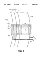
- FIG. 3 illustrates a CCD/TDI used as a portion of a pickup assembly
- FIG. 4 is a block diagram of a virtual tracking system in constructed in accordance with the principles and methods of the present invention.
- FIGS. 5A and 5B are, respectively, an illustrative point spread functions for pixels of an image detector of an optical disk reader and illustrative pattern of the cross-talk between neighboring pixels;
- FIGS. 6A and 6B illustrate the effects of between track nulling in accordance with the principles of the present invention
- FIG. 7 is an illustrative embodiment of circuitry for performing between track nulling
- FIGS. 8 and 9 are illustrative block diagram schematics of two embodiments of the pixel selector of FIG. 4, for an optical disk having low and high track densities, respectively;
- FIG. 10 is a block diagram of circuitry for extracting data from the signals output by the pixel selector of FIG. 4;
- FIGS. 11 and 12 are, respectively, a block diagram providing more detail of the clock circuitry of FIG. 10 and a block diagram of the digital PLL circuitry of the front end circuitry of FIG. 10;
- FIG. 13 is a block diagram of the front end circuitry of FIG. 10.
- FIG. 14 is a flow chart outlining illustrative processes for reading a requested block of data from an optical disk and providing the requested block of data to a host processor.
- FIG. 1 a brief description of the components and operation of a previously known optical disk reader 10 is described with respect to FIG. 1.
- the detailed description of the design and operation of such previously known optical disk readers may be found, for example, in Compact Disk Technology, H. Nakajima and H. Ogawa, published by Ohmsha, Ltd., Japan (1992), translated by Aschmann, C., IOS Press, Inc., Burke, Va., and The Compact Disk Handbook, Ken C. Pohlmann (2nd Ed. 1992), A-R Editions, Inc., Madison, Wis., both of which are incorporated herein in their entirety by this reference.
- the present invention is then described where it differs in major respects from the previously known system of FIG. 1.
- FIG. 1 is merely illustrative of the various types of optical disk apparatus in which the methods and apparatus of the present invention may be employed.
- the invention described herein may be advantageously employed in any of the MMCD, SD, or DVD systems currently under development.
- various features of the present invention may be fully and independently integrated into any of the optical disk systems previously known or now under development. To facilitate this understanding, the following description is provided with subheadings that refer to particular features that may be used individually or in combination.
- Illustrative previously known optical disk reader 10 comprises a spindle motor 14 that rotates optical disk 100 at high speed and pickup 16 including an illumination source and a photodetector for generating electrical signals representative of information-bearing pits formed a reflective surface within optical disk 100.
- the electrical signals from the photodetector of pickup 100 are then passed to front end 22 and fourteen-to-eight demodulation circuitry 24, and under the control of controller 38, to Cross Interleaved Reed-Solomon Code circuitry 26, error correction code circuitry 30, subcode circuitry 25 and buffer 32.
- Controller 38 controls focus and tracking circuitry 18 and interface 36.
- the electrical signals may be processed into suitable analog signals (using circuitry not shown) connected to audio means 28, while for computer applications, the electrical signals are typically transferred from buffer 32 to host processor 34 via interface 36.
- Spindle motor 14 spins optical disk 100 at a speed that depends upon the radial location of pickup head 16 (for example, for a 1X CD-ROM spindle speed, approximately 200-500 RPM), to maintain a constant linear velocity of an optical disk track relative to pickup head 16. For a CD-ROM format, this linear velocity is generally 1.4 m/s, while for the proposed MMCD format it approaches 4 m/s.
- Pickup assembly 16 typically includes a laser diode that illuminates only a single data track on optical disk 100 and an optical sensor onto which an image reflected from the optical disk is projected.
- the intensity, or other property, of the light beam reflected from the surface of optical disk 100 is modulated by inhomogeneities in the reflective surface of the optical disk (i.e., bumps or pits, referred to hereinafter as "data spots") arranged in spiral or circular tracks on optical disk 100.
- Pickup assembly 16 includes circuitry to generate an electronic signal representative of the modulation in the illumination impinging upon its optical sensor due to the present of the data spots. To ensure that the laser illumination remains focussed on the reflective surface of optical disk 100, pickup assembly 16 also provides signals to focus and tracking subsystem 18.
- the data spots are recorded on optical disk 100 using a modulation code that permits a data clock to be recovered from as the data is read off of the optical disk.
- Phase-locked-loop (PLL) circuitry 20 recovers the data clock from, and maintains the data clock in synchrony with, the modulated electronic signal from pickup assembly 16.
- the data clock is representative of the linear velocity of the data track relative to pickup assembly 16 and may be used as a feedback signal to control the speed of spindle motor 14 to maintain a constant linear velocity.
- Front end circuitry 22 uses the data clock from PLL 20 to recover a serial stream of bits from the electronic signal.
- Front end circuitry 22 contains additional circuitry to identify synchronization codes in the bit stream so that the serial bit stream may be correctly assembled into multi-bit data words which are transferred to demodulation circuitry 24.
- Demodulation circuitry 24 may be programmed for fourteen-to-eight demodulation (EFM), eight-to-fifteen demodulation (as in the SD systems), eight-to sixteen demodulation (EFM Plus), or use another suitable demodulation scheme.
- demodulated data words, or symbols are then assembled into blocks and decoded CIRC decoder 26 using a form of Cross Interleaved Read-Solomon code, for example, CIRC for CD-formats and CIRC Plus for DVD.
- Demodulated data words are also provided to subcode processor 25 which extracts data, such as block numbers, or song titles, which are recorded in subcode channels embedded in each block of data words.
- the data from CIRC decoder 26 represents, in digital form, the video or audio signal that was originally recorded and stored on the disk. These signals may then be converted to analog signals and the original recorded signal reproduced using conventional audio or video devices 28. Errors in the recovered audio or video signals are handled by interpolation and filtering circuitry (not shown) to calculate a value to use in place of the erroneous data. Because of the interpolation process, isolated errors in an audio or video signal are unlikely to be noticed when listening to the audio or viewing the video signals.
- ECC error correction codes
- the rate of data transfer between the optical disk itself and the host processor is limited by the rate at which the data can be processed by the circuitries shown in FIG. 1.
- the data rate of the signal being read from the optical disk is about 4.32 MHz, well within the processing capabilities of the electronic circuits involved.
- the data transfer rate is limited by the speed at which the data can be read off the disk.
- FIG. 2 an optical disk reader is described that provides a high data transfer rate, in accordance with the principles of the present invention, by reading multiple tracks of data from an optical disk simultaneously.
- Much of the circuitry of FIG. 2 may be common to or readily adapted from the circuitry of the system of FIG. 1. Accordingly, the following description describes in detail the differences between a previously known optical disk reader and apparatus constructed in accordance with the principles of the present invention.
- apparatus constructed in accordance with the present invention may include the following features: (i) a Virtual Tracking System (VTS); (ii) circuitry for reducing cross-talk in the data signals generated for neighboring tracks of an optical disk; (iii) phase-lock loop circuitry that permits a clock associated with a reference track to be used for synchronizing the recovery of data from neighboring tracks; and (iv) a parallel write/asynchronous read architecture that enables blocks of data to be read from the optical disk, processed and written to a buffer in parallel while being asynchronously retrieved from the buffer by a host computer.
- VTS Virtual Tracking System
- circuitry for reducing cross-talk in the data signals generated for neighboring tracks of an optical disk
- phase-lock loop circuitry that permits a clock associated with a reference track to be used for synchronizing the recovery of data from neighboring tracks
- a parallel write/asynchronous read architecture that enables blocks of data to be read from the optical disk, processed and written to a buffer in parallel while being asynchronously retrieved from
- Apparatus 10' of FIG. 2 includes pickup assembly 16 having a source of wide-area illumination, as described, for example, in commonly assigned U.S. Pat. No. 5,426,623, and in copending, commonly assigned U.S. patent application Ser. No. 08/315,432, that illuminates multiple adjacent tracks of data spots on the reflective surface of optical disk 100.
- Pickup assembly further includes an array of optical sensors, such as the time delay integration/charge coupled device (TDI/CCD) described in commonly assigned U.S. Pat. No. 5,426,623, that receives light reflected from the multiple adjacent data tracks and generates in parallel electrical signals representative of the data spots in the multiple adjacent data tracks of optical disk 100.
- TTI/CCD time delay integration/charge coupled device
- VTS 54 analyzes the electrical signals output from the array of optical sensors and selects certain of those electrical signals for further processing by subsequent blocks of circuitry of apparatus 10'.
- Front end circuitry 56 performs a function similar to that of front end circuitry 22 of FIG. 1, except that multiple bit streams are processed concurrently, so additional circuitry is provided for buffering and synchronizing data transfers to subsequent processing circuitry.
- Front end circuitry 56 also includes a multiplexer for routing multiple data streams to demodulation circuitry 24.
- Memory 58 is provided to buffer the data read from the multiple data tracks, and to decouple the process of reading data from optical disk 100 from the process of transferring the data to host processor 34. Memory 58 therefor is large enough to hold about as many data blocks from multiple data tracks of optical disk 100 as can be read in one revolution of optical disk 100. Controller 38 maps data from the multiple data tracks to memory 58 so that individual data blocks will be correctly assembled without overwriting one another. As will be appreciated by those of skill in the art of buffer design, this mapping may be either dynamic or static.
- Track arcs 101 comprise segments of a single spiral track on optical disk 100, or alternatively arcs 101 may be segments of adjacent concentric tracks. Shown superimposed over track segments 101 is optical pickup 60 including detector matrix 62, a charge-coupled device (CCD), which preferably comprises a rectangular array of cells, or pixels, configured for time delay and integration (TDI).
- CCD charge-coupled device
- TDI time delay and integration
- Detector matrix 62 is constructed so that a clocking signal applied to detector matrix 62 causes the charge accumulated in pixel 62a to be transferred to the next pixel in a column of pixels, for example from pixel 62a to pixel 62b. Successive clocking signals applied to detector matrix 62 therefor cause the accumulated charge to be transferred to successive pixels in a column of pixels.
- the clock signals are preferably applied to detector matrix 62 at a rate so that the charge is transferred down a row of pixels at rate corresponding to the linear speed of the tracks passing below the detector matrix.
- Sensing lines 64 read the accumulated charge that is transferred out of the last row of pixels 62n and provides electrical signals proportional to the intensity of the light reflected from optical disk 100, as modulated by the data spots contained in tracks 101.
- a sample and hold circuit may be advantageously used for reading the accumulated charge on the last row of pixels 62n, so as to reduce noise that may be generated by the reset signal supplied to detector matrix 62.
- the number and spacing of the pixel columns is related to the track pitch of the optical disk, the number of tracks to be read at once, and the density of the CCD pixels. For example, to read ten tracks spaced 1.6 ⁇ m apart with a detector matrix having pixels imaged approximately 0.4 ⁇ m apart would require approximately
- detector matrix 62 includes 64 columns of pixels, which is sufficient to span approximately 16 tracks of an optical disk, even though data from only ten tracks is actually selected for processing.
- extra pixels provide for electronic correction of fine tracking errors, while electromechanical tracking of the disk tracks may be used to account for large variations in track positioning, for example, due to eccentricity of the optical disk.
- VTS 70 selects from signal lines 64 (see FIG. 3) of detector matrix 62 those signal lines which correspond to pixel columns for which the electrical signals representative of the data in the optical disk tracks is to be further processed.
- signal lines 64 see FIG. 3
- detector matrix 62 selects from signal lines 64 (see FIG. 3) of detector matrix 62 those signal lines which correspond to pixel columns for which the electrical signals representative of the data in the optical disk tracks is to be further processed.
- the optical response of a pixel of detector matrix 62 is typically not uniform, but instead manifests a Gaussian point spread function, as shown in FIG. 5A.
- row 62m of detector matrix 62 of FIG. 3 Also shown in FIG. 5A is row 62m of detector matrix 62 of FIG. 3, and how the centers of tracks T i-1 , T i and T i+1 align with the pixels in row 62m.
- the charge accumulated by each pixel of row 62m is proportional to the intensity of the illumination received by that pixel, in accordance with the point spread functions illustratively shown in FIG. 5A.
- pixel P j which is centered over track T i , receives the largest amount of illumination reflected from track T i , while also receiving illumination from tracks T i-1 , and T i+1 , in accordance with above-illustrated pixel point spread function.
- Pixels P j+4 are illustratively centered over tracks adjacent to track T i and also receive some illumination contribution from track T i . Each pixel therefore receives some illumination contribution from multiple neighboring tracks on the optical disk, an effect referred to as cross-talk.
- Optical disk apparatus constructed in accordance with the principles of the present invention utilizes the shape of the illumination patterns projected onto the pixels of the detector matrix to locate the centers of the disk tracks, and to select which pixels to use to retrieve data from the tracks.
- VTS 70 includes circuitry for performing a between track nulling function, a squaring function 74, an integration function 76, a sampling function 78 and a track computation function 80.
- the outputs of the track position computation function are feed to a pixel select multiplexer 82 that selects only a subset of the electrical signals generated by detector matrix 62 for further processing.
- VTS 70 receives signals from detector matrix 62 and processes those signals to substantially null, or minimize, the "between track" signals, i.e. from pixels receiving illumination from the reflective portions of optical disk 100 where there are no data spots.
- Applicants have determined that subtracting from each pixel signal a weighted sum of the signals of neighboring pixels is effective for defining the track boundaries. In one preferred embodiment, the formula:
- the processed signals are then squared by squaring function 74 to obtain signals related to the total illumination energy received by each pixel, and integrated at function block 76 to smooth the signals and average out the high frequency modulation caused by the presence of the data spots in the light reflected from optical disk 100.
- An integration period of between approximately 2 microseconds and 10 milliseconds, depending upon the spindle speed, is expected to provide satisfactory operation of VTS 70.
- the integrated signals output by integration function 76 are then time division multiplexed and sampled by sampling function 78 to produce a digital signal, referred to as a "manhattan signal" (because of its similarity to the New York skyline).
- Illustrative digital signals output by sampling function 78 are shown in FIGS. 6A and 6B, in which each "step" 90 in the signal corresponds to a separately processed signal from a column of pixels in detector matrix 62 after integration.
- a dedicated CCD tracking element such as described in concurrently filed, co-pending and commonly assigned U.S. patent application Ser. No. (ZRI-003), which is incorporated herein by reference in its entirety, may be used to provide the input to sampling function 78.
- Track position computation function 80 processes the Manhattan signal output by sampling function 78 using oversampling techniques to locate the minima in the signal to subpixel accuracy. Because between track nulling function 72 substantially cancels out the signals for pixels reading the illumination from between track areas of the optical disk, the minima in the Manhattan signal correspond to the centers of the between track areas, and thus the locations of the data tracks may be calculated. Based on the track position calculations, track position computation function 80 provides signals to pixel select circuitry 82, to select those pixel signals 64 which correspond to the tracks which are desired to be read.
- circuitry block 95 which includes operational amplifiers configured as difference amplifiers.
- Circuit block 95 receives as inputs the signals from pixel P j and its P j-2 and P j+2 neighboring pixels.
- Operational amplifier 110 is coupled to resistors 112, 114, 116, and 118 to form a difference amplifier which calculates an output voltage V o according to:
- resistors 112, 114, 116, and 118 may then be chosen to approximate equation (1).
- the output of the difference amplifier is squared by multiplier 120 and then integrated by an integrating amplifier comprising operational amplifier 122, resistor 124, and feedback capacitor 126.
- Circuitry blocks 96, 97, 98, etc. contain replications of the circuitry of block 95, as described hereinabove, as needed to perform between track nulling for all of the pixel signals output by detector matrix 62.
- the outputs of circuits 95, 96, 97, 98, etc. are then multiplexed into a single signal by analog multiplexer 128 and digitized by analog-to-digital converter (ADC) 130 to produce the Manhattan signal.
- ADC analog-to-digital converter
- track position computation function 80 then computes the positions of the data tracks--and identifies the corresponding pixel signals therefor--by processing the Manhattan signal output by ADC 130.
- This track position computation function may be performed, for example, using a digital signal processor (DSP), that reads digital samples from ADC 130, and using oversampling techniques, filters the sampled data to remove high frequency noise introduced by the multiplexing and sampling process.
- DSP digital signal processor
- Track position computation function 80 outputs to pixel selector 82 the track positions as pixel select signals, and optional cross-talk cancellation coefficients, described below.
- pixel selector 82 includes one switch 132 for each output line 132. Each switch 132 routes a selected one of the signals on its inputs to its output. The input pixel signals to be output by switches 132 is controlled by the pixel select signals from track position computation function 80, so that pixel signals corresponding to track data will always be selected.
- Pixel selector 82 may employ multiple stages to reduce the complexity and cost of the multiplexer architecture. For example, in one preferred embodiment of pixel selector 82 for handling 64 sensing lines from detector matrix 62, a two-stage multiplexer is employed having a first stage of thirty-two 2:1 multiplexers followed by a second stage having fourteen 15:1 multiplexers. Alternatively, the second stage may include sixteen multiplexers if the first stage multiplexers are smaller.
- the track position computation function 80 adjusts the pixel select signals so that switches 132 continually select the pixel signals that correspond to desired disk tracks. This process provides a method of tracking desired disk tracks electronically for relatively small radial movements of the data track, without repositioning the pickup assembly. Of course, larger radial movement of the disk tracks also may be accommodated by electromechanical movement of the pickup head.
- the output signal of each switch 132 is filtered by low-pass (LP) filters 134, preferably fourth-order LP filters, to remove noise and switching artifacts from the signals before further processing.
- LP low-pass
- the intensity of the illumination received by a pixel includes a cross-talk component representing illumination from adjacent tracks.
- the cross-talk illumination may be sufficiently small that the disk may be read accurately without the need for cross-talk cancellation.
- cross-talk may become severe when attempting to simultaneously read multiple adjacent tracks and interfere with accurate disk reading. Accordingly, cross-talk cancellation may be required to reliably read high density optical disks.
- FIG. 9 illustrates one embodiment of pixel selector 82 which includes optional cross-talk cancellation circuitry suitable for high density optical disks.
- a plurality of switches 132 select pixel signals as determined by track position computation function 80. While calculating track positions and determining the pixel select signals, track position computation function 80 also determines cross-talk cancellation coefficients, ⁇ and ⁇ . Cross-talk cancellation coefficients ⁇ and ⁇ are based upon the distance from the center of a selected pixel to the center of the disk tracks on either side of the pixel.
- Track position computation function 80 may either calculate the values of ⁇ and ⁇ , or, alternatively, may look up the values of ⁇ and ⁇ in a coefficient look up table, stored for example, in ROM.
- Multiplying Digital-to-Analog Converters (MDAC) 133 use the values of ⁇ or ⁇ provided by track position computation function 80 to scale the signals output by switches 132.
- the scaled and unscaled pixel signals, S m and S m ⁇ 1, respectively, are summed at block 135 according to the formula:
- each track data signal T m output, for example, by VTS 70 or a dedicated CCD-tracking detector, as described in the above-incorporated application in conjunction with a suitable pixel selector 82, is processed by front end circuitry 140.
- Front end circuitry 140 converts the modulated track data signal to a parallel data word.
- Clock circuitry 142 generates a reference clock from a selected track data signal, the reference track signal. The reference clock is sent to front end circuitries 140 and is used to extract data existing in the modulation of the track data signals, as described hereinbelow.
- clock circuitry 142 comprises a phase-locked loop and includes voltage controlled oscillator (VCO) 144 for generating a fast clock signal, ⁇ fast , having a frequency that is a multiple of the data rate (frequency) of the reference track data signal.
- VCO voltage controlled oscillator
- Divider/counter 146 reduces the frequency of the signal output by VCO 144 to generate a data clock signal, ⁇ data , having a frequency nearly the same as that of the track data signal.
- An error signal which indicates the difference between the data clock frequency and the track data frequency is generated by phase detection circuitry 148, the error signal being proportional to the phase difference between the data clock signal and the reference track data signal.
- the error signal is then integrated and filtered by filter block 150 to produce a voltage signal corresponding to the desired frequency of the output signal of VCO 144.
- phase difference between the track data and the data clock will increase.
- This increase in phase difference is detected by phase detection circuitry 148, and converted into an error signal that is filtered by low pass filter 150 to produce a voltage that causes VCO 144 to generate a signal having a lower frequency.
- the data clock generated by the circuitry of FIG. 11 has a frequency and phase which are correct for the reference track data signal.
- the corresponding track data signals differ slightly in frequency and may differ substantially in phase.
- Front end circuitry 140 of FIG. 10 therefore includes circuitry for correcting the phase and frequency of the system data clock ⁇ data .
- Digital PLL circuitry 152 of front end circuitry 140 corrects the phase and frequency of system data clock to match that of the track data signals.
- Fast clock signal ⁇ fast is used as the clock input to shift register 154, which is configured as a ring counter.
- Shift register 154 is loaded with a bit pattern having only a single bit which is set, for example 01000000 2 , the remaining bits being cleared.
- Each pulse of fast clock ⁇ fast causes the bit pattern in shift register 154 to shift one bit position, or cell.
- a bit which is shifted out the end of shift register 154 is "wrapped around" and shifted back in at the other end of the shift register.
- the single set bit in shift register 154 circulates through each cell in the register at a frequency determined by fast clock ⁇ fast .
- each cell in shift register 154 is input to multiplexer 156, which functions to output the value of a selected one of the shift register cells.
- the combination of shift register 154 and multiplexer 156 functions to divide the frequency of fast clock ⁇ fast by the number of bits in the shift register to produce track clock ⁇ track . For example, if shift register 154 were to have eight bits, each bit position would have a ⁇ 1 ⁇ bit in it only once every eight pulses of the fast clock. Thus if multiplexer 156 were to selectively output the value of bit three of shift register 154, the output of the multiplexer would be a ⁇ 1 ⁇ whenever there was a ⁇ 1 ⁇ in bit position three of the shift register, i.e. once every eight pulses of fast clock ⁇ fast .
- Edge detector 158 generates a pulse on every edge, i.e. high-low or low-high transition, of the track data signal.
- Phase detector 160 determines the phase relationship between the occurrence of pulses of track clock ⁇ track output by multiplexer 154 and pulses from edge detector 158. Ideally, an edge pulse from edge detector 158 should occur midway between successive pulse of track clock ⁇ track . An edge pulse which occurs early indicates that the track clock is slow, and conversely a late edge pulse indicates the track clock is fast.
- the output of phase detector 160 indicates the position of an edge pulse relative to the midpoint between successive track clock pulses.
- Error accumulator 162 monitors and accumulates the error signal from phase detector 160, and filters the error signal to reduce the effects of jitter between the clock and edge pulses.
- selector 164 adjusts the phase of track clock ⁇ track by causing multiplexer 156 to select a different input to pass through to its output. Changing the multiplexer's input either inserts or removes a small amount of time to the interval from one track clock pulse to the next such pulse. For example, if shift register 154 has eight bits and is designed to shift bits to the right, and if selector 164 causes multiplexer 156 to change its input from bit position three to bit position four, the next pulse output by multiplexer 156 will occur on the seventh fast clock pulse instead of the eighth. Conversely, changing the multiplexer's input from bit position three to bit position two will cause a track clock pulse to occur on the ninth fast clock pulse. Thus by changing the bit selected by multiplexer 156, the phase and frequency differences between the reference track data signal and another track data signal can be corrected.
- selector 164 includes logic to prevent selection of a different input by the multiplexer at an inopportune time. For example, if multiplexer 156 is reading bit position 6 of shift register 154, a ⁇ 1 ⁇ is in bit position five, and shift register 154 shifts right (i.e. the ⁇ 1 ⁇ in bit position six moves to bit position five) at the same instant selector 164 switches the input of multiplexer 156 from bit position five to bit position six, a clock pulse will be missed, and a data bit will not be sampled correctly.
- selector 164 monitors the output of shift register 154 to avoid the occurrence of situations which may lead to data corruption.
- Digital PLL 152 described in reference to FIG. 12, is used to sample the track data signal and generate a stream of bits.
- the bit stream is monitored by synchronization detector circuitry 170 to determine the beginning of a data block.
- the serial bit stream is also shifted into shift register 172 to accumulate bits into data words or symbols.
- Control logic 174 is synchronized with a data block by a signal from synchronization detector 170. When a complete data word is assembled in shift register 172, control logic 174 causes the data word to be read into first-in, first-out (FIFO) buffer 176 where it is retrieved by demodulation circuitry 24 of FIG. 2. As will of course be apparent, the circuitry of FIG. 13 may be readily modified for use with other optical disk formats, for example, the proposed MMCD, SD and DVD formats.
- FIGS. 2 and 14 illustrative processes for reading and writing blocks of data in parallel from the optical disk to a buffer and for reading a block of data requested by host processor 34 are described.
- the process of providing a data block to a host processor is split into two asynchronous processes illustrated by flowcharts 180 and 200, corresponding, respectively, to reading data from the disk and the process of providing the data to the host processor.
- Process 180 is entered, at 182, with a request to read a total of k data blocks starting at block n.
- controller 38 calculates, or looks up in a table, the track t which contains data block n, and, if required, positions the pickup assembly to read track t as well as several adjacent tracks.
- a desired number of data blocks are read in parallel from optical disk 100 and stored in buffer 58.
- a Block Address Table is updated to reflect the block numbers currently stored in the buffer. If at step 190 it is determined that all k data blocks have not been read, a new starting block is determined (step 194), and the pickup assembly is repositioned (step 192).
- Data reading process 180 terminates when all of the requested data has been read and transferred to buffer 58.
- the process of flowchart 200 is performed concurrently with the process of flowchart 180. This process is entered when the host processor requests k data blocks beginning at block n. Upon receiving this request, controller 38 first determines at block 206 whether the data block is already in buffer 58 by consulting the Block Address Table. If the data block is present, then the data block is retrieved from buffer 58 and transferred to host processor 34. If the data block has not been read yet, the process of flowchart 180 is initiated to read the desired block while process 200 waits for the data to become available in buffer 58. These steps are repeated as necessary until the last block of the requested data has been transferred to the host processor.
- buffer 58 is capable of holding the data for about one full revolution of optical disk 100.
Landscapes
- Engineering & Computer Science (AREA)
- Signal Processing (AREA)
- Physics & Mathematics (AREA)
- Optics & Photonics (AREA)
- Optical Recording Or Reproduction (AREA)
Abstract
Description
(10*1.6)/0.4 μm=40 pixels.
P.sub.out(j) =P.sub.in(j) -a(P.sub.in(j-2) +P.sub.in(j+2)) (1)
______________________________________
P.sub.in(i) is the unprocessed signal from pixel i;
P.sub.out(j)
            is the processed signal from pixel j;
            and
a           is a constant between about 0.15 and
            0.5, and preferably about 0.35,
______________________________________
V.sub.o =V.sub.n (1+R.sub.118 /R.sub.116)-R.sub.118 (V.sub.n-2 /R.sub.112 +V.sub.n+2 /R.sub.114). (2)
T.sub.m =S.sub.m -αS.sub.m-1 -βS.sub.m+1 (3)
Claims (24)
Priority Applications (8)
| Application Number | Priority Date | Filing Date | Title |
|---|---|---|---|
| US08/559,429 US5627805A (en) | 1995-11-15 | 1995-11-15 | Methods and apparatus for high speed optical storage device |
| PCT/EP1996/004970 WO1997018561A2 (en) | 1995-11-15 | 1996-11-13 | Mehods and apparatus for high speed optical storage device |
| AU76837/96A AU7683796A (en) | 1995-11-15 | 1996-11-13 | Mehods and apparatus for high speed optical storage device |
| US08/804,105 US5907526A (en) | 1995-11-15 | 1997-02-20 | Methods and apparatus for simultaneously reading multiple tracks of an optical storage medium |
| US08/801,397 US5793549A (en) | 1995-11-15 | 1997-02-20 | Methods and apparatus for synchronizing read out of data from multiple tracks of an optical storage device |
| US09/013,861 US6028827A (en) | 1995-11-15 | 1998-01-27 | Methods and apparatus for synchronizing read out of data from multiple tracks of an optical storage device |
| US09/013,864 US6381210B1 (en) | 1995-11-15 | 1998-01-27 | Methods and apparatus for concurrently processing data from multiple tracks of an optical storage medium |
| US09/203,294 US6111831A (en) | 1995-11-15 | 1998-12-01 | Methods and apparatus for simultaneously reading multiple tracks of an optical storage medium |
Applications Claiming Priority (1)
| Application Number | Priority Date | Filing Date | Title |
|---|---|---|---|
| US08/559,429 US5627805A (en) | 1995-11-15 | 1995-11-15 | Methods and apparatus for high speed optical storage device |
Related Child Applications (2)
| Application Number | Title | Priority Date | Filing Date |
|---|---|---|---|
| US08/801,397 Continuation-In-Part US5793549A (en) | 1995-11-15 | 1997-02-20 | Methods and apparatus for synchronizing read out of data from multiple tracks of an optical storage device |
| US08/804,105 Continuation-In-Part US5907526A (en) | 1995-11-15 | 1997-02-20 | Methods and apparatus for simultaneously reading multiple tracks of an optical storage medium |
Publications (1)
| Publication Number | Publication Date |
|---|---|
| US5627805A true US5627805A (en) | 1997-05-06 |
Family
ID=24233569
Family Applications (1)
| Application Number | Title | Priority Date | Filing Date |
|---|---|---|---|
| US08/559,429 Expired - Lifetime US5627805A (en) | 1995-11-15 | 1995-11-15 | Methods and apparatus for high speed optical storage device |
Country Status (3)
| Country | Link |
|---|---|
| US (1) | US5627805A (en) |
| AU (1) | AU7683796A (en) |
| WO (1) | WO1997018561A2 (en) |
Cited By (25)
| Publication number | Priority date | Publication date | Assignee | Title |
|---|---|---|---|---|
| WO1998037554A2 (en) * | 1997-02-20 | 1998-08-27 | Zen Research N.V. | Methods and apparatus for synchronously reading multiple tracks of an optical storage medium using multiple reading beams |
| US5870227A (en) * | 1997-03-13 | 1999-02-09 | T Squared G Systems, Inc. | Scanning head lens assembly |
| US5974012A (en) * | 1996-08-20 | 1999-10-26 | Sony Corporation | Recording/reproducing apparatus and recording medium rotation control method |
| US5982726A (en) * | 1996-10-19 | 1999-11-09 | Lg Electronics, Inc. | Multi-rate optical disc recording and reproducing apparatus |
| US5986989A (en) * | 1996-09-23 | 1999-11-16 | Deutsche Thomson-Brandt Gmbh | Method for processing the output signals of an optoelectronic scanner in a replay or recording appliance, and a corresponding appliance |
| US6028827A (en) * | 1995-11-15 | 2000-02-22 | Zen Research N.V. | Methods and apparatus for synchronizing read out of data from multiple tracks of an optical storage device |
| US6137763A (en) * | 1998-09-24 | 2000-10-24 | Zen Research N.V. | Method and apparatus for buffering data in a multi-beam optical disk reader |
| WO2001018808A1 (en) * | 1999-09-03 | 2001-03-15 | Zen Research (Ireland), Ltd. | Digital read channel for optical disk reader |
| US6252715B1 (en) * | 1997-03-13 | 2001-06-26 | T. Squared G, Inc. | Beam pattern contractor and focus element, method and apparatus |
| US6314071B1 (en) | 1998-02-20 | 2001-11-06 | Zen Research (Ireland), Ltd. | Method and apparatus for reading multiple tracks and writing at least one track of an optical disk |
| US6341112B1 (en) | 1996-10-19 | 2002-01-22 | Lg Electronics Inc. | Multi-rate optical disc recording and reproducing apparatus |
| US6381210B1 (en) * | 1995-11-15 | 2002-04-30 | Zen Research (Ireland) Ltd. | Methods and apparatus for concurrently processing data from multiple tracks of an optical storage medium |
| US20020080707A1 (en) * | 2000-12-22 | 2002-06-27 | Matsushita Electric Industrial Co., Ltd. | Optical disk control device |
| WO2002071400A2 (en) * | 2001-03-05 | 2002-09-12 | Zen Research (Ireland), Ltd. | Multi-element detector and multi-channel signal conditioner for use reading multiple tracks of optical disks having diverse formats |
| US6515610B1 (en) | 2001-11-19 | 2003-02-04 | Cirrus Logic, Inc. | Analog-to-digital conversion for multiple voltage signals in an integrated circuit |
| US20030076760A1 (en) * | 2001-10-23 | 2003-04-24 | Koby Finkelstein | Methods and apparatus for cross-talk and jitter reduction in multi-beam optical disks |
| US6781948B2 (en) * | 1998-02-26 | 2004-08-24 | Deutsche Thomson-Brandt Gmbh | Device for reading from and/or writing to optical recording media |
| US20040208108A1 (en) * | 2003-04-18 | 2004-10-21 | Lucere, Lp | Apparatus for creating a multi-dimensional data signal |
| US20050053260A1 (en) * | 1999-08-23 | 2005-03-10 | Worthington Mark O. | Methods and apparatus for analyzing operational and analyte data acquired from optical discs |
| US6891791B1 (en) | 1999-08-19 | 2005-05-10 | Interscience, Inc. | Optical pickup apparatus and method |
| US20060072401A1 (en) * | 2004-09-30 | 2006-04-06 | Hanks Darwin M | Optical data processing |
| US20060072425A1 (en) * | 2004-09-30 | 2006-04-06 | Hanks Darwin M | Array-based optical head |
| WO2006041492A1 (en) * | 2004-10-08 | 2006-04-20 | Scratchbuster Inc. | Disk restoration service vending machine |
| US20090097377A1 (en) * | 2006-04-10 | 2009-04-16 | Mempile Inc. | Secured Optical Information Carrier, and Data Encryption Method and Apparatus for Recording Data in the Optical Information Carrier |
| US20090279393A1 (en) * | 2008-05-09 | 2009-11-12 | Apple Inc. | Playing data from an optical media drive |
Citations (27)
| Publication number | Priority date | Publication date | Assignee | Title |
|---|---|---|---|---|
| US4460988A (en) * | 1980-10-20 | 1984-07-17 | At&T Bell Laboratories | Data accessing system for optical disk mass memory |
| US4486870A (en) * | 1981-07-23 | 1984-12-04 | Pettigrew Robert M | Optical data storage |
| US4536866A (en) * | 1978-11-30 | 1985-08-20 | Videonics Of Hawaii, Inc. | Information retrieval system and apparatus |
| US4646280A (en) * | 1984-02-20 | 1987-02-24 | Sony Corporation | Optical disk record player with fast access time |
| US4839876A (en) * | 1987-11-23 | 1989-06-13 | International Business Machines Corporation | Track seeking using a track following loop |
| US4918676A (en) * | 1987-07-31 | 1990-04-17 | Kabushiki Kaisha Toshiba | Track accessing apparatus for optical disk |
| US4972396A (en) * | 1988-10-24 | 1990-11-20 | Honeywell Inc. | Multiple independently positionable recording-reading head disk system |
| US4980376A (en) * | 1985-05-30 | 1990-12-25 | Istituto Guido Donegani S.P.A. | Benzoyl-ureas having insecticide activity |
| US4989190A (en) * | 1987-07-20 | 1991-01-29 | Oki Electric Industry Co., Ltd. | Apparatus for seeking a track of an optical disk in which information is recorded |
| US5001732A (en) * | 1989-01-10 | 1991-03-19 | Sharp Kabushiki Kaisha | Track counter for optical disk |
| US5081617A (en) * | 1990-09-24 | 1992-01-14 | Creo Products Inc. | Optical system for simultaneous reading of multiple data tracks |
| US5111445A (en) * | 1989-11-17 | 1992-05-05 | Sony Corporation | Holographic information storage system |
| US5128919A (en) * | 1987-11-16 | 1992-07-07 | Sony Corporation | Apparatus for reproducing an optically recorded information |
| US5150347A (en) * | 1989-03-14 | 1992-09-22 | Fujitsu Limited | Beam track position control apparatus for optical disk apparatus |
| US5199017A (en) * | 1991-09-11 | 1993-03-30 | International Business Machines Corporation | Optical disk drive and method for counting the number of tracks on an optical disk |
| US5210726A (en) * | 1992-02-07 | 1993-05-11 | Maxoptix Corporation | Track seek method utilizing an ideal signal |
| US5233583A (en) * | 1990-12-19 | 1993-08-03 | General Electric Company | Tracking and reading system for an optical medium and medium for use therewith |
| US5239530A (en) * | 1989-04-19 | 1993-08-24 | Tokyo Shibaura Electric Co | Method and apparatus for detecting a track count in an optical disk apparatus for recording/reproducing data on/from an optical disk |
| US5245597A (en) * | 1990-09-29 | 1993-09-14 | Samsung Electronics Co., Ltd. | Method and device for correcting track deviation in optical disc drive |
| US5274507A (en) * | 1991-09-09 | 1993-12-28 | Paul Lee | Parallel data encoding for moving media |
| US5295125A (en) * | 1992-02-03 | 1994-03-15 | Hitachi, Ltd. | Optical head device for recording/reproduction for recording medium using plural light spots |
| US5301174A (en) * | 1989-07-14 | 1994-04-05 | Sharp Kabushiki Kaisha | Optical disk recording and reproducing apparatus |
| US5313448A (en) * | 1991-06-28 | 1994-05-17 | Hitachi, Ltd. | Laser device driven by a periodic waveform optimized for reducing laser noise |
| US5361245A (en) * | 1992-07-13 | 1994-11-01 | Kabushiki Kaisha Toshiba | Optical signal processing apparatus for detecting the direction of movement of an optical reading device relative to an optical disk |
| US5394386A (en) * | 1993-01-29 | 1995-02-28 | Samsung Eectronics Co., Ltd. | Optical disk high-speed search control device |
| US5426623A (en) * | 1992-04-10 | 1995-06-20 | Alon; Amir | Method for acquiring the track data from a multiple track image and optical disk |
| US5465244A (en) * | 1991-03-28 | 1995-11-07 | Kabushiki Kaisha Toshiba | Disc reproducing apparatus |
Family Cites Families (5)
| Publication number | Priority date | Publication date | Assignee | Title |
|---|---|---|---|---|
| US4583211A (en) * | 1982-06-15 | 1986-04-15 | Tokyo Shibaura Denki Kabushiki Kaisha | Frequency detecting circuit for digital information reproducing system |
| JPH0213150A (en) * | 1988-06-30 | 1990-01-17 | Pioneer Electron Corp | Demodulation clock generating circuit |
| JP2721228B2 (en) * | 1989-03-01 | 1998-03-04 | 株式会社東芝 | Information recording device |
| US5377178A (en) * | 1991-10-11 | 1994-12-27 | Hitachi, Ltd. | Data recording/reproducing method and apparatus using a recording medium having clock marks recorded in a wobbled track for read/write synchronization |
| US5402399A (en) * | 1992-08-31 | 1995-03-28 | Olympus Optical Co., Ltd. | Apparatus and method for reproducing information data from optical cards |
-
1995
- 1995-11-15 US US08/559,429 patent/US5627805A/en not_active Expired - Lifetime
-
1996
- 1996-11-13 WO PCT/EP1996/004970 patent/WO1997018561A2/en active Application Filing
- 1996-11-13 AU AU76837/96A patent/AU7683796A/en not_active Abandoned
Patent Citations (27)
| Publication number | Priority date | Publication date | Assignee | Title |
|---|---|---|---|---|
| US4536866A (en) * | 1978-11-30 | 1985-08-20 | Videonics Of Hawaii, Inc. | Information retrieval system and apparatus |
| US4460988A (en) * | 1980-10-20 | 1984-07-17 | At&T Bell Laboratories | Data accessing system for optical disk mass memory |
| US4486870A (en) * | 1981-07-23 | 1984-12-04 | Pettigrew Robert M | Optical data storage |
| US4646280A (en) * | 1984-02-20 | 1987-02-24 | Sony Corporation | Optical disk record player with fast access time |
| US4980376A (en) * | 1985-05-30 | 1990-12-25 | Istituto Guido Donegani S.P.A. | Benzoyl-ureas having insecticide activity |
| US4989190A (en) * | 1987-07-20 | 1991-01-29 | Oki Electric Industry Co., Ltd. | Apparatus for seeking a track of an optical disk in which information is recorded |
| US4918676A (en) * | 1987-07-31 | 1990-04-17 | Kabushiki Kaisha Toshiba | Track accessing apparatus for optical disk |
| US5128919A (en) * | 1987-11-16 | 1992-07-07 | Sony Corporation | Apparatus for reproducing an optically recorded information |
| US4839876A (en) * | 1987-11-23 | 1989-06-13 | International Business Machines Corporation | Track seeking using a track following loop |
| US4972396A (en) * | 1988-10-24 | 1990-11-20 | Honeywell Inc. | Multiple independently positionable recording-reading head disk system |
| US5001732A (en) * | 1989-01-10 | 1991-03-19 | Sharp Kabushiki Kaisha | Track counter for optical disk |
| US5150347A (en) * | 1989-03-14 | 1992-09-22 | Fujitsu Limited | Beam track position control apparatus for optical disk apparatus |
| US5239530A (en) * | 1989-04-19 | 1993-08-24 | Tokyo Shibaura Electric Co | Method and apparatus for detecting a track count in an optical disk apparatus for recording/reproducing data on/from an optical disk |
| US5301174A (en) * | 1989-07-14 | 1994-04-05 | Sharp Kabushiki Kaisha | Optical disk recording and reproducing apparatus |
| US5111445A (en) * | 1989-11-17 | 1992-05-05 | Sony Corporation | Holographic information storage system |
| US5081617A (en) * | 1990-09-24 | 1992-01-14 | Creo Products Inc. | Optical system for simultaneous reading of multiple data tracks |
| US5245597A (en) * | 1990-09-29 | 1993-09-14 | Samsung Electronics Co., Ltd. | Method and device for correcting track deviation in optical disc drive |
| US5233583A (en) * | 1990-12-19 | 1993-08-03 | General Electric Company | Tracking and reading system for an optical medium and medium for use therewith |
| US5465244A (en) * | 1991-03-28 | 1995-11-07 | Kabushiki Kaisha Toshiba | Disc reproducing apparatus |
| US5313448A (en) * | 1991-06-28 | 1994-05-17 | Hitachi, Ltd. | Laser device driven by a periodic waveform optimized for reducing laser noise |
| US5274507A (en) * | 1991-09-09 | 1993-12-28 | Paul Lee | Parallel data encoding for moving media |
| US5199017A (en) * | 1991-09-11 | 1993-03-30 | International Business Machines Corporation | Optical disk drive and method for counting the number of tracks on an optical disk |
| US5295125A (en) * | 1992-02-03 | 1994-03-15 | Hitachi, Ltd. | Optical head device for recording/reproduction for recording medium using plural light spots |
| US5210726A (en) * | 1992-02-07 | 1993-05-11 | Maxoptix Corporation | Track seek method utilizing an ideal signal |
| US5426623A (en) * | 1992-04-10 | 1995-06-20 | Alon; Amir | Method for acquiring the track data from a multiple track image and optical disk |
| US5361245A (en) * | 1992-07-13 | 1994-11-01 | Kabushiki Kaisha Toshiba | Optical signal processing apparatus for detecting the direction of movement of an optical reading device relative to an optical disk |
| US5394386A (en) * | 1993-01-29 | 1995-02-28 | Samsung Eectronics Co., Ltd. | Optical disk high-speed search control device |
Cited By (39)
| Publication number | Priority date | Publication date | Assignee | Title |
|---|---|---|---|---|
| US6111831A (en) * | 1995-11-15 | 2000-08-29 | Zen Research N. V. | Methods and apparatus for simultaneously reading multiple tracks of an optical storage medium |
| US6381210B1 (en) * | 1995-11-15 | 2002-04-30 | Zen Research (Ireland) Ltd. | Methods and apparatus for concurrently processing data from multiple tracks of an optical storage medium |
| US5907526A (en) * | 1995-11-15 | 1999-05-25 | Zen Research N.V. | Methods and apparatus for simultaneously reading multiple tracks of an optical storage medium |
| US6028827A (en) * | 1995-11-15 | 2000-02-22 | Zen Research N.V. | Methods and apparatus for synchronizing read out of data from multiple tracks of an optical storage device |
| US5974012A (en) * | 1996-08-20 | 1999-10-26 | Sony Corporation | Recording/reproducing apparatus and recording medium rotation control method |
| US5986989A (en) * | 1996-09-23 | 1999-11-16 | Deutsche Thomson-Brandt Gmbh | Method for processing the output signals of an optoelectronic scanner in a replay or recording appliance, and a corresponding appliance |
| US6341112B1 (en) | 1996-10-19 | 2002-01-22 | Lg Electronics Inc. | Multi-rate optical disc recording and reproducing apparatus |
| US5982726A (en) * | 1996-10-19 | 1999-11-09 | Lg Electronics, Inc. | Multi-rate optical disc recording and reproducing apparatus |
| WO1998037554A2 (en) * | 1997-02-20 | 1998-08-27 | Zen Research N.V. | Methods and apparatus for synchronously reading multiple tracks of an optical storage medium using multiple reading beams |
| WO1998037554A3 (en) * | 1997-02-20 | 1998-11-26 | Zen Res Nv | Methods and apparatus for synchronously reading multiple tracks of an optical storage medium using multiple reading beams |
| US5870227A (en) * | 1997-03-13 | 1999-02-09 | T Squared G Systems, Inc. | Scanning head lens assembly |
| US6252715B1 (en) * | 1997-03-13 | 2001-06-26 | T. Squared G, Inc. | Beam pattern contractor and focus element, method and apparatus |
| US6314071B1 (en) | 1998-02-20 | 2001-11-06 | Zen Research (Ireland), Ltd. | Method and apparatus for reading multiple tracks and writing at least one track of an optical disk |
| US6781948B2 (en) * | 1998-02-26 | 2004-08-24 | Deutsche Thomson-Brandt Gmbh | Device for reading from and/or writing to optical recording media |
| US6137763A (en) * | 1998-09-24 | 2000-10-24 | Zen Research N.V. | Method and apparatus for buffering data in a multi-beam optical disk reader |
| US6891791B1 (en) | 1999-08-19 | 2005-05-10 | Interscience, Inc. | Optical pickup apparatus and method |
| US20050053260A1 (en) * | 1999-08-23 | 2005-03-10 | Worthington Mark O. | Methods and apparatus for analyzing operational and analyte data acquired from optical discs |
| US6888951B1 (en) | 1999-08-23 | 2005-05-03 | Nagaoka & Co., Ltd. | Methods and apparatus for analyzing operational and analyte data acquired from optical disc |
| US7664289B2 (en) | 1999-08-23 | 2010-02-16 | Vindur Technologies, Inc. | Methods and apparatus for analyzing operational and analyte data acquired from optical discs |
| US6418101B1 (en) | 1999-09-03 | 2002-07-09 | Zen Research (Ireland), Ltd. | Digital read channel for optical disk reader |
| WO2001018808A1 (en) * | 1999-09-03 | 2001-03-15 | Zen Research (Ireland), Ltd. | Digital read channel for optical disk reader |
| US20020080707A1 (en) * | 2000-12-22 | 2002-06-27 | Matsushita Electric Industrial Co., Ltd. | Optical disk control device |
| US7233551B2 (en) * | 2000-12-22 | 2007-06-19 | Matsushita Electric Industrial Co., Ltd. | Optical disk control device for time-division-multiplexing and A/D conversion |
| WO2002071400A2 (en) * | 2001-03-05 | 2002-09-12 | Zen Research (Ireland), Ltd. | Multi-element detector and multi-channel signal conditioner for use reading multiple tracks of optical disks having diverse formats |
| WO2002071400A3 (en) * | 2001-03-05 | 2003-03-27 | Zen Res Ireland Ltd | Multi-element detector and multi-channel signal conditioner for use reading multiple tracks of optical disks having diverse formats |
| US20030076760A1 (en) * | 2001-10-23 | 2003-04-24 | Koby Finkelstein | Methods and apparatus for cross-talk and jitter reduction in multi-beam optical disks |
| US6940805B2 (en) | 2001-10-23 | 2005-09-06 | Dragsholm Wireless Holdings Llc | Methods and apparatus for cross-talk and jitter reduction in multi-beam optical disks |
| US6515610B1 (en) | 2001-11-19 | 2003-02-04 | Cirrus Logic, Inc. | Analog-to-digital conversion for multiple voltage signals in an integrated circuit |
| US7092344B2 (en) * | 2003-04-18 | 2006-08-15 | Lucere Enterprises, Ltd. | Apparatus for creating a multi-dimensional data signal |
| AU2004232107B2 (en) * | 2003-04-18 | 2008-10-02 | Lucere, Lp | Apparatus for creating a multi-dimensional data signal |
| US20040208108A1 (en) * | 2003-04-18 | 2004-10-21 | Lucere, Lp | Apparatus for creating a multi-dimensional data signal |
| US20060072425A1 (en) * | 2004-09-30 | 2006-04-06 | Hanks Darwin M | Array-based optical head |
| US20060072401A1 (en) * | 2004-09-30 | 2006-04-06 | Hanks Darwin M | Optical data processing |
| US7468815B2 (en) | 2004-09-30 | 2008-12-23 | Hewlett-Packard Development Company, L.P. | Optical data processing using photo-detector array and framing marks on optical media |
| WO2006041492A1 (en) * | 2004-10-08 | 2006-04-20 | Scratchbuster Inc. | Disk restoration service vending machine |
| US20090097377A1 (en) * | 2006-04-10 | 2009-04-16 | Mempile Inc. | Secured Optical Information Carrier, and Data Encryption Method and Apparatus for Recording Data in the Optical Information Carrier |
| US20090279393A1 (en) * | 2008-05-09 | 2009-11-12 | Apple Inc. | Playing data from an optical media drive |
| US8031569B2 (en) | 2008-05-09 | 2011-10-04 | Apple Inc. | Playing data from an optical media drive |
| US8363523B2 (en) | 2008-05-09 | 2013-01-29 | Apple Inc. | Playing data from an optical media drive |
Also Published As
| Publication number | Publication date |
|---|---|
| AU7683796A (en) | 1997-06-05 |
| WO1997018561A3 (en) | 1997-08-07 |
| WO1997018561A2 (en) | 1997-05-22 |
Similar Documents
| Publication | Publication Date | Title |
|---|---|---|
| US5627805A (en) | Methods and apparatus for high speed optical storage device | |
| US5701283A (en) | Method and apparatus for high speed optical storage device | |
| US5907526A (en) | Methods and apparatus for simultaneously reading multiple tracks of an optical storage medium | |
| US4967403A (en) | Multi-format optical disk and reading device | |
| US5959953A (en) | Methods and apparatus for performing cross-talk correction in a multi-track optical disk reader based on magnification error | |
| KR960001488B1 (en) | Optical recording method | |
| US6418101B1 (en) | Digital read channel for optical disk reader | |
| JPS6259387B2 (en) | ||
| US6381210B1 (en) | Methods and apparatus for concurrently processing data from multiple tracks of an optical storage medium | |
| KR100282182B1 (en) | Disc data reproducing apparatus and signal processing circuit | |
| US5793715A (en) | Methods and apparatus for reducing the access time of an optical drive | |
| US5793549A (en) | Methods and apparatus for synchronizing read out of data from multiple tracks of an optical storage device | |
| WO1992022898A1 (en) | Method for recording on disc | |
| US6504800B1 (en) | Optical disk and optical apparatus | |
| JPH08279160A (en) | Optical recording medium and optical disk device | |
| JP2615564B2 (en) | Data recording method | |
| JP2637958B2 (en) | Disk-shaped recording medium | |
| US7457210B2 (en) | High-density disk recording medium and apparatus and method of reproducing data recorded therein | |
| KR0176878B1 (en) | Both side reproducing apparatus of disc | |
| JP2586461B2 (en) | Disk-shaped recording medium | |
| JPH0770149B2 (en) | Disk device | |
| JP2563398B2 (en) | Code data recording / reproducing device for video disc recorder | |
| KR0162403B1 (en) | Recording device of changeable speed for optical recording system | |
| JP2538638B2 (en) | Tracking error detector | |
| KR19980082279A (en) | Disk discrimination device |
Legal Events
| Date | Code | Title | Description |
|---|---|---|---|
| AS | Assignment |
Owner name: ZEN RESEARCH N.V., NETHERLANDS ANTILLES Free format text: ASSIGNMENT OF ASSIGNORS INTEREST;ASSIGNORS:FINKELSTEIN, JACOB;ALON, AMIR;REEL/FRAME:008058/0332;SIGNING DATES FROM 19960520 TO 19960625 |
|
| STCF | Information on status: patent grant |
Free format text: PATENTED CASE |
|
| FPAY | Fee payment |
Year of fee payment: 4 |
|
| AS | Assignment |
Owner name: ZEN RESEARCH (IRELAND), LTD., IRELAND Free format text: ASSIGNMENT OF ASSIGNORS INTEREST;ASSIGNOR:ZEN RESEARCH N.V.;REEL/FRAME:011467/0972 Effective date: 20000928 |
|
| FEPP | Fee payment procedure |
Free format text: PAT HOLDER NO LONGER CLAIMS SMALL ENTITY STATUS, ENTITY STATUS SET TO UNDISCOUNTED (ORIGINAL EVENT CODE: STOL); ENTITY STATUS OF PATENT OWNER: LARGE ENTITY |
|
| REFU | Refund |
Free format text: REFUND - PAYMENT OF MAINTENANCE FEE, 8TH YR, SMALL ENTITY (ORIGINAL EVENT CODE: R2552); ENTITY STATUS OF PATENT OWNER: LARGE ENTITY |
|
| FPAY | Fee payment |
Year of fee payment: 8 |
|
| AS | Assignment |
Owner name: BLACK VALLEY LIMITED, IRELAND Free format text: CHANGE OF NAME;ASSIGNOR:ZEN RESEARCH (IRELAND) LIMITED;REEL/FRAME:015653/0444 Effective date: 20030324 |
|
| AS | Assignment |
Owner name: DRAGSHOLM WIRELESS HOLDINGS LLC, NEVADA Free format text: ASSIGNMENT OF ASSIGNORS INTEREST;ASSIGNOR:BLACK VALLEY LIMITED;REEL/FRAME:015711/0768 Effective date: 20050104 |
|
| FPAY | Fee payment |
Year of fee payment: 12 |
|
| FEPP | Fee payment procedure |
Free format text: PAYOR NUMBER ASSIGNED (ORIGINAL EVENT CODE: ASPN); ENTITY STATUS OF PATENT OWNER: LARGE ENTITY |
|
| AS | Assignment |
Owner name: XYLON LLC, NEVADA Free format text: MERGER;ASSIGNOR:DRAGSHOLM WIRELESS HOLDINGS LLC;REEL/FRAME:036645/0281 Effective date: 20150813 |
|
| AS | Assignment |
Owner name: HANGER SOLUTIONS, LLC, GEORGIA Free format text: ASSIGNMENT OF ASSIGNORS INTEREST;ASSIGNOR:INTELLECTUAL VENTURES ASSETS 161 LLC;REEL/FRAME:052159/0509 Effective date: 20191206 |