US5621783A - Method and an arrangement relating to telecommunications systems - Google Patents
Method and an arrangement relating to telecommunications systems Download PDFInfo
- Publication number
- US5621783A US5621783A US08/326,947 US32694794A US5621783A US 5621783 A US5621783 A US 5621783A US 32694794 A US32694794 A US 32694794A US 5621783 A US5621783 A US 5621783A
- Authority
- US
- United States
- Prior art keywords
- subscriber
- location register
- mobile subscriber
- call
- called
- Prior art date
- Legal status (The legal status is an assumption and is not a legal conclusion. Google has not performed a legal analysis and makes no representation as to the accuracy of the status listed.)
- Expired - Fee Related
Links
Images


Classifications
-
- H—ELECTRICITY
- H04—ELECTRIC COMMUNICATION TECHNIQUE
- H04M—TELEPHONIC COMMUNICATION
- H04M15/00—Arrangements for metering, time-control or time indication ; Metering, charging or billing arrangements for voice wireline or wireless communications, e.g. VoIP
- H04M15/07—Split billing, i.e. both A-party and B-party charged for the communication
-
- H—ELECTRICITY
- H04—ELECTRIC COMMUNICATION TECHNIQUE
- H04M—TELEPHONIC COMMUNICATION
- H04M15/00—Arrangements for metering, time-control or time indication ; Metering, charging or billing arrangements for voice wireline or wireless communications, e.g. VoIP
-
- H—ELECTRICITY
- H04—ELECTRIC COMMUNICATION TECHNIQUE
- H04M—TELEPHONIC COMMUNICATION
- H04M3/00—Automatic or semi-automatic exchanges
- H04M3/42—Systems providing special services or facilities to subscribers
- H04M3/54—Arrangements for diverting calls for one subscriber to another predetermined subscriber
-
- H—ELECTRICITY
- H04—ELECTRIC COMMUNICATION TECHNIQUE
- H04W—WIRELESS COMMUNICATION NETWORKS
- H04W4/00—Services specially adapted for wireless communication networks; Facilities therefor
- H04W4/24—Accounting or billing
-
- H—ELECTRICITY
- H04—ELECTRIC COMMUNICATION TECHNIQUE
- H04M—TELEPHONIC COMMUNICATION
- H04M2215/00—Metering arrangements; Time controlling arrangements; Time indicating arrangements
- H04M2215/32—Involving wireless systems
-
- H—ELECTRICITY
- H04—ELECTRIC COMMUNICATION TECHNIQUE
- H04M—TELEPHONIC COMMUNICATION
- H04M2215/00—Metering arrangements; Time controlling arrangements; Time indicating arrangements
- H04M2215/64—Split billing, sharing the cost of calls, e.g. between calling and called parties
-
- H—ELECTRICITY
- H04—ELECTRIC COMMUNICATION TECHNIQUE
- H04M—TELEPHONIC COMMUNICATION
- H04M3/00—Automatic or semi-automatic exchanges
- H04M3/42—Systems providing special services or facilities to subscribers
- H04M3/42229—Personal communication services, i.e. services related to one subscriber independent of his terminal and/or location
-
- H—ELECTRICITY
- H04—ELECTRIC COMMUNICATION TECHNIQUE
- H04W—WIRELESS COMMUNICATION NETWORKS
- H04W8/00—Network data management
- H04W8/02—Processing of mobility data, e.g. registration information at HLR [Home Location Register] or VLR [Visitor Location Register]; Transfer of mobility data, e.g. between HLR, VLR or external networks
- H04W8/08—Mobility data transfer
- H04W8/12—Mobility data transfer between location registers or mobility servers
Definitions
- the present invention relates to a method and to an arrangement for moving a position coordinate which shows the position of a first mobile subscriber after transferring a call from the first mobile subscriber to a second subscriber, so that the position coordinate can thereafter be brought together with a positionmark which indicates the position of the second subscriber.
- the cost of the call can be billed after combining the position coordinates, for instance.
- 5,217,703 teaches a method of dividing the cost of a call by virtue of a mobile subscriber calling a public special node with the aid of a prefix which precedes the telephone number of the called subscriber, wherein the calling subscriber need only pay the cost of the call to the node.
- One such service that exists today is the call transfer service.
- the message area is, in actual fact, represented by a number which is specific to the message area and by means of which the geographical location of the message area can be calculated. This number has been made equivalent to the position coordinate in the following text, in order to enable the invention to be understood more readily.
- the message areas are used both by public switched networks and by mobile telephone networks to establish whether a call between two subscribers shall be debited at a so-called high or low rate, depending on whether the call is made over a distance greater than or smaller than 160 km. The distance is assessed by virtue of the fact that when making a call, the position coordinate of a calling subscriber accompanies the call number of a called subscriber and is combined or brought together with the position coordinate of the called subscriber.
- the position coordinates can then be compared to establish the distance between the subscribers.
- the aforesaid technique cannot be applied in the case of a call between a calling subscriber and a called subscriber who has requested a call transfer to an end-subscriber and when there is no connection route either between the calling subscriber and the called subscriber or between the called subscriber and the end-subscriber, but solely between the calling subscriber and the end-subscriber. It is necessary to transfer a position coordinate before connecting the call.
- Mobile systems which include the call transfer service are the GSM System (Global System for Mobile Communication) and the PDC System (Personal Digital Cellular).
- the GSM system is described in CME-20 SYSTEM, ERICSSON document EN/LAT 120 226 R2A 1991.
- the network part in PDC is described in the standard Internode Specification for Digital Mobile Communications Network, Ver. 3.2.
- the object of the present invention is to transfer a positionmark in a mobile telephone system, so as to be able to combine the position mark, which indicates the geographical position of a first mobile, with a position mark which indicates the geographical position of a second subscriber, this combining of the position marks being a further object of the invention.
- the two position marks can be compared after having been brought together. This comparison of the position marks is necessary in order to enable the cost of a call to be shared fairly when a called subscriber has asked for calls to be transferred to an end-subscriber.
- This facility for facilitating cost-sharing is another object of the invention.
- a calling subscriber pays for the call up to the location of the called subscriber, while the called subscriber pays for the call between its own location and the location of the end-subscriber.
- This facility of enabling call costs to be determined more easily is a further object of the invention.
- the call can be billed, for instance, or connection of the call may be denied because the distance is considered too far.
- the facility which facilitates the choice as to whether or not the call shall be connected is a further object of the invention.
- identity designations are stored for the purpose of localizing mobile subscribers in a central database, the so-called home location register HLR in the mobile telephone system.
- the term localize signifies that it is possible to establish the local exchange in which the subscribers are dealt with at that moment in time.
- FIG. 1a is a block schematic which illustrates a traffic situation in a telephone network, where a fixed calling subscriber calls, through a main switching centre, a mobile subscriber who has requested calls to be transferred to a fixed end-subscriber.
- the called subscriber is located temporarily in a mobile telephone network other than its home network.
- FIG. 1b is a flow sheet which illustrates diagrammatically an inventive method for transferring a position mark in the traffic situation illustrated in FIG. 1a.
- FIG. 2a is a block schematic which illustrates a traffic situation in a telephone network where a fixed calling subscriber calls, through a main switching centre, a mobile subscriber who has requested for calls to be transferred to a mobile end-subscriber.
- FIG. 3b is a flow sheet which illustrates diagrammatically an inventive method for transferring a position mark in the traffic situation shown in FIG. 3a.
- FIG. 4a is a block schematic which illustrates a traffic situation in a telephone network where a mobile calling subscriber calls a mobile subscriber who is located in the same mobile telephone network and where the called subscriber has asked for calls to be transferred to a fixed end-subscriber.
- FIG. 4b is a flow sheet which illustrates diagrammatically an inventive method for transferring a position mark in the traffic situation shown in FIG. 4a.
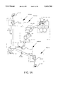
- FIG. 5 is a block schematic which illustrates a traffic situation in a telephone network where a mobile calling subscriber calls a mobile subscriber which belongs to the same local switchboard and where the called subscriber has asked for calls to be transferred to a fixed end-subscriber.
- FIGS. 6a-d illustrate a number of traffic situations in which the invention can be applied.
- a PDC-type mobile telephone network includes a central mobile telephone switching centre, a so-called main switch, which is connected to several local telephone switching centres, so-called local switches.
- Each local switch is connected to a number of base stations each supervising a geographical area, called a cell.
- Each of the local switches includes a local database referred to as a visitor location register.
- the visitor register contains all mobile units which are located at that particular time in one of the cells handled by the local switch.
- the mobile telephone network also includes a first central database, a so-called home location register, which is connected to both the main switch and to all visitor registers within the network. The mobile units which subscribe to the mobile telephone network operator are registered in the home register.
- the network also includes a second central database, a so-called main visitor location register which is also connected to all visitor registers within the network. Those mobile units which are temporarily located in the network but which belong to another mobile telephone network, i.e. which subscribe to another mobile telephone network operator, are registered in the main visitor register.
- the primary purpose of the main visitor register is to cut down signalling between the visitor register of the local network and the home register of another network.
- the total geographical area covered by the mobile telephone system is also divided into so-called message areas, normally rectangular areas. The position of the message areas within the total geographical area covered by the public switched network is given by a position coordinate which indicates the centre point of the message area.
- the area covered by a message area can vary.
- FIG. 1a illustrates only those local switches, visitor registers, message areas and base stations that are necessary in order to obtain an understanding of the invention. Multiples of these units have been excluded from the Figure, for the sake of clarification.
- a mobile unit B0 the so-called subscriber B0, belongs to a first mobile telephone network PLMN01, i.e. the subscriber B0 subscribes to the mobile telephone network PLMN01 and is therewith permanently registered in a home location register HLR0.
- the home register HLR0 is constantly updated with regard to the visitor register in which the called subscriber is at that moment registered within the local network, or in which mobile telephone network the subscriber is located when the subscriber is located in a network other than its local network.
- the called subscriber B0 is located in a second mobile telephone network PLMN02, more precisely within a cell which is controlled by a local switch MSC-B0.
- the called subscriber B0 is simultaneously registered temporarily in a first visitor register GLR-B0 and in a main visitor register GLR02 and is stationarily registered in the local home register HLR0.
- the main visitor register GLR02 is always kept updated in relation to the visitor register GLR-B0 in which the visiting mobile unit B0 is registered at that moment in time.
- the cell is located within the area covered by a message area, and the position coordinate CO-B0 of this message area, i.e. its centrepoint, is stored in the first visitor register GLR-B0.
- FIG. 1a also shows those parts of a public switched telephone network PSTN0 necessary to the illustrated embodiment of the invention.
- the public telephone network PSTN0 has been symbolized in the Figure by two mutually separated punctiform rectangles.
- a calling subscriber A0 and an end-subscriber C0 are fixedly connected to a respective public switching centre, the so-called first and second standard switches of exchanges EA0, EC0 in the public switched telephone network.
- the geographical position of the first public exchange EA0 is given by a position coordinate CO-A0 which is stored in the public switching centre.
- the geographical position of the second public standard exchange or switching centre EC0 is given by a position coordinate CO-C0 stored in the public switching centre.
- the public switches or exchanges EA0, EC0 are connected to the main switch GMSC01 in the first mobile telephone network PLMN01. Signalling between the public network PSTN0 and the first mobile telephone network PLMN01 is effected over its connection.
- the Figure shows only the signalling that takes place in the three networks PSTN0, PLMN01 and PLMN02, whereas signalling to and from the subscribers involved has been excluded from the Figure. Furthermore, neither the text nor the Figure include details of that part of the signalling procedure which is considered to form part of the known prior art.
- the mobile telephone systems PLMN01, PLMN02 operate in accordance with PDC specifications, although the method described below may also be applied in similar systems.
- the exemplifying embodiment described in detail below shows the call billing procedure adopted when the calling subscriber A0 calls the called subscriber B0 after the called subscriber B0 has asked for calls to be transferred to the end-subscriber C0.
- billing a call after a call transfer has been made in a mobile telephone system, it is important to be able to localize the geographical positions of the subscribers involved and to bring these positions together for comparison therebetween and for calculation of the distance involved.
- the inventive method which will now be presented is able to perform this essential function and icludes the following steps:
- the calling subscriber A0 calls the called subscriber B0.
- a first address message 01 which includes the call number of the called subscriber B0 is sent together with the position coordinate CO-A0 of the calling subscriber from the first country switch EA0 to the main switch GMSC01.
- the position coordinate CO-A0 of the calling subscriber is stored in the main switch GMSC01.
- a routing query 02 requesting the location of the called subscriber B0 i.e. asking for the local switch that handles the called subscriber B0, is sent from the main switch GMSC01 to the home register HLR0.
- the home register is aware of which mobile telephone network PLMN02 the called subscriber is located when this network is not the local network PLMN01.
- the home location register HLR0 ascertains that the called subscriber B0 has asked for calls to be transferred to the end-subscriber C0 and that the called subscriber is temporarily located in a second mobile telephone network PLMN02 which is handled by an operator other than the local operator, wherein the inventive method further includes the following steps:
- a coordinate query 03 asking for the position coordinate CO-B0 of the called subscriber B0 to be sent from the home register HLR0 to a main visitor register GLR02 in the second mobile telephone network PLMN02.
- the main visitor register GLR02 is cognizant of the visitor register GLR-B0 in the second network PLMN02 in which the called subscriber B0 is registered at that moment in time.
- a coordinate response 04 containing the position coordinate CO-B0 of the called subscriber B0 is sent from the main visitor register GLR02 to the home register HLR0.
- the position coordinate CO-B0 of the called subscriber B0 is stored in the main switch GMSC01.
- the distance between the position coordinate CO-A0 of the calling subscriber and the position coordinate CO-B0 of the called subscriber is assessed in the main switch GMSC01, wherein a preliminary decision is taken to connect the call. This preliminary decision will be explained in more detail below.
- Preparation is made to connect the call between the calling subscriber A0 and the end-subscriber C0.
- An address message 08 containing the call number of the end-subscriber CO is sent together with the position coordinate CO-B0 of the called subscriber B0 from the main switch GMSC01 to the second public exchange or switch EC0.
- the position coordinate CO-B0 of the called subscriber B0 is stored in the second public exchange EC0.
- the distance between the position coordinate CO-B0 of the called subscriber and the position coordinate CO-C0 of the end-subscriber is assessed in the second public exchange or switch EC0, wherein a final decision is taken to connect the call. This final decision will be explained in more detail below.
- the end-subscriber CO answers the call from the calling subscriber A0, by lifting his telephone receiver, wherewith the call is considered to have been connected.
- the cost i.e. a so-called primary call cost, covering the call between the calling subscriber A0 and the called subscriber BO is calculated in the main switch GMSC01, wherein the calling subscriber A0 is billed for the call.
- the cost covering the call between the called subscriber B0 and the end-subscriber C0, a so-called secondary call cost, is assessed in the second public exchange EC0 and the called subscriber B0 is billed for the cost.
- the calling subscriber A0 has specified a distance condition relating to the maximum distance which can be permitted between the calling subscriber A0 and the called subscriber B0 for the call to be connected.
- the preliminary decision as to whether or not the call shall be connected is made after assessing the distance between the two subscribers.
- the called subscriber B0 has specified a distance condition relating to the maximum distance which can be between the called subscriber B0 and the end-subscriber C0 for a call to be connected.
- the final decision as to whether or not a call shall be connected which is made only after the preliminary decision has been reached, is made after assessing the distance between the called subscriber B0 and the end-subscriber C0.
- the call is not connected until both the preliminary and the final decision have been taken to connect the call.
- the aforedescribed signalling procedure will be seen as an example of how signalling is effected when practicing the inventive method.
- the order in which the aforesaid method steps are carried out can vary. For instance, the distance between the calling subscriber A0 and the called subscriber B0 can be assessed and the cost of the call calculated at different stages than in the procedure than those stated above.
- a main visitor register GLR02 to obtain knowledge relating to the position coordinate of the message area in which the subscriber is located, in addition to having knowledge of the visitor register in which a visiting mobile subscriber is registered, wherein it is only necessary to signal between the home register and the main visitor register.
- FIG. 1b is a flow sheet which illustrates the aforedescribed method.
- the flow sheet and the following simplified description of the method are intended to be read together with FIG. 1a and the descriptive text associated with this Figure.
- the flow sheet illustrates the steps that are most essential to the concept on which the invention is based.
- the abbreviations included in the text in the Figure are considered to have been clearly explained in the aforegoing.
- the method is carried out in accordance with the following description and in accordance with FIG. 1b:
- the calling subscriber A0 calls the called subscriber B0, in accordance with block 001.
- An address message to the called subscriber B0 is sent from the first public exchange or switch EA0 to the main switch GMSCO1 together with the position coordinate CO-A0 of the calling subscriber A0.
- the position coordinate CO-A0 of the calling subscriber is stored in the main switching centre GMSCO1, in accordance with block 002.
- the home register HLR0 ascertains that the called subscriber B0 has requested call transfer to the end-subscriber C0 and that the called subscriber is located in another network PLMN02, in accordance with block 004.
- An enquiry with a request for the position coordinate CO-B0 of the called subscriber B0 is sent from the home register HLR0 to the main visitor register GLR02, in accordance with block 005.
- the request for the position coordinate CO-B0 of the called subscriber B0 is forwarded from the main visitor register GLR02 to the visitor register GLR-B0 of the called subscriber, in accordance with block 006.
- the position coordinate CO-B0 of the called subscriber B0 is sent from the visitor register GLR-B0 of the subscriber B0 to the main visitor register GLR02, in accordance with block 007.
- the position coordinate CO-B0 of the called subscriber B0 is sent from the main visitor register GLR02 to the home register HLR0, in accordance with block 008.
- the position coordinate CO-B0 of the called subscriber B0 is then stored in the main switch GMSCO1.
- the distance between the position coordinate CO-A0 of the calling subscriber and the position coordinate of the called subscriber is assessed in the main switch GMSC01, in accordance with block 010.
- a call connection between the calling subscriber A0 and the end-subscriber C0 is prepared, wherein the position coordinate CO-B0 of the called subscriber B0 is sent from the main switch GMSC01 to the second country switch EC0.
- the position coordinate CO-B0 of the called subscriber is stored in the second country switch EC0, in accordance with block 011.
- the distance between the position coordinate CO-B0 of the called subscriber B0 and the position coordinates CO-C0 of the end-subscriber C0 is assessed in the public exchange or switch EC0, in accordance with block 012.
- the end-subscriber C0 answers the call from the calling subscriber A0, by lifting his telephone receiver, in accordance with block 013.
- the cost of the call between the calling subscriber A0 and the called subscriber B0 is calculated, wherein the calling subscriber A0 is billed the cost, in accordance with block 014.
- the cost of the call between the called subscriber B0 and the end-subscriber CO is calculated and the called subscriber B0 is billed for the cost of this part of the call, in accordance with block 015.
- the aforedescribed method is only an example of one configuration of the ordered sequence in which the various method steps can be carried out. For instance, it is feasible to calculate the cost of the call in a later stage.
- the aforementioned coordinate query 03, 03' contained in the messages and the coordinate response 04', 04 will now be described in brief.
- the home register HLR0 and the main visitor register GLR02 are both able to communicate with earlier unknown interfaces.
- the protocol has a structure similar to the protocol used in a GSM mobile telephone network, namely "GSM 09.02MAP", i.e. the protocol described in GSM recommendation 09.02. Consequently, the protocol can be structured by using a CCITT No. 7 based protocol MAP, SCCP and TCAP from the protocol stack of CCITT No. 7.
- CCITT No. 7 is well known to the person skilled in this art.
- the MAP operation between the home register HLR0 and the main visitor register GLR02 and between the main visitor register GLR02 and the visitor register GLR-B0, i.e. the messages coordinate query 03, 03' and coordinate response 04', 04 can be described according to ASN.1 (CCITT recommendation X.208) as shown below:
- the message coordinate query 03 (GetMSC/GLRData) is sent from the home register HLR0 to the main visitor register GLR02, while stating the identity number (IMSI) of the called mobile subscriber B0.
- the message coordinate query 03' (GetMSC/GLRData) is sent from the main visitor register GLR02 to the visitor register GLR-B0 together with the identity number (IMSI) of the called mobile subscriber B0.
- IMSI identity number
- a coordinate response 04' including the position coordinate CO-B0 (MessageArea) is sent from the visitor register GLR-B0 to the main visitor register GLR02.
- a coordinate response 04 including the position coordinate CO-B0 (MessageArea) is sent from the main visitor register GLR02 to the home register HLR0.
- FIG. 2a illustrates solely the local switches, visitor registers, message areas and base stations that are necessary to understand the invention. Multiples of these units have been excluded from the Figure as in the earlier case, for the sake of simplicity.
- a mobile unit B1, the called subscriber B1 belongs to a mobile telephone network PLMN1 and is located within a cell controlled by a first local switching centre MSC-B1.
- the called subscriber B1 is thus registered temporarily in a first visitor register GLR-B1 and permanently registered in a home register HLR1.
- the home register HLR1 is constantly updated with regard to the visitor register GLR-B1 in which the mobile unit B1 is registered temporarily.
- the cell is located within the area covered by a message area, and the position coordinate CO-B1 of which message area, i.e. its centre point, is stored in the first visitor register GLR-B1.
- the end-subscriber C1 is, at the same time, registered temporarily in a second visitor register GLR-C1 and is permanently registered in the home register HLR1.
- the cell is located within the coverage area of a message area and the position coordinate CO-C1 of the message area is stored in the second visitor location register GLR-C1.
- All permanent connections between the earlier enumerated signalling nodes i.e. subscribers, switches, registers and base stations
- Signalling which is described in detail below, takes place over the permanent connections, although this signalling has been shown with thin full lines on one side of the permanent connections, for the sake of clarity.
- the arrows shown on the signalling lines indicate the directions in which signalling takes place.
- the called subscriber B1 and the end-subscriber C1 communicate with respective base stations BS via a radio link.
- the radio link has been shown in the Figure by a zig-zag marking between base stations and mobile subscribers.
- the signalling necessary to the invention and illustrated in the Figure does not claim to be the total signalling that is carried out when connecting a call. Only the signalling in the two networks PSTN1 and PLMN1 is shown in the Figure, while signalling to and from the subscribers involved has been excluded. Neither has that signalling which is considered to belong to the state of the art been described or shown.
- the mobile telephone system PLMN1 functions according to PDC-specifications, although the method now described can also be applied in systems of similar types.
- the following exemplifying embodiment illustrates the procedure followed when billing a call when the calling subscriber A1 calls the called subscriber B1 after the called subscriber B1 has asked for calls to be transferred to the end-subscriber C1.
- call billing after a call transfer service has been requested in a mobile telephone system, it is essential to be able to localize the geographical positions of the subscribers involved and to bring these positions together for comparison with one another and for calculation of the distance therebetween.
- the following inventive method is able to carry out this important function and includes the following steps:
- a first address message 11 which includes the call number of the called subscriber B1 is sent from the public exchange E1 to the main switch GMSC, together with the position coordinate CO-A1 of the calling subscriber.
- the position coordinate CO-A1 of the calling subscriber is stored in the main switch GMSC.
- the home location register HLR1 establishes that the called subscriber B1 has asked for calls to be transferred to the end-subscriber C1, wherein the inventive method includes the following further steps:
- a coordinate response 14 including the position coordinate CO-B1 of the called subscriber B1 is sent from the first visitor register GLR-B1 to the home register HLR1.
- the following part of the method belongs to conventional signalling procedure within PDC mobile telephony and is not therefore explained in detail.
- the purpose of this procedure is to make clear to the main switch GMSC the location of the end-subscriber C1 at that moment in time, so that messages from the main switch can be directed or routed to this destination. This is achieved by virtue of the main switch GMSC communicating with the home location register HLR1 and therewith obtaining routing information relating to the end-subscriber C1.
- the inventive method thereafter includes the following further steps:
- the position coordinate CO-B1 of the called subscriber B1 is stored in the second local switch MSC-C1.
- the position coordinate CO-C1 of the end-subscriber C1 is taken from the second visitor register GLR-Cl to the second local switch MSC-C1.
- the position coordinate CO-C1 of the end-subscriber C1 is stored in the second local switch MSC-C1.
- the distance between the position coordinate CO-A1 of the calling subscriber A1 and the position coordinate CO-B1 of the called subscriber B1 is assessed in the main switching centre GMSC.
- the distance between the position coordinate CO-B1 of the called subscriber B1 and the position coordinate CO-C1 of the end-subscriber C1 is assessed in the second local switch MSC-C1.
- the end-subscriber C1 answers the call from the calling subscriber A1, by lifting his telephone receiver, wherewith the call is considered to be connected.
- the cost of the call between the called subscriber B1 and the end-subscriber C1 is calculated in the second local switching centre MSC-C1 and the called subscriber B1 is billed for this part of the call.
- the aforedescribed signalling procedure will be seen as an example of how signalling may take place when practicing the inventive method. It will be understood that the order in which the method steps are carried out may vary. For instance, the distance between the calling subscriber A1 and the called subscriber B1 and also calculation of the call cost can be done in an earlier stage.
- FIG. 2b is a flowsheet illustrating the above-described method.
- the flowsheet and the following simplified description of the method are intended to be read together with FIG. 2a and with the descriptive text relating to this Figure.
- the flowsheet illustrates the steps that are most essential to the concept of the invention.
- the abbreviations used in the text shown in the Figure have been explained in the aforegoing.
- the method is carried out in accordance with the following description and also in accordance with FIG. 2b:
- the calling subscriber A1 calls the called subscriber B1, in accordance with block 101.
- An address message to the called subscriber B1 is sent from the public exchange or switch E1 to the main switch GMSC, together with the position coordinate CO-A1 of the calling subscriber A1.
- the position coordinate CO-A1 of the calling subscriber is stored in the main switch GMSC, in accordance with block 102.
- the home register HLR1 establishes that the called subscriber B1 has asked for calls to be transferred to the end-subscriber C1, in accordance with block 104.
- a query with a request for the position coordinate CO-B1 of the called subscriber B1 is sent from the home register HLR1 to the first visitor register GLR-B1, in accordance with block 105.
- the position coordinate CO-B1 of the called subscriber B1 is sent from the first visitor register GLR-B1 to the home register HLR1, in accordance with block 106.
- the position coordinate CO-B1 of the called subscriber is then stored in the main switching centre GMSC.
- the information necessary to localize the end-subscriber C1 is taken from the home register HLR1 to the main switch GMSC, in accordance with block 108.
- connection of the call between the calling subscriber A1 and the end-subscriber C1 can now be prepared, wherein the position coordinate C0-B1 of the called subscriber B1 is sent from the main switch GMSC to the second local switch MSC-C1.
- the position coordinate CO-B1 of the called subscriber is stored in the second local switch MSC-C1, in accordance with block 109.
- the position coordinate CO-C1 of the end-subscriber C1 is taken from the second visitor register GLR-C1 to the second local switch MSC-C1, in accordance with block 110.
- the position coordinate CO-C1 of the end-subscriber is stored in the second local switch MSC-C1.
- the distance between the position coordinate CO-A1 of the calling subscriber A1 and the position coordinate of the called subscriber B1 is assessed in the main switch GMSC, in accordance with block 111.
- the distance between the position coordinate CO-B1 of the called subscriber B1 and the position coordinate CO-C1 of the end-subscriber C1 is assessed in the local switch MSC-C1, in accordance with block 112.
- the end-subscriber C1 answers the call from the calling subscriber A1, by lifting his telephone receiver, in accordance with block 113.
- the cost of the call between the calling subscriber A1 and the called subscriber B1 is calculated and the calling subscriber A1 is billed for the cost, in accordance with block 114.
- the cost of the call between the called subscriber B1 and the end-subscriber C1 is calculated and the called subscriber B1 is billed for this part of the call, in accordance with block 115.
- the aforesaid messages coordinate query 13 and coordinate response 14 have the same structure as the messages described with reference to the earlier embodiment.
- the aforedescribed sequence in which the position coordinate CO-B1 of the called subscriber B1 is transferred to the home location register HLR1 is as follows:
- a coordinate response 14 containing the position coordinate CO-B1 (MessageArea) is sent from the visitor location register GLR-B1 to the home location register HLR1.
- a called subscriber B2 and an end-subscriber C1 are located in a PDC-type mobile telephone network (Personal Digital Cellular) similar to the case in the earlier embodiment.
- all local switches MSC also include the earlier described function of the main switch GMSC, i.e. the function whereby a connection can be established between the mobile telephone network and an external telephone network through the medium of a selected local switching centre, and whereby signalling between an external telephone network and the local switching centre need not take place over the main switching centre illustrated in the earlier embodiment.
- the PDC network is clearly specified in the standard Internode Specification for Digital Mobile Communications Network, Ver. 3.2.
- FIG. 3a shows only those local switches, visitor registers, message areas and base stations that are necessary in obtaining an understanding of the invention.
- the called subscriber B2 and the end-subscriber C2 belong to a mobile telephone network PLMN2 and are handled by the same type of equipment as that described in the earlier embodiment, namely local switches MSC-B2, MSC-C2 and visitor registers GLR-B2, GLR-C2 and a home register HLR2.
- the local switches and the visitor registers are referred to as first and second local switches MSC-B2 and MSC-C2 and first and second visitor registers GLR-B2 and GLR-C2 respectively.
- FIG. 2a also shows those parts of a public switched telephone network PSTN2 necessary to the illustrated embodiment.
- a calling subscriber A2 is permanently connected to a standard public exchange E2 in the public telephone network.
- the signalling necessary to the invention shown in the Figure does not claim to be the full signalling procedure that is carried out when connecting a call.
- the Figure solely shows the signalling that is carried out in the two networks PSTN2 and PLMN2 while signalling to and from the subscribers involved has been excluded from the Figure. Neither the text nor the details shown in the Figure include signalling that is considered to belong to the state of the art.
- the embodiment described below is concerned with the procedure adopted in billing a call when the calling subscriber A2 calls the called subscriber B2 after the called subscriber B2 has asked for calls to be transferred to the end-subscriber C2.
- the inventive method described below is able to perform this important function and comprises the following steps:
- a first address message 21 which includes the called number of the called subscriber B2 is sent from the standard public exchange E2 to the first local switching centre MSC-B2, together with the position coordinate CO-A2 of the calling subscriber. It should be pointed out that the choice of just this local switching centre MSC-B2 is taken without knowing whether the called subscriber B2 is handled by just this switch or not.
- the position coordinate CO-A2 of the calling subscriber is stored in the first local switch MSC-B2.
- the home register is cognizant of the visitor register in which the called subscriber is registered at that moment in time.
- a coordinate query 23 with a request for the position coordinate CO-B2 of the called subscriber B2 is sent from the home register HLR2 to the first visitor register GLR-B2 in which the called subscriber B2 is registered at that time.
- a coordinate response 24 which includes the position coordinate CO-B2 of the called subscriber B2 is sent from the first visitor register GLR-B2 to the home register HLR2.
- a routing response 25 to the aforesaid routing query 22 which includes the subscriber number of the end-subscriber is sent from the home register HLR2 to the first local switch MSC-B2, together with the position coordinate CO-B2 of the second subscriber.
- the position coordinate CO-B2 of the called subscriber B2 is stored in the first local switch MSC-B2.
- the distance between the position coordinate CO-A2 of the calling subscriber and the position coordinate CO-B2 of the called subscriber is assessed in the first local switch MSC-B2.
- the next part of the method belongs to conventional signalling procedure within PDC mobile telephony and will not therefore be explained in detail.
- the purpose of the method is to make clear to the first local switch MSC-B2 the whereabouts of the end-subscriber C2 at that moment in time, so that messages from the local switch can be routed to this destination. This is achieved by virtue of the first local switch MSC-C2 communicating with the home register HLR2 and therewith obtaining routing information relating to the end-subscriber C2.
- the inventive method then includes the following further steps:
- the position coordinate CO-C2 of the end-subscriber C2 is taken from the second visitor register GLR-C2 and transferred to the second local switch MSC-C2.
- the distance between the position coordinate CO-B2 of the called subscriber and the position coordinate CO-C2 of the end-subscriber is assessed in the second local switch MSC-C2.
- the cost of the call between the calling subscriber A2 and the called subscriber B2 is calculated in the first local switch MSC-B2, and the calling subscriber A2 is billed for this part of the call.
- the cost of the call between the called subscriber B2 and the end-subscriber C2 is calculated in the second local switch MSC-C2 and the called subscriber B2 is billed for this part of the call.
- the calling subscriber A2 calls the called subscriber B2, in accordance with block 201.
- An address message to the called subscriber B2 is sent from the standard exchange E2 to the first local switch MSC-B2, together with the position coordinate CO-A2 of the calling subscriber A2.
- the position coordinate CO-A1 of the calling subscriber is stored in the first local switch MSC-B2, in accordance with block 202.
- a routing query requesting a route to the called subscriber B2 is sent in accordance with known technology from the first local switch MSC-B2 to the home register HLR2, in accordance with block 203.
- the home register HLR2 establishes that the called subscriber B2 has asked for calls to be transferred to the end-subscriber C2, in accordance with block 204.
- a query asking for the position coordinate CO-B2 of the called subscriber B2 is sent from the home register HLR2 to the first visitor register GLR-B2, in accordance with block 205.
- the position coordinate CO-B2 of the called subscriber B2 is sent from the first visitor register GLR-B2 to the home register HLR2, in accordance with block 206.
- a routing response in answer to the earlier routing query and containing the call number to the end-subscriber C2 is sent from the home register HLR2 to the first local switch MSC-B2 together with the position coordinate CO-B2 of the called subscriber, in accordance with block 207.
- the position coordinate CO-B2 of the called subscriber B2 is then stored in the first local switch MSC-B2.
- the distance between the position coordinate CO-A2 of the calling subscriber A2 and the position coordinate of the called subscriber B2 is then assessed in the first local switch MSC-B2, in accordance with block 208.
- a call connection between the calling subscriber A2 and the end-subscriber C2 is prepared, wherein the position coordinate CO-B2 of the called subscriber B is sent from the first switch MSC-B2 to the second local switch MSC-C2.
- the position coordinate CO-B2 of the called subscriber is stored in the second local switch MSC-C1, in accordance with block 210.
- the position coordinate C0-C2 of the end-subscriber C2 is taken from the second visitor register GLR-C2 and transferred to the second local switch MSC-C2, in accordance with block 211.
- the position coordinate C0-C2 of the end-subscriber is stored in the second local switch MSC-C2.
- the distance between the position coordinate CO-B2 of the called subscriber B2 and the position coordinate CO-C2 of the end-subscriber C2 is assessed in the local switch MSC-C2, in accordance with block 212.
- the end-subscriber C2 answers the call from the calling subscriber A2 by lifting his telephone receiver, in accordance with block 213.
- the cost of the call between the calling subscriber A2 and the called subscriber B2 is calculated and the calling subscriber A2 is debited for this part of the call, in accordance with block 214.
- the cost of the call between the called subscriber B2 and the end-subscriber C2 is calculated and the called subscriber B2 is debited for the cost of this part of the call, in accordance with block 215.
- the messages coordinate query 23 and coordinate response 24 have the same structure as the messages described above in earlier embodiments.
- FIG. 4a shows only those signalling nodes that are necessary to explain the invention.
- the calling subscriber A3 and the called subscriber B3 belong to a mobile telephone network PLMN3 and are handled by the same type of equipment as that described in regard of the earlier embodiments, namely local switches MSC-A3, MSC-B3 and visitor registers GLR-A3, GLR-B3 and a home register HLR3.
- the local switches and the visitor registers are referred to as first and second local switches MSC-A3 and MSC-B3 and as first and second visitor registers GLR-A3 and GLR-B3 respectively.
- FIG. 4a also illustrates those parts of a public switched telephone network PSTN3 necessary to the embodiment.
- An end-subscriber C3 is connected permanently to a standard public exchange E3 in the public telephone network.
- the geographical location of the standard exchange E3 is given by a position coordinate CO-C3 stored in the standard exchange.
- Drawing details such as line types for permanent connections and signalling markings have been illustrated in FIG. 4a in the same way as that described with reference to and shown in FIG. 1a.
- the signalling necessary to the invention and illustrated in the Figure does not claim to be the total signalling that is effected when connecting a call. Only signalling in the two networks PSTN3 and PLMN3 has been shown in the Figure, while signalling to and from the subscribers involved has been excluded. Neither the text nor the details in the Figure show the signalling that is considered to belong to the state of the art.
- the calling subscriber A3 calls the called subscriber B3.
- the position coordinate CO-A3 of the calling subscriber is taken from the first visitor register GLR-A3 and stored in the first local switch MSC-A3.
- a routing query 32 asking for the location of the called subscriber B3, i.e. asking for the identity of the local switch which handles the called subscriber B3, is sent from the first local switch MSC-A3 to the home register HLR3.
- the home register cognizant with the visitor register in which the called subscriber is registered at that moment.
- the home register HLR3 establishes that the called subscriber B3 has asked for calls to be transferred to the end-subscriber C3, wherein the inventive method includes the following further steps:
- a coordinate query 33 asking for the position coordinate CO-B3 of the called subscriber B3 is sent from the home register HLR3 to the second visitor register GLR-B3 in which the called subscriber B3 is registered.
- a coordinate response 34 including the position coordinate CO-B3 of the called subscriber B3 is sent to the home register HLR3 from the second visitor register GLR-B3.
- a routing response 37 in answer to the earlier-mentioned routing query 32 and including the call number to the end-subscriber C3 is sent to the first local switch MSC-A3 from the home register HLR3, together with the position coordinate CO-B3 of the called subscriber.
- the position coordinate CO-B3 of the called subscriber B3 is stored in the first local switch MSC-A3.
- the distance between the position coordinate CO-A3 of the calling subscriber A3 and the position coordinate CO-B3 of the called subscriber B3 is assessed in the first local switch MSC-A3.
- a called connection between the calling subscriber A3 and the end-subscriber C3 is prepared.
- An address message 38 including the call number of the end-subscriber C3 is sent to the standard public exchange E3 from the first local switch MSC-A3, together with the position coordinate CO-B3 of the called subscriber B3.
- the position coordinate CO-B3 of the called subscriber B3 is stored in the standard public exchange E3.
- the distance between the position coordinate CO-B3 of the called subscriber B3 and the position coordinate C0-C3 of the end-subscriber C3 is assessed in the standard public exchange E3.
- the end-subscriber C3 answers the call from the calling subscriber A3 by lifting his telephone receiver, wherewith the call is considered as connected.
- the cost of the call between the calling subscriber A3 and the called subscriber B3 is calculated in the first local switch MSC-A3 and the calling subscriber A3 is billed for the cost entailed thereby.
- the cost of the call between the called subscriber B3 and the end-subscriber C3 is calculated in the local switch MSC-C3 and the called subscriber B3 is billed for this part of the call.
- the calling subscriber A3 calls the called subscriber B3, in accordance with block 301.
- a routing query asking for the route to the called subscriber B3 is sent in accordance with known technology from the first local switching centre MSC-A3 to the home location register HLR3, in accordance with block 303.
- the home register HLR3 establishes that the called subscriber B3 has asked for calls to be transferred to the end-subscriber C3, in accordance with block 304.
- a query containing the request for the position coordinate CO-B3 of the called subscriber B3 is sent from the home register HLR3 to the second visitor location register GLR-B3, in accordance with block 305.
- the distance between the position coordinate CO-A3 of the calling subscriber and the position coordinate CO-B3 of the called subscriber is assessed in the first local switch MSC-A3, in accordance with block 308.
- the distance between the position coordinate CO-B3 of the called subscriber and the position coordinate CO-C3 of the end-subscriber is assessed in the standard public exchange E3, in accordance with block 310.
- the cost of the call between the calling subscriber A3 and the called subscriber B3 is calculated and the calling subscriber A3 is billed for the cost, in accordance with block 312.
- the cost of the call between the called subscriber B3 and the end-subscriber C3 is calculated and the called subscriber B3 is billed for the cost, in accordance with block 313.
- the messages coordinate query 33 and coordinate response 34 have the same structure as those messages described above with reference to the earlier embodiments.
- a calling subscriber A4 and a called subscriber B4 are located within one and the same local exchange included in a PDC-type mobile telephone network.
- FIG. 5 illustrates solely those signalling nodes that are necessary to the invention.
- the calling subscriber A4 and the called subscriber B4 belong to a mobile telephone network PLMN4.
- Each of the mobile subscribers is located within its respective cell, these cells being handled by one and the same local switching centre MSC-B4.
- the subscribers are handled with the same type of equipment as that described with reference to earlier embodiments, namely the local switching centre MSC-B4 and a visitor location register GLR-B4, and a home location register HLR4.
- the local switch and the visitor register are referred to in this embodiment as a first local switch MSC-B4 and a first visitor register GLR-B4 respectively.
- FIG. 5 also shows those parts of a public switched telephone network PSTN4.
- An end-subscriber C4 is permanently connected to a standard public exchange E4 in the public telephone network.
- the geographic position of the public exchange E4 is given by a position coordinate CO-C4 stored in the exchange.
- the calling subscriber A4 calls the called subscriber B4.
- the position coordinate CO-A4 of the calling subscriber is taken from the first visitor register GLR-B4 and stored in the first local switch MSC-B4.
- a routing query 42 asking to be informed of the location of the called subscriber B4, i.e. a query asking to be informed of the local switch that handles the called subscriber B4, is sent from the first local switch MSC-B4 to the home register HLR4.
- the home register is cognizant with the visitor register in which the called subscriber is registered at that moment in time.
- the home register HLR4 establishes that the called subscriber B4 has asked for calls to be transferred to the end-subscriber C4, wherein the inventive method includes the following further steps:
- a coordinate query 43 asking for the position coordinate CO-B4 of the called subscriber B4 is sent from the home register HLR4 to the first visitor register GLR-B4 in which the called subscriber B4 is registered at that moment in time.
- a coordinate response 44 containing the position coordinate CO-B4 of the called subscriber B4 is sent from the first visitor register GLR-B4 to the home register HLR4.
- a routing response 45 in answer to the aforesaid routing query 42 and containing routing information relating to the end-subscriber C4 is sent from the home register HLR4 to the first local switch MSC-B4, together with the position coordinate CO-B4 of the called subscriber.
- the position coordinate CO-B4 of the called subscriber B4 is stored in the first local switch MSC-B4.
- a call connection between the calling subscriber A4 and the end-subscriber C4 is prepared.
- An address message 48 containing the call number of the end-subscriber C4 is sent from the first local switch MSC-B4 to the standard exchange E4, together with the position coordinate CO-B4 of the called subscriber B4.
- the position coordinate CO-B4 of the called subscriber B4 is stored in the standard public exchange E4.
- the distance between the position coordinate CO-B4 of the called subscriber B4 and the position coordinate CO-C4 of the end-subscriber C4 is assessed in the public exchange E4.
- the end-subscriber C4 answers the call from the calling subscriber A4 by lifting his telephone receiver, whereupon the call is considered to have been connected.
- the cost of the call between the called subscriber B4 and the end-subscriber C4 is calculated in the public exchange E4 and the called subscriber B4 is billed for the cost.
- the illustrated and described exemplifying embodiments of the invention may be varied without departing from the scope of the invention.
- the local switching centres and the visitor location registers associated therewith have the form of one physical unit. It is conceivable, however, for the switching centre and the register to be two different units that are connected one with the other. This dissimilarity in configuration has no significance to the invention.
- the order in which the various method steps are carried out may vary, provided that the desired end result is obtained.
- the shape and size of the message areas may also vary. For instance, it is conceivable to represent each cell by one message area.
- FIGS. 6a-d illustrate with the aid of symbols other examples of traffic situations. The symbols are explained briefly below, followed by a brief analysis of each of the FIGS. 6a-d.
- a rectangle 501 corresponds to a mobile telephone network.
- An octagon 502 corresponds to a public switched telephone network.
- a triangle 503 corresponds to a main switching centre, the function of which has been earlier explained in connection with the above embodiments.
- a circle 504 corresponds to a local switching centre, this circle enclosing the subscribers that are handled by the local switching centre at that time.
- a second letter B corresponds to a called subscriber, which in this case is a mobile unit.
- FIG. 6a illustrates six different traffic situations with the aid of six part- Figures.
- a basic feature of the six traffic situations is that the called subscriber B and the calling subscriber A are permanently registered in different telephone networks 501, 502 and that a connection between the telephone networks is effected via a main switch 503.
- the first of the six part- Figures represents the second embodiment described above. As before mentioned, those instances in which the called subscriber is located in a mobile telephone network other than its local network have been indicated with broken lines.
- the third of these traffic situations is represented by the first embodiment described above.
- FIG. 6c illustrates examples of traffic situations with the aid of three part- Figures.
- a basic feature of these three traffic situations is that the calling subscriber A and the called subscriber B are located in one and the same mobile telephone network 501 but are handled by different local switching centres 504.
- the third of the three part- Figures is represented by the fourth embodiment described above.
- FIG. 6d illustrates examples of a further three traffic situations, with the aid of three part- Figures.
- a basic feature of the six traffic situations is that the calling subscriber A and the called subscriber B are located in one and the same mobile telephone network 501 and are handled by the same local switching centres 504.
- the third of the three part- Figures is represented by the fifth embodiment described above.
- the invention also relates to a telephone system which also includes mobile telephone systems and in which a mobile subscriber may request a call transfer service to an end-subscriber.
- the invention provides the advantage of enabling the costs of a call between a calling and a called subscriber to be shared fairly, in a ready fashion.
- the invention also enables the system to decide readily whether or not a call shall be connected in those cases when a subscriber has requested restrictions with regard to the connection of long distance calls.
Landscapes
- Engineering & Computer Science (AREA)
- Signal Processing (AREA)
- Computer Networks & Wireless Communication (AREA)
- Business, Economics & Management (AREA)
- Accounting & Taxation (AREA)
- Mobile Radio Communication Systems (AREA)
- Telephonic Communication Services (AREA)
- Meter Arrangements (AREA)
Applications Claiming Priority (2)
| Application Number | Priority Date | Filing Date | Title |
|---|---|---|---|
| SE9303491 | 1993-10-22 | ||
| SE9303491A SE502111C2 (sv) | 1993-10-22 | 1993-10-22 | Förfarande för inhämtning av anropande och anropad abonnents lägesangivelser för debiteringsändamål, i ett telesystem där den anropade abonnenten begärt samtalsförflyttning |
Publications (1)
| Publication Number | Publication Date |
|---|---|
| US5621783A true US5621783A (en) | 1997-04-15 |
Family
ID=20391515
Family Applications (1)
| Application Number | Title | Priority Date | Filing Date |
|---|---|---|---|
| US08/326,947 Expired - Fee Related US5621783A (en) | 1993-10-22 | 1994-10-21 | Method and an arrangement relating to telecommunications systems |
Country Status (7)
| Country | Link |
|---|---|
| US (1) | US5621783A (zh) |
| JP (1) | JPH08505276A (zh) |
| CN (1) | CN1116034A (zh) |
| GB (1) | GB2288303B (zh) |
| SE (1) | SE502111C2 (zh) |
| SG (1) | SG43754A1 (zh) |
| WO (1) | WO1995011578A1 (zh) |
Cited By (20)
| Publication number | Priority date | Publication date | Assignee | Title |
|---|---|---|---|---|
| US5819178A (en) * | 1996-01-05 | 1998-10-06 | Northern Telecom Limited | Methods and apparatus for accessing subscriber information in interconnected wireless telecommunications networks |
| US5839076A (en) * | 1995-03-13 | 1998-11-17 | Siemens Aktiengesellschaft | Method for the transmission of subscriber data between network nodes in at least one communications network supporting the structure of an intelligent network |
| US5878348A (en) * | 1996-05-30 | 1999-03-02 | Telefonaktiebolaget Lm Ericsson (Publ) | System and method for implementing multiple home location registers for a single mobile station in a cellular telecommunications network |
| US5890063A (en) * | 1996-06-03 | 1999-03-30 | Ericsson Inc. | Downloading of routing numbers to donor switches within a telecommunications network |
| US5890065A (en) * | 1995-12-21 | 1999-03-30 | Daewoo Telecom, Ltd. | Routing information generation method for use in a mobile communications system |
| US5978678A (en) * | 1996-06-07 | 1999-11-02 | Telefonaktiebolaget L M Ericsson (Publ) | Cellular telephone network routing method and apparatus for internationally roaming mobile stations |
| WO1999065260A1 (en) * | 1998-06-10 | 1999-12-16 | Motorola Inc. | Method for determining when a communication unit is located within a preferred zone |
| US6081731A (en) * | 1996-12-18 | 2000-06-27 | Ericsson Inc. | Selective carrier denial for mobile subscribers |
| US6134447A (en) * | 1998-05-29 | 2000-10-17 | Ericsson Inc. | System and method for monitoring and barring location applications |
| US6151498A (en) * | 1998-03-09 | 2000-11-21 | Ericsson Inc. | System and method for routing positioning requests based on mobile switching center address |
| US6212377B1 (en) * | 1996-11-27 | 2001-04-03 | Ericsson Telefon Ab L M | System and method of providing group wireless extension phone service in a radio telecommunications network |
| US6233457B1 (en) * | 1996-11-18 | 2001-05-15 | Siemens Aktiengesellschaft | Method and mobile communication system for routing of call connections |
| US6363151B1 (en) * | 1996-07-31 | 2002-03-26 | Siemens Aktiengesellschaft | Method and system for subscriber authentification and/or encryption of items of information |
| US6400947B1 (en) * | 1998-03-05 | 2002-06-04 | Lucent Technologies Inc | Caller line identification for GSM and wireless communications systems |
| US6466788B1 (en) * | 1998-12-21 | 2002-10-15 | Telefonaktiebolaget Lm Ericsson (Publ) | Methods and apparatus for transferring position data between terminals in wireless communications systems |
| US6636504B1 (en) * | 1999-03-18 | 2003-10-21 | Verizon Services Corp. | Reverse billing of internet telephone calls |
| US6741849B1 (en) * | 1997-12-15 | 2004-05-25 | Nokia Corporation | Handling of forwarded calls |
| US6834186B1 (en) * | 1996-12-20 | 2004-12-21 | Avaya Technology Corp. | Wireless handset feature transparency between switching nodes |
| US20130268612A1 (en) * | 2010-12-17 | 2013-10-10 | Telefonaktiebolaget Lm Ericsson (Publ) | Enabling a communication server to use msc-s related functions |
| US11349986B2 (en) | 2020-10-27 | 2022-05-31 | T-Mobile Usa, Inc. | Customization of call forwarding or voicemail greetings based on location of wireless device |
Families Citing this family (10)
| Publication number | Priority date | Publication date | Assignee | Title |
|---|---|---|---|---|
| US5905954A (en) * | 1997-01-14 | 1999-05-18 | Telefonaktiebolaget Lm Ericsson (Publ) | Method and system for transferring subscriber information in a radio telecommunications network |
| US6097397A (en) * | 1997-11-20 | 2000-08-01 | Real 3D, Inc. | Anisotropic texture mapping using silhouette/footprint analysis in a computer image generation system |
| US8792118B2 (en) | 2007-09-26 | 2014-07-29 | Ringcentral Inc. | User interfaces and methods to provision electronic facsimiles |
| US8600391B2 (en) | 2008-11-24 | 2013-12-03 | Ringcentral, Inc. | Call management for location-aware mobile devices |
| US8838082B2 (en) | 2008-11-26 | 2014-09-16 | Ringcentral, Inc. | Centralized status server for call management of location-aware mobile devices |
| US8275110B2 (en) | 2007-09-28 | 2012-09-25 | Ringcentral, Inc. | Active call filtering, screening and dispatching |
| US8670545B2 (en) | 2007-09-28 | 2014-03-11 | Ringcentral, Inc. | Inbound call identification and management |
| US8073441B1 (en) | 2010-08-24 | 2011-12-06 | Metropcs Wireless, Inc. | Location-based network selection method for a mobile device |
| CN102448040B (zh) * | 2010-10-14 | 2016-06-22 | 中兴通讯股份有限公司 | 一种WiMAX网络中执行呼叫转移时的计费方法和系统 |
| US9424509B2 (en) | 2011-03-09 | 2016-08-23 | T-Mobile Usa, Inc. | System for application personalization for a mobile device |
Citations (9)
| Publication number | Priority date | Publication date | Assignee | Title |
|---|---|---|---|---|
| US2909607A (en) * | 1954-03-27 | 1959-10-20 | Ericsson Telefon Ab L M | Automatic telephone system with automatic transfer |
| US4187398A (en) * | 1977-03-07 | 1980-02-05 | Siemens Aktiengesellschaft | Telephone and data network for mobile subscribers |
| US4723273A (en) * | 1985-09-25 | 1988-02-02 | American Telephone And Telegraph Company, At&T Bell Laboratories | Discretionary call forwarding |
| US4788719A (en) * | 1987-11-13 | 1988-11-29 | American Telephone And Telegraph Company | Telephone call charge allocation arrangement |
| EP0510411A2 (en) * | 1991-04-26 | 1992-10-28 | Siemens Rolm Communications Inc. (a Delaware corp.) | Method and apparatus for handling incoming telephone calls |
| WO1992022174A1 (en) * | 1991-06-06 | 1992-12-10 | Nokia Telecommunications Oy | Method for establishing an inbound call to the mobile telephone in a cellular mobile telephone network |
| EP0531048A2 (en) * | 1991-09-03 | 1993-03-10 | AT&T Corp. | A system for providing personalized telephone calling features |
| US5216703A (en) * | 1991-06-17 | 1993-06-01 | Pactel Corporation | Piggy-back number and routing isolation for cellular telephone switches |
| US5217703A (en) * | 1991-08-28 | 1993-06-08 | United Technologies Corporation | Method of manufacture of iron oxide particles |
-
1993
- 1993-10-22 SE SE9303491A patent/SE502111C2/xx not_active IP Right Cessation
-
1994
- 1994-10-20 CN CN94190818.6A patent/CN1116034A/zh active Pending
- 1994-10-20 SG SG1996000596A patent/SG43754A1/en unknown
- 1994-10-20 GB GB9510010A patent/GB2288303B/en not_active Expired - Fee Related
- 1994-10-20 WO PCT/SE1994/000991 patent/WO1995011578A1/en active Application Filing
- 1994-10-20 JP JP7511700A patent/JPH08505276A/ja not_active Ceased
- 1994-10-21 US US08/326,947 patent/US5621783A/en not_active Expired - Fee Related
Patent Citations (12)
| Publication number | Priority date | Publication date | Assignee | Title |
|---|---|---|---|---|
| US2909607A (en) * | 1954-03-27 | 1959-10-20 | Ericsson Telefon Ab L M | Automatic telephone system with automatic transfer |
| US4187398A (en) * | 1977-03-07 | 1980-02-05 | Siemens Aktiengesellschaft | Telephone and data network for mobile subscribers |
| SE422135B (sv) * | 1977-03-07 | 1982-02-15 | Siemens Ag | Telefon- och datanet for mobila abonnenter |
| US4723273A (en) * | 1985-09-25 | 1988-02-02 | American Telephone And Telegraph Company, At&T Bell Laboratories | Discretionary call forwarding |
| US4788719A (en) * | 1987-11-13 | 1988-11-29 | American Telephone And Telegraph Company | Telephone call charge allocation arrangement |
| EP0510411A2 (en) * | 1991-04-26 | 1992-10-28 | Siemens Rolm Communications Inc. (a Delaware corp.) | Method and apparatus for handling incoming telephone calls |
| WO1992022174A1 (en) * | 1991-06-06 | 1992-12-10 | Nokia Telecommunications Oy | Method for establishing an inbound call to the mobile telephone in a cellular mobile telephone network |
| US5400390A (en) * | 1991-06-06 | 1995-03-21 | Nokia Telecommunications Oy | Method for establishing an inbound call to the mobile telephone in a GSM cellular mobile telephone network |
| US5216703A (en) * | 1991-06-17 | 1993-06-01 | Pactel Corporation | Piggy-back number and routing isolation for cellular telephone switches |
| US5217703A (en) * | 1991-08-28 | 1993-06-08 | United Technologies Corporation | Method of manufacture of iron oxide particles |
| EP0531048A2 (en) * | 1991-09-03 | 1993-03-10 | AT&T Corp. | A system for providing personalized telephone calling features |
| US5222125A (en) * | 1991-09-03 | 1993-06-22 | At&T Bell Laboratories | System for providing personalized telephone calling features |
Non-Patent Citations (8)
| Title |
|---|
| CCITT Recommendation X.208, pp. 60 71 (1988). * |
| CCITT Recommendation X.208, pp. 60-71 (1988). |
| CME 20, BSC Operation and Maintenance, System Description, pp. 5 48 (1993). * |
| CME 20, BSC Operation and Maintenance, System Description, pp. 5-48 (1993). |
| GSM Recommendation 09.02, "GSM 09.02 MAP" (X.219), pp. 47-50, 229-235, 200-262, 477-478 (Nov. 1994). |
| GSM Recommendation 09.02, GSM 09.02 MAP (X.219), pp. 47 50, 229 235, 200 262, 477 478 (Nov. 1994). * |
| Internode Specification for Digital Mobile Communications Network, Ver. 3.2, pp. 1 18 (Jul. 9, 1992). * |
| Internode Specification for Digital Mobile Communications Network, Ver. 3.2, pp. 1-18 (Jul. 9, 1992). |
Cited By (22)
| Publication number | Priority date | Publication date | Assignee | Title |
|---|---|---|---|---|
| US5839076A (en) * | 1995-03-13 | 1998-11-17 | Siemens Aktiengesellschaft | Method for the transmission of subscriber data between network nodes in at least one communications network supporting the structure of an intelligent network |
| US5890065A (en) * | 1995-12-21 | 1999-03-30 | Daewoo Telecom, Ltd. | Routing information generation method for use in a mobile communications system |
| US5819178A (en) * | 1996-01-05 | 1998-10-06 | Northern Telecom Limited | Methods and apparatus for accessing subscriber information in interconnected wireless telecommunications networks |
| US5878348A (en) * | 1996-05-30 | 1999-03-02 | Telefonaktiebolaget Lm Ericsson (Publ) | System and method for implementing multiple home location registers for a single mobile station in a cellular telecommunications network |
| US5890063A (en) * | 1996-06-03 | 1999-03-30 | Ericsson Inc. | Downloading of routing numbers to donor switches within a telecommunications network |
| US5978678A (en) * | 1996-06-07 | 1999-11-02 | Telefonaktiebolaget L M Ericsson (Publ) | Cellular telephone network routing method and apparatus for internationally roaming mobile stations |
| US6363151B1 (en) * | 1996-07-31 | 2002-03-26 | Siemens Aktiengesellschaft | Method and system for subscriber authentification and/or encryption of items of information |
| US6233457B1 (en) * | 1996-11-18 | 2001-05-15 | Siemens Aktiengesellschaft | Method and mobile communication system for routing of call connections |
| US6212377B1 (en) * | 1996-11-27 | 2001-04-03 | Ericsson Telefon Ab L M | System and method of providing group wireless extension phone service in a radio telecommunications network |
| US6081731A (en) * | 1996-12-18 | 2000-06-27 | Ericsson Inc. | Selective carrier denial for mobile subscribers |
| US6834186B1 (en) * | 1996-12-20 | 2004-12-21 | Avaya Technology Corp. | Wireless handset feature transparency between switching nodes |
| US6741849B1 (en) * | 1997-12-15 | 2004-05-25 | Nokia Corporation | Handling of forwarded calls |
| US6400947B1 (en) * | 1998-03-05 | 2002-06-04 | Lucent Technologies Inc | Caller line identification for GSM and wireless communications systems |
| US6151498A (en) * | 1998-03-09 | 2000-11-21 | Ericsson Inc. | System and method for routing positioning requests based on mobile switching center address |
| US6134447A (en) * | 1998-05-29 | 2000-10-17 | Ericsson Inc. | System and method for monitoring and barring location applications |
| WO1999065260A1 (en) * | 1998-06-10 | 1999-12-16 | Motorola Inc. | Method for determining when a communication unit is located within a preferred zone |
| US6466788B1 (en) * | 1998-12-21 | 2002-10-15 | Telefonaktiebolaget Lm Ericsson (Publ) | Methods and apparatus for transferring position data between terminals in wireless communications systems |
| US6636504B1 (en) * | 1999-03-18 | 2003-10-21 | Verizon Services Corp. | Reverse billing of internet telephone calls |
| US20130268612A1 (en) * | 2010-12-17 | 2013-10-10 | Telefonaktiebolaget Lm Ericsson (Publ) | Enabling a communication server to use msc-s related functions |
| US9667798B2 (en) * | 2010-12-17 | 2017-05-30 | Telefonaktiebolaget L M Ericsson (Publ) | Enabling a communication server to use MSC-S related functions |
| US11349986B2 (en) | 2020-10-27 | 2022-05-31 | T-Mobile Usa, Inc. | Customization of call forwarding or voicemail greetings based on location of wireless device |
| US11689659B2 (en) | 2020-10-27 | 2023-06-27 | T-Mobile Usa, Inc. | Customization of call forwarding or voicemail greetings based on location of wireless device |
Also Published As
| Publication number | Publication date |
|---|---|
| GB2288303A (en) | 1995-10-11 |
| GB2288303B (en) | 1998-01-28 |
| SG43754A1 (en) | 1997-11-14 |
| SE9303491D0 (sv) | 1993-10-22 |
| SE9303491L (sv) | 1995-04-23 |
| JPH08505276A (ja) | 1996-06-04 |
| GB9510010D0 (en) | 1995-07-19 |
| SE502111C2 (sv) | 1995-08-21 |
| WO1995011578A1 (en) | 1995-04-27 |
| CN1116034A (zh) | 1996-01-31 |
Similar Documents
| Publication | Publication Date | Title |
|---|---|---|
| US5621783A (en) | Method and an arrangement relating to telecommunications systems | |
| US5406616A (en) | Method of completing a telephone call in a telephone system | |
| US5610974A (en) | Method and arrangement for handling a mobile telephone subscriber administered in different mobile telephone networks with a common call number | |
| AU745537B2 (en) | Selective carrier denial for mobile subscribers | |
| US6505050B1 (en) | Method and apparatus for suppressing route request messages for wireless gateway applications | |
| AU672293B2 (en) | A method of restructuring a call signal frame in a cellular mobile telephone system | |
| US5537457A (en) | Method for handling calls to a non-registered mobile subscriber in a mobile telephone system | |
| US6556831B1 (en) | Telecommunication system | |
| FI97510C (fi) | Menetelmä puhelun hinnan laskentaperusteiden parantamiseksi matkapuhelinverkossa | |
| WO1994018805A9 (en) | A method of completing a telephone call in a telephone system | |
| US8014780B2 (en) | Method for transmitting the identity of a calling subscriber to a called subscriber in a mobile communication system | |
| US6236853B1 (en) | Called mobile subscriber present status | |
| US7224975B2 (en) | Procedure and system for setting up a telecommunication connection | |
| JP4022793B2 (ja) | 時差補正時刻による通信付加サービスシステム | |
| WO2000033600A1 (en) | Optimized routing of mobile calls within a telecommunications network | |
| USRE37276E1 (en) | Method and arrangement for handling a mobile telephone subscriber administered in different mobile telephone networks with a common call number | |
| US6625453B1 (en) | Efficient wireless call delivery across regional and political boundaries | |
| US6782254B1 (en) | Handling of forward-to numbers across regional and political boundaries | |
| MXPA99005649A (en) | Selective carrier denial for mobile subscribers |
Legal Events
| Date | Code | Title | Description |
|---|---|---|---|
| AS | Assignment |
Owner name: TELEFONAKTIEBOLAGET LM ERICSSON, SWEDEN Free format text: ASSIGNMENT OF ASSIGNORS INTEREST;ASSIGNORS:LANTTO, SVEN JORGEN;STILLE, MATS OLA;GANDILS, MATS WERNER;AND OTHERS;REEL/FRAME:007292/0111 Effective date: 19940926 |
|
| FEPP | Fee payment procedure |
Free format text: PAYOR NUMBER ASSIGNED (ORIGINAL EVENT CODE: ASPN); ENTITY STATUS OF PATENT OWNER: LARGE ENTITY |
|
| FPAY | Fee payment |
Year of fee payment: 4 |
|
| REMI | Maintenance fee reminder mailed | ||
| LAPS | Lapse for failure to pay maintenance fees | ||
| STCH | Information on status: patent discontinuation |
Free format text: PATENT EXPIRED DUE TO NONPAYMENT OF MAINTENANCE FEES UNDER 37 CFR 1.362 |
|
| FP | Lapsed due to failure to pay maintenance fee |
Effective date: 20050415 |