US5595834A - Annular feed air breathing fuel cell stack - Google Patents
Annular feed air breathing fuel cell stack Download PDFInfo
- Publication number
- US5595834A US5595834A US08/587,430 US58743096A US5595834A US 5595834 A US5595834 A US 5595834A US 58743096 A US58743096 A US 58743096A US 5595834 A US5595834 A US 5595834A
- Authority
- US
- United States
- Prior art keywords
- fuel
- polymer electrolyte
- fuel cell
- annular region
- stack
- Prior art date
- Legal status (The legal status is an assumption and is not a legal conclusion. Google has not performed a legal analysis and makes no representation as to the accuracy of the status listed.)
- Expired - Lifetime
Links
- 239000000446 fuel Substances 0.000 title claims abstract description 154
- 230000029058 respiratory gaseous exchange Effects 0.000 title 1
- 210000004027 cell Anatomy 0.000 claims abstract description 115
- QVGXLLKOCUKJST-UHFFFAOYSA-N atomic oxygen Chemical compound [O] QVGXLLKOCUKJST-UHFFFAOYSA-N 0.000 claims abstract description 36
- 239000001301 oxygen Substances 0.000 claims abstract description 36
- 229910052760 oxygen Inorganic materials 0.000 claims abstract description 36
- 239000005518 polymer electrolyte Substances 0.000 claims abstract description 31
- 210000003850 cellular structure Anatomy 0.000 claims abstract description 21
- 239000012528 membrane Substances 0.000 claims abstract description 21
- 238000009826 distribution Methods 0.000 claims abstract description 17
- XLYOFNOQVPJJNP-UHFFFAOYSA-N water Substances O XLYOFNOQVPJJNP-UHFFFAOYSA-N 0.000 claims abstract description 16
- 239000000463 material Substances 0.000 claims abstract description 9
- 238000001816 cooling Methods 0.000 abstract description 8
- 210000004379 membrane Anatomy 0.000 description 9
- UFHFLCQGNIYNRP-UHFFFAOYSA-N Hydrogen Chemical compound [H][H] UFHFLCQGNIYNRP-UHFFFAOYSA-N 0.000 description 6
- 238000009792 diffusion process Methods 0.000 description 6
- 239000001257 hydrogen Substances 0.000 description 6
- 229910052739 hydrogen Inorganic materials 0.000 description 6
- BASFCYQUMIYNBI-UHFFFAOYSA-N platinum Chemical compound [Pt] BASFCYQUMIYNBI-UHFFFAOYSA-N 0.000 description 5
- 230000000694 effects Effects 0.000 description 4
- 239000003570 air Substances 0.000 description 3
- 238000013461 design Methods 0.000 description 3
- 230000036571 hydration Effects 0.000 description 3
- 238000006703 hydration reaction Methods 0.000 description 3
- 238000004519 manufacturing process Methods 0.000 description 3
- 238000012986 modification Methods 0.000 description 3
- 230000004048 modification Effects 0.000 description 3
- 238000003860 storage Methods 0.000 description 3
- 210000004128 D cell Anatomy 0.000 description 2
- NBIIXXVUZAFLBC-UHFFFAOYSA-N Phosphoric acid Chemical compound OP(O)(O)=O NBIIXXVUZAFLBC-UHFFFAOYSA-N 0.000 description 2
- 239000012080 ambient air Substances 0.000 description 2
- 238000006243 chemical reaction Methods 0.000 description 2
- 239000004020 conductor Substances 0.000 description 2
- 238000001035 drying Methods 0.000 description 2
- 238000011068 loading method Methods 0.000 description 2
- 229910052987 metal hydride Inorganic materials 0.000 description 2
- 150000004681 metal hydrides Chemical class 0.000 description 2
- 238000013021 overheating Methods 0.000 description 2
- 229910052697 platinum Inorganic materials 0.000 description 2
- 239000000376 reactant Substances 0.000 description 2
- 238000007789 sealing Methods 0.000 description 2
- OKTJSMMVPCPJKN-UHFFFAOYSA-N Carbon Chemical compound [C] OKTJSMMVPCPJKN-UHFFFAOYSA-N 0.000 description 1
- 229920000049 Carbon (fiber) Polymers 0.000 description 1
- BVKZGUZCCUSVTD-UHFFFAOYSA-L Carbonate Chemical compound [O-]C([O-])=O BVKZGUZCCUSVTD-UHFFFAOYSA-L 0.000 description 1
- 230000009471 action Effects 0.000 description 1
- 229910052782 aluminium Inorganic materials 0.000 description 1
- XAGFODPZIPBFFR-UHFFFAOYSA-N aluminium Chemical compound [Al] XAGFODPZIPBFFR-UHFFFAOYSA-N 0.000 description 1
- 229910000147 aluminium phosphate Inorganic materials 0.000 description 1
- 230000004888 barrier function Effects 0.000 description 1
- OJIJEKBXJYRIBZ-UHFFFAOYSA-N cadmium nickel Chemical compound [Ni].[Cd] OJIJEKBXJYRIBZ-UHFFFAOYSA-N 0.000 description 1
- 239000004917 carbon fiber Substances 0.000 description 1
- 239000003054 catalyst Substances 0.000 description 1
- 239000007795 chemical reaction product Substances 0.000 description 1
- 239000011248 coating agent Substances 0.000 description 1
- 238000000576 coating method Methods 0.000 description 1
- 238000004891 communication Methods 0.000 description 1
- 230000006835 compression Effects 0.000 description 1
- 238000007906 compression Methods 0.000 description 1
- 230000003247 decreasing effect Effects 0.000 description 1
- 239000003792 electrolyte Substances 0.000 description 1
- 238000005516 engineering process Methods 0.000 description 1
- 239000004744 fabric Substances 0.000 description 1
- 229910002804 graphite Inorganic materials 0.000 description 1
- 239000010439 graphite Substances 0.000 description 1
- 150000004678 hydrides Chemical class 0.000 description 1
- 230000004941 influx Effects 0.000 description 1
- 239000011810 insulating material Substances 0.000 description 1
- 230000007774 longterm Effects 0.000 description 1
- 238000007726 management method Methods 0.000 description 1
- 229910052751 metal Inorganic materials 0.000 description 1
- 239000002184 metal Substances 0.000 description 1
- VNWKTOKETHGBQD-UHFFFAOYSA-N methane Chemical compound C VNWKTOKETHGBQD-UHFFFAOYSA-N 0.000 description 1
- 239000002245 particle Substances 0.000 description 1
- 230000010287 polarization Effects 0.000 description 1
- 239000011148 porous material Substances 0.000 description 1
- 238000010248 power generation Methods 0.000 description 1
- 239000000565 sealant Substances 0.000 description 1
- 239000007787 solid Substances 0.000 description 1
- 229910001220 stainless steel Inorganic materials 0.000 description 1
- 239000010935 stainless steel Substances 0.000 description 1
- 239000010409 thin film Substances 0.000 description 1
Images


Classifications
-
- H—ELECTRICITY
- H01—ELECTRIC ELEMENTS
- H01M—PROCESSES OR MEANS, e.g. BATTERIES, FOR THE DIRECT CONVERSION OF CHEMICAL ENERGY INTO ELECTRICAL ENERGY
- H01M8/00—Fuel cells; Manufacture thereof
- H01M8/04—Auxiliary arrangements, e.g. for control of pressure or for circulation of fluids
- H01M8/04291—Arrangements for managing water in solid electrolyte fuel cell systems
-
- H—ELECTRICITY
- H01—ELECTRIC ELEMENTS
- H01M—PROCESSES OR MEANS, e.g. BATTERIES, FOR THE DIRECT CONVERSION OF CHEMICAL ENERGY INTO ELECTRICAL ENERGY
- H01M8/00—Fuel cells; Manufacture thereof
- H01M8/10—Fuel cells with solid electrolytes
- H01M8/1007—Fuel cells with solid electrolytes with both reactants being gaseous or vaporised
-
- H—ELECTRICITY
- H01—ELECTRIC ELEMENTS
- H01M—PROCESSES OR MEANS, e.g. BATTERIES, FOR THE DIRECT CONVERSION OF CHEMICAL ENERGY INTO ELECTRICAL ENERGY
- H01M8/00—Fuel cells; Manufacture thereof
- H01M8/24—Grouping of fuel cells, e.g. stacking of fuel cells
- H01M8/241—Grouping of fuel cells, e.g. stacking of fuel cells with solid or matrix-supported electrolytes
-
- H—ELECTRICITY
- H01—ELECTRIC ELEMENTS
- H01M—PROCESSES OR MEANS, e.g. BATTERIES, FOR THE DIRECT CONVERSION OF CHEMICAL ENERGY INTO ELECTRICAL ENERGY
- H01M8/00—Fuel cells; Manufacture thereof
- H01M8/24—Grouping of fuel cells, e.g. stacking of fuel cells
- H01M8/2465—Details of groupings of fuel cells
- H01M8/2483—Details of groupings of fuel cells characterised by internal manifolds
-
- H—ELECTRICITY
- H01—ELECTRIC ELEMENTS
- H01M—PROCESSES OR MEANS, e.g. BATTERIES, FOR THE DIRECT CONVERSION OF CHEMICAL ENERGY INTO ELECTRICAL ENERGY
- H01M2300/00—Electrolytes
- H01M2300/0017—Non-aqueous electrolytes
- H01M2300/0065—Solid electrolytes
- H01M2300/0082—Organic polymers
-
- H—ELECTRICITY
- H01—ELECTRIC ELEMENTS
- H01M—PROCESSES OR MEANS, e.g. BATTERIES, FOR THE DIRECT CONVERSION OF CHEMICAL ENERGY INTO ELECTRICAL ENERGY
- H01M8/00—Fuel cells; Manufacture thereof
- H01M8/04—Auxiliary arrangements, e.g. for control of pressure or for circulation of fluids
- H01M8/04007—Auxiliary arrangements, e.g. for control of pressure or for circulation of fluids related to heat exchange
-
- H—ELECTRICITY
- H01—ELECTRIC ELEMENTS
- H01M—PROCESSES OR MEANS, e.g. BATTERIES, FOR THE DIRECT CONVERSION OF CHEMICAL ENERGY INTO ELECTRICAL ENERGY
- H01M8/00—Fuel cells; Manufacture thereof
- H01M8/04—Auxiliary arrangements, e.g. for control of pressure or for circulation of fluids
- H01M8/04082—Arrangements for control of reactant parameters, e.g. pressure or concentration
- H01M8/04089—Arrangements for control of reactant parameters, e.g. pressure or concentration of gaseous reactants
- H01M8/04119—Arrangements for control of reactant parameters, e.g. pressure or concentration of gaseous reactants with simultaneous supply or evacuation of electrolyte; Humidifying or dehumidifying
-
- H—ELECTRICITY
- H01—ELECTRIC ELEMENTS
- H01M—PROCESSES OR MEANS, e.g. BATTERIES, FOR THE DIRECT CONVERSION OF CHEMICAL ENERGY INTO ELECTRICAL ENERGY
- H01M8/00—Fuel cells; Manufacture thereof
- H01M8/24—Grouping of fuel cells, e.g. stacking of fuel cells
- H01M8/2465—Details of groupings of fuel cells
- H01M8/247—Arrangements for tightening a stack, for accommodation of a stack in a tank or for assembling different tanks
-
- Y—GENERAL TAGGING OF NEW TECHNOLOGICAL DEVELOPMENTS; GENERAL TAGGING OF CROSS-SECTIONAL TECHNOLOGIES SPANNING OVER SEVERAL SECTIONS OF THE IPC; TECHNICAL SUBJECTS COVERED BY FORMER USPC CROSS-REFERENCE ART COLLECTIONS [XRACs] AND DIGESTS
- Y02—TECHNOLOGIES OR APPLICATIONS FOR MITIGATION OR ADAPTATION AGAINST CLIMATE CHANGE
- Y02E—REDUCTION OF GREENHOUSE GAS [GHG] EMISSIONS, RELATED TO ENERGY GENERATION, TRANSMISSION OR DISTRIBUTION
- Y02E60/00—Enabling technologies; Technologies with a potential or indirect contribution to GHG emissions mitigation
- Y02E60/30—Hydrogen technology
- Y02E60/50—Fuel cells
Definitions
- This invention relates to polymer electrolyte fuel cells, and, more, particularly to air-breathing polymer electrolyte fuel cells.
- This invention was made with government support under Contract No. W-7405-ENG-36 awarded by the U.S. Department of Energy. The government has certain rights in the invention.
- Fuel cell systems developed to date have generally been relatively high power, sophisticated and costly systems intended for space and transportation applications. These systems require a number of subsystems to serve such needs as cooling, humidification/water management, and reactant pressurization, all of which must be integrated with one another to attain optimal performance from the assembled fuel cell stack.
- PEFCs polymer electrolyte fuel cells
- the PEFC has attractive features of energy density and ease of refueling that make the PEFC attractive for a number of such applications.
- a relatively low-cost, unsophisticated fuel cell is needed that is not humidified, cooled, or pressurized.
- air oxygen
- the fuel cell stack is "air-breathing.”
- PEFC An appropriate fuel cell for these types of applications is the PEFC.
- the PEFC When compared to other types of fuel cells such as phosphoric acid, molten carbonate, or solid oxide, the PEFC possesses substantial advantages because of its combination of low temperature operation, ability to start-up quickly, simplicity, and benign electrolyte.
- Air-breathing fuel cell stacks designed to-date are smaller versions of the higher powered pressurized stacks.
- the air cathodes are not manifolded, but consist of plates with large, vertically oriented grooves that allow the ambient air to flow upward through the warm stack by a chimney effect. While such cells are capable of good performance, the performance may be erratic. While the considerable amount of free convection that is incurred by the chimney effect delivers substantial amounts of oxygen, it can also remove substantial amounts of water. Hence, the cells tend to dry out unless special additional precautions are taken, e.g., a water reservoir that must be periodically replenished. The cells may also tend to overheat when run at high power and the chimney effect is disrupted if the cells are tilted, resulting in a loss of power.
- one object of the present invention is a PEFC air-breathing stack configuration is provided that is relatively independent of stack orientation.
- Yet another object of the present invention is to minimize over-heating of the cell.
- One other object of the present invention is to provide a PEFC stack with a simple geometry and of minimum size and weight.
- the apparatus of this invention may comprise a polymer electrolyte fuel cell where the fuel cell components define a periphery and are distributed along a common axis.
- the fuel cell components include a polymer electrolyte membrane, an anode and a cathode contacting opposite sides of the membrane, and fuel and oxygen flow fields contacting the anode and the cathode, respectively, wherein the components define an annular region therethrough along the axis.
- a fuel distribution manifold within the annular region is connected to deliver fuel to the fuel flow field.
- the fuel distribution manifold is a hydrophilic-like material for redistributing water produced by fuel and oxygen reacting as the cathode.
- a stack of polymer electrolyte fuel cells is formed from a plurality of unit cells where each unit cell includes fuel cell components defining a periphery and distributed along a common axis, where the fuel cell components include a polymer electrolyte membrane, an anode and a cathode contacting opposite sides of the membrane, and fuel and oxygen flow fields contacting the anode and the cathode, respectively, wherein the components define an annular region therethrough along the axis.
- a fuel distribution manifold within the annular region is connected to deliver fuel to the fuel flow field in each of the unit cells.
- the fuel distribution manifold is a hydrophilic-like material for redistributing water produced by fuel and oxygen reacting at the cathode.
- unit fuel cells are separated by separator plates that extend beyond the unit cell periphery to serve as cooling fins to remove heat generated within the unit cells.
- FIG. 1 is an exploded view of a fuel cell according to one embodiment of the present invention.
- FIG. 2 is a cross-sectional view with exaggerated dimensions to show a stack of fuel cells shown in FIG. 1.
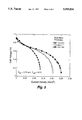
- FIG. 3 graphically depicts single cell fuel cell performance at different cathode flow field thicknesses.
- FIG. 4 graphically depicts the performance of an eight cell stack with 1.5 mm thick cathode flow fields.
- FIG. 5 graphically depicts the power yield of an eight cell stack with 1.5 mm thick cathode flow fields.
- a polymer electrolyte fuel cell is provided with the fuel supply outward from an axial central annulus and the oxygen supply inward from the cell periphery.
- PEC polymer electrolyte fuel cell
- circular flow-field and electrode plates are used to provide a symmetric configuration that is relatively lightweight and easy to manufacture.
- the fuel is hydrogen and the oxygen is oxygen in ambient air.
- the application of a diffusion process for the oxygen supply acts to limit the supply to the active sites, which limits the reaction.
- the porous flow-field also limits the outward diffusion of the reaction product water, thus minimizing water loss and drying effects on the cell. Since each molecule of oxygen diffusing inward produces two water molecules that diffuse outward at steady-state conditions, it will be appreciated that the cell design allows the influx of sufficient oxygen while limiting the escape of water vapor such that the system maintains the desired high hydration level.
- the absence of manifold seals at the periphery of all but the anode flow-fields and separator plates extending beyond the unit cell periphery to function as cooling fins allow greater conduction of reaction heat to the periphery to enhance cooling.
- the diffusion delivery of the reactants allows the performance of the cells to be relatively tolerant of stack orientation.
- Unit cell 10 includes catalyzed polymer electrolyte membrane assembly 12, e.g., a Dow or National membrane between porous electrodes, anode 13a and cathode 13b, such as a graphite cloth or paper, between fuel flow field plate 14 and oxygen flow field plate 18.
- Catalyzed polymer electrolyte membrane assembly 12 e.g., a Dow or National membrane between porous electrodes, anode 13a and cathode 13b, such as a graphite cloth or paper, between fuel flow field plate 14 and oxygen flow field plate 18.
- Fuel flow field plate 14 is provided with an outer seal 16 with anode 13a to prevent the release of fuel from the cell periphery.
- Oxygen flow field plate 18 is provided with an inner seal 22 with cathode 13b to separate it from the fuel annulus.
- end plate 24 is provided as a current collector plate and to compress the fuel cell components as discussed for FIG. 2.
- Fuel is introduced through port 28.
- a fuel diffusion flow field 29 with outer seal 31 is provided to distribute the fuel as described below.
- Bolt 26 extends through the fuel cell components along the fuel cell axis. Insulating sleeve 30 shrouds bolt shank 26 to electrically isolate bolt 26 from end plate 24. The entrance of bolt 26 through end plate 24 is sealed by the compression of O-ring 36 between washers 38a-d.
- Sleeve 32 forms an axial annular region about bolt 26 and acts as a distribution manifold to distribute fuel from fuel inlet flow field 29 axially along fuel cell 10.
- Sleeve 32 is preferably formed of a hydrophilic or hydrophilic-treated porous tube. The preferred design includes axial channels along the periphery. Fuel flow is along the channels to fuel flow field 14. Water accumulates in and is distributed along the cell by the wicking action of porous tube 32.
- Sleeve 32 is in communication with the inner edge of fuel flow field plate 14 in each fuel cell so that hydrogen is diffused along a surface of membrane 12 opposite the surface receiving oxygen that diffuses through oxygen flow field plate 18.
- Impermeable electrically conductive separator plate 34 separates flow fields in adjacent fuel cells when the cells are assembled into a stack. Separator plate 34 may extend radially from above the periphery of the stack to serve the additional function of a cooling fin.
- Fuel or anode flow field plate 14 is a macroporous electrically conductive material having a relatively small thickness, e.g., about 0.5 mm; oxygen or cathode flow field plate 18 is a macroporous electrically conductive material having a relatively large thickness, e.g., about 2 mm.
- a suitable flow field material is a carbon-fiber based paper with about 70% porosity and a 30 mm mean pore diameter, such as available as Spectracarb 2050 from Spectracorp. Inc., Lawrence, Mass.
- FIG. 2 depicts a cross-sectional view of an assembled fuel cell 40.
- Each unit fuel cell 42 includes air flow field plate 44 with its inner seal 46, catalyzed membrane assembly (membrane and electrode backings) 48, and fuel flow field plate 52 with outer seal 54, as discussed in FIG. 1.
- Inner seal 46 and outer seal 54 are not necessarily separate components, but may be formed by coating the appropriate edge portions with a sealant.
- Impermeable separator plates 56 separate adjacent unit fuel cells. As shown, separator plates 56 have an extended diameter to provide an additional function of a cooling fin during power generation.
- the stack assembly is formed by clamping unit cells 42 together by end plate 58 and a second end plate (not shown) at the other end of the assembled stack.
- the end plates must be relatively rigid and be electrically conductive. In one embodiment a two part configuration is used where a light weight aluminum plate is backed by a thin current collector.
- the end plates are clamped together by a single bolt 62 along the axis of all of the stack components.
- fuel inlet port 64 introduces fuel into fuel flow field 60 for diffusion to sleeve 66 for axial annular distribution to fuel flow fields 52 in unit fuel cells 42.
- Sleeve 66 is formed from an insulating material and electrically isolated from all of the individual stack plates.
- the head of bolt 62 bears against washer stack 68 to compress O-ring 67 for sealing the stack and for clamping the stack.
- Washer stack 68 may be any convenient arrangement that maintains the sealing and clamping force over a range of operating temperatures. Where the end plates are conductive, at least one of the washers in washer stack 68 is non-conductive in order to electrically isolate the end plate from bolt 62.
- the porous flow-fields could be metal screens or bonded particles; the membrane assembly could use any number of low or high platinum loading technologies; the flow-fields and impermeable barrier could be a single, monolithic bipolar plate, and so forth.
- FIG. 3 graphically illustrates the performance of a single unit fuel cell at different oxygen/cathode flow-field thicknesses of 1.5, 2.5, and 4.5 mm.
- the unit cells were formed from a polymer electrolyte membrane catalyzed with thin-film catalyst layers with low platinum loadings (about 0.15 mg Pt/cm 2 /electrode as described in U.S. Pat. Nos. 5,211,984 and 5,234,777, incorporated herein by reference).
- the catalyzed membranes were sandwiched between uncatalyzed ELAT backings (E-TEK, Inc., Natick, Mass.).
- the outside diameter of the hardware was about 5 cm and the cells had an active area of about 13 cm 2 .
- the cells were operated at an ambient pressure of about 0.75 atm (ambient pressure at laboratory elevation). Hydrogen fuel was supplied to the annular plenum at 5 psig.
- the porous flow fields were formed from Spectracarb 2050 material, described above. The cells provided steady long-term performance, indicating that the cells were maintaining a sufficiently high hydration level for the membranes. As shown in FIG. 3, the thicker flow-fields provided higher currents when the temperatures were controlled around 50° C. and delivered about a watt of power at about 0.5V.
- unit fuel cells are arranged in series to form a stack of cells for the delivery of more power and higher voltage.
- the concerns of overheating and hence sufficient hydration become more significant.
- FIG. 4 is shown a polarization curve of an eight cell stack for a cathode flow-field thickhesse of 1.5 mm. Every two cells were separated by impermeable stainless steel plates having a diameter of 6.4 cm vs. 5 cm for the unit cell and serve as cooling fins. The stack temperature rarely exceeded about 55° C. with the fins. The stack of unit cells is about 2 cm thick. The corresponding power output from the fuel cell stack is shown in FIG. 5. An output power up to 5 W was obtained at a cathode flow field thickness of 1.5 mm.
- the power densities of the stacks do not suffer as the thickness of the unit cells is decreased because it is then possible to fit in more cells per unit stack volume.
- the drawbacks are that the device voltage increases with the increased number of cells and the device cost increases because of the increased number of components. If the performance of the 1.5 mm cells is maintained over a multi-cell stack, then 25 W could be delivered from a device with 40 cells that is about 6.4 cm (2.5 in) in diameter (including fins) and is 8 cm long, not including the contributions of the endplates and bolt.
- a very compact package can be provided.
- an attractive package for using a small fuel cell system is a D-cell size stack combined with a metal hydride canister (HCl, Littleton, Colo.) that supplies 7.2 V, as is obtained from a six-pack of D-cell Nicad batteries.
- the sizes of the two systems are about the same, yet the fuel cell system yields more than three times more energy than the battery system (ca. 48 W hr vs. 15 W hr).
- a replacement hydride canister can be used immediately for continuous uninterrupted operation. It should be noted, however, that the fuel cell system is not capable of delivering power levels as high as nickel-cadmium batteries so it will not be an effective replacement for all applications.
Landscapes
- Life Sciences & Earth Sciences (AREA)
- Engineering & Computer Science (AREA)
- Manufacturing & Machinery (AREA)
- Sustainable Development (AREA)
- Sustainable Energy (AREA)
- Chemical & Material Sciences (AREA)
- Chemical Kinetics & Catalysis (AREA)
- Electrochemistry (AREA)
- General Chemical & Material Sciences (AREA)
- Fuel Cell (AREA)
Abstract
Description
Claims (16)
Priority Applications (1)
| Application Number | Priority Date | Filing Date | Title |
|---|---|---|---|
| US08/587,430 US5595834A (en) | 1995-09-01 | 1996-01-17 | Annular feed air breathing fuel cell stack |
Applications Claiming Priority (2)
| Application Number | Priority Date | Filing Date | Title |
|---|---|---|---|
| US08/522,885 US5514486A (en) | 1995-09-01 | 1995-09-01 | Annular feed air breathing fuel cell stack |
| US08/587,430 US5595834A (en) | 1995-09-01 | 1996-01-17 | Annular feed air breathing fuel cell stack |
Related Parent Applications (1)
| Application Number | Title | Priority Date | Filing Date |
|---|---|---|---|
| US08/522,885 Continuation-In-Part US5514486A (en) | 1995-09-01 | 1995-09-01 | Annular feed air breathing fuel cell stack |
Publications (1)
| Publication Number | Publication Date |
|---|---|
| US5595834A true US5595834A (en) | 1997-01-21 |
Family
ID=46250906
Family Applications (1)
| Application Number | Title | Priority Date | Filing Date |
|---|---|---|---|
| US08/587,430 Expired - Lifetime US5595834A (en) | 1995-09-01 | 1996-01-17 | Annular feed air breathing fuel cell stack |
Country Status (1)
| Country | Link |
|---|---|
| US (1) | US5595834A (en) |
Cited By (34)
| Publication number | Priority date | Publication date | Assignee | Title |
|---|---|---|---|---|
| US5851689A (en) * | 1997-01-23 | 1998-12-22 | Bechtel Corporation | Method for operating a fuel cell assembly |
| WO2000063996A1 (en) * | 1999-04-20 | 2000-10-26 | Manhattan Scientifics, Inc. | Device for compressing and supplying media to a stack of fuel cells and fuel cell stack with such a device |
| US6268077B1 (en) * | 1999-03-01 | 2001-07-31 | Motorola, Inc. | Portable fuel cell power supply |
| US6338492B1 (en) * | 1999-02-27 | 2002-01-15 | Firma Carl Freudenberg | Sealing system for large-surface thin parts |
| US6361892B1 (en) | 1999-12-06 | 2002-03-26 | Technology Management, Inc. | Electrochemical apparatus with reactant micro-channels |
| US6376116B1 (en) | 2000-05-12 | 2002-04-23 | Visteon Global Technologies, Inc. | Tubular polymeric membrane fuel cell system |
| US6399233B1 (en) | 1999-07-29 | 2002-06-04 | Technology Management, Inc. | Technique for rapid cured electrochemical apparatus component fabrication |
| US6423437B1 (en) | 2001-01-19 | 2002-07-23 | Enable Fuel Cell Corporation | Passive air breathing fuel cells |
| US20020098402A1 (en) * | 2001-01-25 | 2002-07-25 | Qinbai Fan | Air-breathing direct methanol fuel cell with metal foam current collectors |
| GB2373093A (en) * | 2001-03-09 | 2002-09-11 | Daido Metal Co | Portable fuel cell stacks |
| WO2002089244A1 (en) * | 2001-04-27 | 2002-11-07 | Enable Fuel Cell Corporation | Passive air breathing fuel cell system with switched fuel gas delivery |
| WO2002091513A1 (en) * | 2001-05-03 | 2002-11-14 | The Morgan Crucible Company Plc | Fuel cell or electrolyser construction |
| US20030165720A1 (en) * | 2002-03-04 | 2003-09-04 | Mti Microfuel Cells Inc. | Method and apparatus for water management of a fuel cell system |
| US20030180601A1 (en) * | 2002-03-22 | 2003-09-25 | Yukio Naruse | Air-breathing fuel cell stack |
| US20030180600A1 (en) * | 2002-03-22 | 2003-09-25 | Yukio Naruse | Split cell type fuel cell stack |
| US20040043281A1 (en) * | 2002-08-29 | 2004-03-04 | Daido Metal Company Ltd. | Airbreathing fuel cell |
| US20040053108A1 (en) * | 2002-08-28 | 2004-03-18 | Honda Giken Kogyo Kabushiki Kaisha | Fuel cell |
| US20040053106A1 (en) * | 2002-07-05 | 2004-03-18 | Daido Metal Company Ltd. | Airbreathing fuel cell |
| US20040106033A1 (en) * | 2002-11-21 | 2004-06-03 | Daido Metal Company Ltd. | Airbreathing fuel cell |
| US20040234837A1 (en) * | 2003-05-19 | 2004-11-25 | Honda Motor Co., Ltd. | Fuel cell |
| US20050158593A1 (en) * | 2002-04-19 | 2005-07-21 | Imazato Minehisa | Formation water treating system and formation water treating method, and power generator |
| US20050221152A1 (en) * | 2002-06-24 | 2005-10-06 | Turpin Mark C | Flow field plate geometries |
| US20060134499A1 (en) * | 2004-12-22 | 2006-06-22 | Honda Motor Co., Ltd. | Fuel cell system |
| US7067213B2 (en) | 2001-02-12 | 2006-06-27 | The Morgan Crucible Company Plc | Flow field plate geometries |
| US20070105000A1 (en) * | 2003-06-18 | 2007-05-10 | The Morgan Crucible Company Plc | Flow field plate geometries |
| WO2007128202A1 (en) | 2006-04-26 | 2007-11-15 | Binglun Tian | A fuel cell pile without terminal plates suitable for low temperature operation |
| US20080008917A1 (en) * | 2004-12-22 | 2008-01-10 | Hiroki Homma | Fuel Cell System |
| WO2008106824A1 (en) * | 2007-03-06 | 2008-09-12 | Golden Energy Fuel Cell Co., Ltd. | Fuel cell |
| US20090263700A1 (en) * | 2008-04-17 | 2009-10-22 | Us Government As Represented By Secretary Of The Army | Fuel cell assembly |
| US10062913B2 (en) | 2012-08-14 | 2018-08-28 | Loop Energy Inc. | Fuel cell components, stacks and modular fuel cell systems |
| US10686199B2 (en) | 2012-08-14 | 2020-06-16 | Loop Energy Inc. | Fuel cell flow channels and flow fields |
| US10930942B2 (en) | 2016-03-22 | 2021-02-23 | Loop Energy Inc. | Fuel cell flow field design for thermal management |
| US11060195B2 (en) | 2012-08-14 | 2021-07-13 | Loop Energy Inc. | Reactant flow channels for electrolyzer applications |
| US11309569B1 (en) | 2018-09-12 | 2022-04-19 | Triad National Security, Llc | Microwatt fuel cell stack |
Citations (7)
| Publication number | Priority date | Publication date | Assignee | Title |
|---|---|---|---|---|
| US4824742A (en) * | 1988-04-21 | 1989-04-25 | The United States Department Of Energy | Manifold, bus support and coupling arrangement for solid oxide fuel cells |
| US5158837A (en) * | 1990-02-15 | 1992-10-27 | Ngk Insulators, Ltd. | Solid oxide fuel cells |
| US5176967A (en) * | 1990-02-15 | 1993-01-05 | Ngk Insulators, Ltd. | Solid oxide fuel cells |
| US5185219A (en) * | 1990-02-15 | 1993-02-09 | Ngk Insulators, Ltd. | Solid oxide fuel cells |
| US5186806A (en) * | 1990-12-31 | 1993-02-16 | California Institute Of Technology | Ceramic distribution members for solid state electrolyte cells and method of producing |
| US5211984A (en) * | 1991-02-19 | 1993-05-18 | The Regents Of The University Of California | Membrane catalyst layer for fuel cells |
| US5234777A (en) * | 1991-02-19 | 1993-08-10 | The Regents Of The University Of California | Membrane catalyst layer for fuel cells |
-
1996
- 1996-01-17 US US08/587,430 patent/US5595834A/en not_active Expired - Lifetime
Patent Citations (7)
| Publication number | Priority date | Publication date | Assignee | Title |
|---|---|---|---|---|
| US4824742A (en) * | 1988-04-21 | 1989-04-25 | The United States Department Of Energy | Manifold, bus support and coupling arrangement for solid oxide fuel cells |
| US5158837A (en) * | 1990-02-15 | 1992-10-27 | Ngk Insulators, Ltd. | Solid oxide fuel cells |
| US5176967A (en) * | 1990-02-15 | 1993-01-05 | Ngk Insulators, Ltd. | Solid oxide fuel cells |
| US5185219A (en) * | 1990-02-15 | 1993-02-09 | Ngk Insulators, Ltd. | Solid oxide fuel cells |
| US5186806A (en) * | 1990-12-31 | 1993-02-16 | California Institute Of Technology | Ceramic distribution members for solid state electrolyte cells and method of producing |
| US5211984A (en) * | 1991-02-19 | 1993-05-18 | The Regents Of The University Of California | Membrane catalyst layer for fuel cells |
| US5234777A (en) * | 1991-02-19 | 1993-08-10 | The Regents Of The University Of California | Membrane catalyst layer for fuel cells |
Non-Patent Citations (4)
| Title |
|---|
| J. K. Neutzler et al., "Development of a Portable, Air-Breathing Polymer Electrolyte Fuel Cell Stack," printed in Extended Abstracts, Electrochemical Society Meeting, vol. 94-2, p. 961 (Oct. 1994). |
| J. K. Neutzler et al., Development of a Portable, Air Breathing Polymer Electrolyte Fuel Cell Stack, printed in Extended Abstracts, Electrochemical Society Meeting, vol. 94 2, p. 961 (Oct. 1994). * |
| K. Prater, "Solid polymer fuel cell developments at Ballard" Journal of Power Sources, 37, 181-188 (1992) (Month not avail). |
| K. Prater, Solid polymer fuel cell developments at Ballard Journal of Power Sources, 37, 181 188 (1992) (Month not avail). * |
Cited By (61)
| Publication number | Priority date | Publication date | Assignee | Title |
|---|---|---|---|---|
| US6274258B1 (en) | 1997-01-23 | 2001-08-14 | Nexant, Inc. | Fuel cell assembly |
| US5851689A (en) * | 1997-01-23 | 1998-12-22 | Bechtel Corporation | Method for operating a fuel cell assembly |
| US6338492B1 (en) * | 1999-02-27 | 2002-01-15 | Firma Carl Freudenberg | Sealing system for large-surface thin parts |
| US6268077B1 (en) * | 1999-03-01 | 2001-07-31 | Motorola, Inc. | Portable fuel cell power supply |
| WO2000063996A1 (en) * | 1999-04-20 | 2000-10-26 | Manhattan Scientifics, Inc. | Device for compressing and supplying media to a stack of fuel cells and fuel cell stack with such a device |
| US6399233B1 (en) | 1999-07-29 | 2002-06-04 | Technology Management, Inc. | Technique for rapid cured electrochemical apparatus component fabrication |
| US20020132156A1 (en) * | 1999-12-06 | 2002-09-19 | Technology Management, Inc. | Electrochemical apparatus with reactant micro-channels |
| US6361892B1 (en) | 1999-12-06 | 2002-03-26 | Technology Management, Inc. | Electrochemical apparatus with reactant micro-channels |
| US6878480B2 (en) | 1999-12-06 | 2005-04-12 | Technology Management, Inc. | Electrochemical apparatus with reactant micro-channels |
| US6376116B1 (en) | 2000-05-12 | 2002-04-23 | Visteon Global Technologies, Inc. | Tubular polymeric membrane fuel cell system |
| US6423437B1 (en) | 2001-01-19 | 2002-07-23 | Enable Fuel Cell Corporation | Passive air breathing fuel cells |
| WO2002058180A1 (en) * | 2001-01-19 | 2002-07-25 | Enable Fuel Cell Corporation | Passive air breathing fuel cells |
| US20020098402A1 (en) * | 2001-01-25 | 2002-07-25 | Qinbai Fan | Air-breathing direct methanol fuel cell with metal foam current collectors |
| US6797422B2 (en) * | 2001-01-25 | 2004-09-28 | Gas Technology Institute | Air-breathing direct methanol fuel cell with metal foam current collectors |
| US7067213B2 (en) | 2001-02-12 | 2006-06-27 | The Morgan Crucible Company Plc | Flow field plate geometries |
| GB2373093A (en) * | 2001-03-09 | 2002-09-11 | Daido Metal Co | Portable fuel cell stacks |
| US20020127453A1 (en) * | 2001-03-09 | 2002-09-12 | Daido Metal Company Ltd. | Portable fuel cell stack |
| GB2373093B (en) * | 2001-03-09 | 2003-05-14 | Daido Metal Co | Portable fuel cell stacks |
| US6773843B2 (en) | 2001-03-09 | 2004-08-10 | Daido Metal Company Ltd. | Portable fuel cell stack |
| WO2002089244A1 (en) * | 2001-04-27 | 2002-11-07 | Enable Fuel Cell Corporation | Passive air breathing fuel cell system with switched fuel gas delivery |
| US20040142225A1 (en) * | 2001-05-03 | 2004-07-22 | Turpin Mark Christopher | Fuel cell or electrolyser construction |
| WO2002091513A1 (en) * | 2001-05-03 | 2002-11-14 | The Morgan Crucible Company Plc | Fuel cell or electrolyser construction |
| US20070015032A1 (en) * | 2002-03-04 | 2007-01-18 | Mti Microfuel Cells, Inc. | Method and apparatus for water management of a fuel cell system |
| US20030165720A1 (en) * | 2002-03-04 | 2003-09-04 | Mti Microfuel Cells Inc. | Method and apparatus for water management of a fuel cell system |
| US6824900B2 (en) | 2002-03-04 | 2004-11-30 | Mti Microfuel Cells Inc. | Method and apparatus for water management of a fuel cell system |
| DE10312664B4 (en) * | 2002-03-22 | 2006-11-23 | Daido Metal Co., Ltd. | Air breathing fuel cell stack |
| US20030180600A1 (en) * | 2002-03-22 | 2003-09-25 | Yukio Naruse | Split cell type fuel cell stack |
| US7008712B2 (en) * | 2002-03-22 | 2006-03-07 | Daido Metal Company Ltd. | Split cell type fuel cell stack |
| US20030180601A1 (en) * | 2002-03-22 | 2003-09-25 | Yukio Naruse | Air-breathing fuel cell stack |
| US20050158593A1 (en) * | 2002-04-19 | 2005-07-21 | Imazato Minehisa | Formation water treating system and formation water treating method, and power generator |
| US7816043B2 (en) * | 2002-04-19 | 2010-10-19 | Sony Corporation | Water disposal system, method of disposing water, and power generation apparatus |
| US20050221152A1 (en) * | 2002-06-24 | 2005-10-06 | Turpin Mark C | Flow field plate geometries |
| US7838139B2 (en) | 2002-06-24 | 2010-11-23 | The Morgan Crucible Company Plc | Flow field plate geometries |
| US20040053106A1 (en) * | 2002-07-05 | 2004-03-18 | Daido Metal Company Ltd. | Airbreathing fuel cell |
| US7316853B2 (en) | 2002-07-05 | 2008-01-08 | Daido Metal Company Ltd. | Airbreathing fuel cell |
| US20040053108A1 (en) * | 2002-08-28 | 2004-03-18 | Honda Giken Kogyo Kabushiki Kaisha | Fuel cell |
| US7122267B2 (en) * | 2002-08-28 | 2006-10-17 | Honda Giken Kogyo Kabushiki Kaisha | Fuel cell configured with discharge passages that preheat fuel gas and prevent cross leakage |
| US7455926B2 (en) | 2002-08-29 | 2008-11-25 | Daido Metal Company Ltd. | Airbreathing fuel cell |
| US20040043281A1 (en) * | 2002-08-29 | 2004-03-04 | Daido Metal Company Ltd. | Airbreathing fuel cell |
| US7118823B2 (en) | 2002-11-21 | 2006-10-10 | Daido Metal Company | Airbreathing fuel cell |
| US20040106033A1 (en) * | 2002-11-21 | 2004-06-03 | Daido Metal Company Ltd. | Airbreathing fuel cell |
| US20040234837A1 (en) * | 2003-05-19 | 2004-11-25 | Honda Motor Co., Ltd. | Fuel cell |
| US7622214B2 (en) * | 2003-05-19 | 2009-11-24 | Honda Motor Co., Ltd. | Fuel cell capable of preventing anode oxidation |
| US20070105000A1 (en) * | 2003-06-18 | 2007-05-10 | The Morgan Crucible Company Plc | Flow field plate geometries |
| US8197985B2 (en) * | 2004-12-22 | 2012-06-12 | Honda Motor Co., Ltd. | Fuel cell system with load applying mechanism |
| US20080008917A1 (en) * | 2004-12-22 | 2008-01-10 | Hiroki Homma | Fuel Cell System |
| US8273492B2 (en) * | 2004-12-22 | 2012-09-25 | Honda Motor Co., Ltd. | Load applying mechanism in a fuel cell system |
| US20060134499A1 (en) * | 2004-12-22 | 2006-06-22 | Honda Motor Co., Ltd. | Fuel cell system |
| WO2007128202A1 (en) | 2006-04-26 | 2007-11-15 | Binglun Tian | A fuel cell pile without terminal plates suitable for low temperature operation |
| WO2008106824A1 (en) * | 2007-03-06 | 2008-09-12 | Golden Energy Fuel Cell Co., Ltd. | Fuel cell |
| CN101485020B (en) * | 2007-03-06 | 2011-10-26 | 北京金能燃料电池有限公司 | The fuel cell |
| US20090263700A1 (en) * | 2008-04-17 | 2009-10-22 | Us Government As Represented By Secretary Of The Army | Fuel cell assembly |
| US10062913B2 (en) | 2012-08-14 | 2018-08-28 | Loop Energy Inc. | Fuel cell components, stacks and modular fuel cell systems |
| US10686199B2 (en) | 2012-08-14 | 2020-06-16 | Loop Energy Inc. | Fuel cell flow channels and flow fields |
| US10734661B2 (en) | 2012-08-14 | 2020-08-04 | Loop Energy Inc. | Fuel cell components, stacks and modular fuel cell systems |
| US11060195B2 (en) | 2012-08-14 | 2021-07-13 | Loop Energy Inc. | Reactant flow channels for electrolyzer applications |
| US11489175B2 (en) | 2012-08-14 | 2022-11-01 | Loop Energy Inc. | Fuel cell flow channels and flow fields |
| US12227855B2 (en) | 2012-08-14 | 2025-02-18 | Loop Energy Inc. | Reactant flow channels for electrolyzer applications |
| US10930942B2 (en) | 2016-03-22 | 2021-02-23 | Loop Energy Inc. | Fuel cell flow field design for thermal management |
| US11901591B2 (en) | 2016-03-22 | 2024-02-13 | Loop Energy Inc. | Fuel cell flow field design for thermal management |
| US11309569B1 (en) | 2018-09-12 | 2022-04-19 | Triad National Security, Llc | Microwatt fuel cell stack |
Similar Documents
| Publication | Publication Date | Title |
|---|---|---|
| US5514486A (en) | Annular feed air breathing fuel cell stack | |
| US5595834A (en) | Annular feed air breathing fuel cell stack | |
| US5641586A (en) | Fuel cell with interdigitated porous flow-field | |
| US4826741A (en) | Ion exchange fuel cell assembly with improved water and thermal management | |
| US10734661B2 (en) | Fuel cell components, stacks and modular fuel cell systems | |
| US4839247A (en) | Static regenerative fuel cell system for use in space | |
| JP3352716B2 (en) | Solid polymer electrolyte fuel cell device | |
| US5262249A (en) | Internally cooled proton exchange membrane fuel cell device | |
| EP0664928B1 (en) | Lightweight fuel cell membrane electrode assembly with integral reactant flow passages | |
| US5972530A (en) | Air-cooled, hydrogen-air fuel cell | |
| US5952119A (en) | Fuel cell membrane humidification | |
| JP3841347B2 (en) | Polymer electrolyte fuel cell | |
| JP4954411B2 (en) | Polymerized membrane fuel cell assembly | |
| US20070015035A1 (en) | Lightweight direct methanol fuel cell and supporting systems | |
| US7678490B2 (en) | Polymer electrolyte fuel cell | |
| CN1181586C (en) | Wetting device for polymer membrane fuel cell | |
| US7232582B2 (en) | Fuel cell | |
| US10998571B2 (en) | High-voltage fuel-cell stack | |
| WO2002058180A1 (en) | Passive air breathing fuel cells | |
| US20030124407A1 (en) | Fuel cell stack | |
| US7396602B2 (en) | Electrochemical generator and method for its utilisation | |
| JP3477926B2 (en) | Solid polymer electrolyte fuel cell | |
| US6312845B1 (en) | Macroporous flow field assembly | |
| EP1294037B1 (en) | A fuel cell stack and a method of supplying reactant gases to the fuel cell stack | |
| JPH05251097A (en) | Solid polymer electrolyte fuel cell |
Legal Events
| Date | Code | Title | Description |
|---|---|---|---|
| AS | Assignment |
Owner name: REGENTS OF THE UNIVERSITY OF CALIFORNIA, THE, NEW Free format text: ASSIGNMENT OF ASSIGNORS INTEREST;ASSIGNORS:WILSON, MAHLON S.;NEUTZLER, JAY K.;REEL/FRAME:007876/0548 Effective date: 19960116 |
|
| STCF | Information on status: patent grant |
Free format text: PATENTED CASE |
|
| FEPP | Fee payment procedure |
Free format text: PAT HLDR NO LONGER CLAIMS SMALL ENT STAT AS NONPROFIT ORG (ORIGINAL EVENT CODE: LSM3); ENTITY STATUS OF PATENT OWNER: LARGE ENTITY |
|
| FPAY | Fee payment |
Year of fee payment: 4 |
|
| FPAY | Fee payment |
Year of fee payment: 8 |
|
| AS | Assignment |
Owner name: LOS ALAMOS NATIONAL SECURITY, LLC, NEW MEXICO Free format text: ASSIGNMENT OF ASSIGNORS INTEREST;ASSIGNOR:REGENTS OF THE UNIVERSITY OF CALIFORNIA, THE;REEL/FRAME:017897/0936 Effective date: 20060410 |
|
| REMI | Maintenance fee reminder mailed | ||
| FPAY | Fee payment |
Year of fee payment: 12 |
|
| SULP | Surcharge for late payment |
Year of fee payment: 11 |