US5572975A - Device and method of regulating the start of fuel injection in an otto engine - Google Patents
Device and method of regulating the start of fuel injection in an otto engine Download PDFInfo
- Publication number
- US5572975A US5572975A US08/362,558 US36255895A US5572975A US 5572975 A US5572975 A US 5572975A US 36255895 A US36255895 A US 36255895A US 5572975 A US5572975 A US 5572975A
- Authority
- US
- United States
- Prior art keywords
- injection
- fuel
- engine
- time
- inlet valve
- Prior art date
- Legal status (The legal status is an assumption and is not a legal conclusion. Google has not performed a legal analysis and makes no representation as to the accuracy of the status listed.)
- Expired - Lifetime
Links
Images

Classifications
-
- F—MECHANICAL ENGINEERING; LIGHTING; HEATING; WEAPONS; BLASTING
- F02—COMBUSTION ENGINES; HOT-GAS OR COMBUSTION-PRODUCT ENGINE PLANTS
- F02D—CONTROLLING COMBUSTION ENGINES
- F02D41/00—Electrical control of supply of combustible mixture or its constituents
- F02D41/30—Controlling fuel injection
- F02D41/32—Controlling fuel injection of the low pressure type
-
- F—MECHANICAL ENGINEERING; LIGHTING; HEATING; WEAPONS; BLASTING
- F02—COMBUSTION ENGINES; HOT-GAS OR COMBUSTION-PRODUCT ENGINE PLANTS
- F02D—CONTROLLING COMBUSTION ENGINES
- F02D41/00—Electrical control of supply of combustible mixture or its constituents
- F02D41/24—Electrical control of supply of combustible mixture or its constituents characterised by the use of digital means
- F02D41/26—Electrical control of supply of combustible mixture or its constituents characterised by the use of digital means using computer, e.g. microprocessor
- F02D41/263—Electrical control of supply of combustible mixture or its constituents characterised by the use of digital means using computer, e.g. microprocessor the program execution being modifiable by physical parameters
-
- F—MECHANICAL ENGINEERING; LIGHTING; HEATING; WEAPONS; BLASTING
- F02—COMBUSTION ENGINES; HOT-GAS OR COMBUSTION-PRODUCT ENGINE PLANTS
- F02D—CONTROLLING COMBUSTION ENGINES
- F02D41/00—Electrical control of supply of combustible mixture or its constituents
- F02D41/30—Controlling fuel injection
- F02D41/32—Controlling fuel injection of the low pressure type
- F02D41/34—Controlling fuel injection of the low pressure type with means for controlling injection timing or duration
- F02D41/345—Controlling injection timing
-
- F—MECHANICAL ENGINEERING; LIGHTING; HEATING; WEAPONS; BLASTING
- F02—COMBUSTION ENGINES; HOT-GAS OR COMBUSTION-PRODUCT ENGINE PLANTS
- F02B—INTERNAL-COMBUSTION PISTON ENGINES; COMBUSTION ENGINES IN GENERAL
- F02B1/00—Engines characterised by fuel-air mixture compression
- F02B1/02—Engines characterised by fuel-air mixture compression with positive ignition
- F02B1/04—Engines characterised by fuel-air mixture compression with positive ignition with fuel-air mixture admission into cylinder
-
- F—MECHANICAL ENGINEERING; LIGHTING; HEATING; WEAPONS; BLASTING
- F02—COMBUSTION ENGINES; HOT-GAS OR COMBUSTION-PRODUCT ENGINE PLANTS
- F02D—CONTROLLING COMBUSTION ENGINES
- F02D2250/00—Engine control related to specific problems or objectives
- F02D2250/12—Timing of calculation, i.e. specific timing aspects when calculation or updating of engine parameter is performed
-
- Y—GENERAL TAGGING OF NEW TECHNOLOGICAL DEVELOPMENTS; GENERAL TAGGING OF CROSS-SECTIONAL TECHNOLOGIES SPANNING OVER SEVERAL SECTIONS OF THE IPC; TECHNICAL SUBJECTS COVERED BY FORMER USPC CROSS-REFERENCE ART COLLECTIONS [XRACs] AND DIGESTS
- Y02—TECHNOLOGIES OR APPLICATIONS FOR MITIGATION OR ADAPTATION AGAINST CLIMATE CHANGE
- Y02T—CLIMATE CHANGE MITIGATION TECHNOLOGIES RELATED TO TRANSPORTATION
- Y02T10/00—Road transport of goods or passengers
- Y02T10/10—Internal combustion engine [ICE] based vehicles
- Y02T10/40—Engine management systems
Definitions
- This invention relates to a device and method for regulating the start of fuel injection in an internal combustion engine.
- patent Application No. 5,048,500 describes a heating plate which can be swivelled into the air flow and is arranged upstream of the inlet valve, but where the fuel nozzle is directed toward the heating plate arranged in the intake duct upstream from the inlet valve.
- the invention is applied advantageously to Otto engines with electronic, computerized control of preferably sequential fuel injection.
- the object of this invention is to ensure that most of the fuel is injected to the inlet valve of the internal combustion engine, so-called indirect injection, immediately before the inlet valve begins to open, enabling a high proportion of the evaporation heat prevailing along the walls of the intake duct to be used for evaporating the fuel.
- the fuel is preferably injected to the valve rod close to valve head, or directly on to the valve head on the respective inlet valves, as a result of which the hottest sections, close to the combustion space, receive a shower of fuel which improves the evaporation and atomization of the fuel before the opening of the inlet valve.
- the device means for determining the stroke position of the engine, fuel injection means selectively activatable during respective cycles of the engine for injecting fuel towards the inlet valve, and control means for controlling the activation and deactivation of the fuel injection means in accordance with a fuel amount demand.
- the control means includes a memory for storing the fuel amount demand during one cycle of operation as a base value.
- the control means activates the fuel injection means at a subsequent cycle of operation of the engine at a predetermined stroke position of the engine as determined by the stored base value and deactivates the injection means when the inlet valve begins to open.
- the method according to the invention comprises determining a predetermined injection time prior to activation of the injection means, and activating the injection means for a time period equal to the predetermined injection time and in advance of the opening of the inlet valve such that the predetermined injection time is substantially completed when the inlet valve opens.
- the calculating capacity of the computer is prevented from being tied up in continuous checking and calculating to determine whether the fuel demand has changed.
- the base value stored in the memory is continuously updated with a value corresponding to the fuel amount demand of the last completed injection of fuel by the fuel injection means.
- the predetermined injection time is continuously updated with the last completed injection time.
- a further object is to reduce the calculation work required to calculate the fuel flow rate for each injection, yet ensure that most of the fuel supplied is injected to a closed valve, thereby releasing the calculating capacity of the injection system for other purposes and enabling cheaper microcomputers with slower calculating capacity to be used for the injection systems.
- the invention also provides improved facilities for integrating computer controllable engine functions other than the fuel system since the fuel amount calculation for each injection need only be calculated a limited number of times, preferably no more than twice, whilst still being aisle to obtain a fuel amount which is demanded by the instantaneous engine parameters. Other computer controlled functions may then be monitored, such as ignition system, charging pressure regulating system, and possibly also computer controlled gear changing, without impairing the fuel flow rate calculation.
- a further object is that of being able to correct, tire fuel amount if a transient load case occurs between the previous injection and the current injection, based on previous injection.
- FIG. 1 shows an internal combustion engine with an injection system according to the invention.
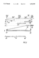
- FIG. 2 shows a sequence diagram of events and measures taken during a four-stroke working cycle of one cylinder.
- FIG. 1 shows an injection system for an internal combustion engine 1 of the Otto type.
- the combustion engine comprises at least one cylinder 12 with a piston 13 arranged in it, which piston drives a crankshaft.
- the combustion space of the cylinder is fed with a fuel-air mixture in the intake stroke via inlet valve 14, which is opened with a camshaft 16.
- inlet valve 14 which is opened with a camshaft 16.
- exhaust valve 15 is opened with camshaft 17.
- the injection system is supplied with fuel via a preferably electrically driven fuel pump 9, which in practice is arranged in fuel tank 8, and which sucks fuel from the tank via a feed pump 32, and feeds it on to a fuel distribution pipe 5 via a filter 31.
- a number of fuel pipes 6 branches off from the fuel distribution pipe for each of the injectors 21 arranged in the inlet duct 20 of the respective cylinders.
- the pressure level in the fuel distribution pipe is determined by a pressure regulator 7, which keeps the fuel pressure constant in relation to the pressure in the engine intake manifold. This ensures that the injected quantity of fuel is not affected by the variable pressure in the intake manifold but only by the time during which the injector is open.
- Injector 21 consists of a conventional injection valve, preferably an electrically controlled magnetic valve of the solenoid type, mounted in the inlet ducts of the respective cylinders close to and directed towards the respective inlet valves 14.
- the injector is directed so that the fuel jet hits the valve rod close to the valve head, or is directed directly on to the valve head on inlet valve 14. Because the fuel hits the valve and is dispersed over the valve head, the surface heated by the combustion in the cylinder is used for evaporating the fuel.
- the valve head is also heated very quickly when cold starting, essentially just as quickly as the electrically heated heating plates of the PTC type, produced for improved atomization/evaporation of the fuel for cold start. If engine 1 is fitted with two inlet valves 14 per cylinder, an injector with two injection ports is used, these ports being directed towards their own individual inlet valves to ensure that the largest possible heated area is obtained for the quantity of injected fuel required.
- the injector opening time is controlled by a control unit 10 on the basis of a number of engine parameters detected by the control unit, representing toad, speed, engine temperature, mass of air sucked in and oxygen content of the exhaust gases.
- Control unit 10 is connected by a network of cables 40 to several transmitters for detecting the engine parameters, and to actuators which can be actuated for operation of the engine, and receives its power supply from a battery 33 via an ignition lock 45.
- the cable network also includes relays 43, 44 for the control device and fuel pump.
- Control unit 10 consists of a microcomputer based unit incorporating means for storing data in memory 34, arithmetical calculation of speed and the required quantity of fuel 35, as well as an interrupt register 38.
- the control unit receives information via the cable network 40 on the mass of air sucked in via an air mass meter 24 arranged upstream of the inlet pipe common to the cylinders, and via throttle 22 arranged before it.
- Air mass meter 24 may be of the conventional heated-wire type, where the resistance in the air rewound heated wire gives a direct measure of the mass of air sucked in.
- a pressure transducer can be arranged in the inlet pipe downstream from throttle 22, together with an air temperature gauge arranged upstream from throttle 22. The pressure and air temperature detected thereby can be used instead of air mass meter 24 for calculating the mass of air sucked in.
- Temperature gauge 36 transmits a continuous signal of the engine temperature directly to control unit 10.
- a lambda probe 37 which detects the oxygen content of the exhaust gases, is arranged in the exhaust manifold 18 of the engine, enabling control unit 10 to correct the fuel-air mixture given by the mass of air sucked in and the load, so that the optimum mixing ratio for the catalytic converter can be maintained.
- Control unit 10 also receives information on the engine crankshaft position.
- a transmitter 29 arranged on the flywheel detects reference markings 30 on a code disc 28 co-rotating with the flywheel.
- At least two reference markings 30 are required, offset 180 degrees to the code disc, for detecting the top dead center (TDC) of the respective pairs of pistons, together with an extra marking 39 for distinguishing which pair of pistons is at the top dead center.
- the extra marking 39 is located immediately before either of markings 30, and has a much smaller gap which results in a shorter distinguishable signal from transmitter 29, as opposed to the signal generated by markings 30.
- a camshaft transmitter 27 is also used. This transmitter is suitably arranged in an ignition distributor 26, which is driven by a camshaft 17.
- an ion current sensor in the cylinder preferably a sensor where the spark plug gap is used as the sensor device, can detect the cylinders in which combustion is taking place. These methods can be used to determine the ignition sequence, which is then used for sequential activation of the spark plug and injectors so that ignition and injection take place sequentially in the correct stroke position on the engine for the respective cylinders.
- the fuel control system must be capable of detecting and handling engine parameter data which are as up to date and accurately measured as possible. Because of the stringent requirements regarding emissions, among other things, for which the system has been designed, it is not only the signal quality which is important. The actual measuring and regulating strategy will also determine the final result.
- the length of the injection time, and hence the fuel amount are primarily a function of instantaneous engine parameters such as inlet pipe pressure, air temperature, throttle position and throttle movement, and several other correcting engine parameters such as engine temperature, starting conditions and oxygen content of the exhaust gases.
- the engine parameters are measured at different times and at different intervals. Temperatures are measured with slow updating and effective mean value formation.
- Engine parameter data such as inlet pipe pressure and throttle position are frequently updated, several times per engine revolution, on the basis of special strategies, to ensure a rapid response to throttle-up or throttle-down movements initiated by the driver.
- the fuel amount required when the engine operation has been established, after the starting process, and calculated on the basis of detected instantaneous engine parameters, is stored in a memory 34 in control device 10.
- Memory 10 may possibly contain a number of memory addresses corresponding to the number of cylinders.
- the last completed injection time for the cylinder in question is continuously stored in these addresses for the respective cylinders, and before the next injection the injection time which was last applicable to the cylinder in question is collected from the respective memory addresses.
- This injection time forms a base value for the injection time, this base value being used as a preliminary predetermined injection time when activating the injector.
- the start timing of injection also affects performances and emissions.
- Several solutions have been developed in terms of bow the start timing of injection should be synchronized in relation to the compression stroke of the engine.
- the injection has been synchronized so that it takes place at least to a certain extent during a period of time in which the inlet valve has opened. In this way the fuel is thought to be entrained by the air flow past the injector and on into the cylinder.
- the disadvantage in this case is that if the injector has difficulty in atomizing the fuel, relatively large drops of fuel reach the cylinder, resulting in incomplete combustion of the fuel drop.
- the start of injection can be initiated so that the injection is largely completed by the time inlet valve 14 is to open.
- This enables most of the fuel to be injected onto a not inlet valve 14 so that the heat can be absorbed, and for easier evaporation and atomization in the air sucked in by the motor during subsequent inlet valve opening.
- This provides a more homogeneous fuel-air mixture, which results in more complete combustion of the fuel supplied.
- FIG. 2 shows a sequence diagram of different events A-B and measures C-D taken during a four-stroke cycle for a particular cylinder.
- A shows when inlet valve 14 is kept open over crankshaft range 51
- B shows when outlet valve 15 is kept open over crankshaft range 52.
- C shows how a measurement of the instantaneous engine parameters prevailing during a corresponding period of time is carried out within crankshaft range 53. Either detected values give rise to an updating of mean value formed data, as previously indicated, or other values are updated directly for fast response without any weighting or mean value formation, which values are stored in memory 34 of control unit 10.
- D shows when the injection valve is kept open, its opening being controlled by reference position 50, determined by the start of the opening of the inlet valve.
- E and F show on an enlarged scale injection interval D, where 61 denotes the opening time and 60 the closing time.
- a variant is shown where the measurement within crankshaft range 53 has given rise to a reduction in the required fuel flow rate, enabling closing to take place in an earlier position 60'.
- the markings are used both for calculating the speed, which indicates the time delay until the arrival of the next TDC marking 30, and for creating an interrupt in an interrupt function when a position before TDC is reached when an injection is to begin.
- the speed indicated the time required until the fixed position 50 in the compression stroke is reached for the opening of inlet valve 14 can be determined by a simple arithmetic calculation, in normal. load cases it is desirable to ensure that most of the fuel is injected out to the closed valve, thus enabling the hot valve head to evaporate the fuel, injection to the open valve is only required in extreme load cases which may arise, for example, during vigorous accelerations, when it is necessary to feed as much fuel as possible into the cylinder, and in certain cold start cases.
- an injection start time is obtained which is stored in interrupt register 38.
- the injection time last completed, and used for controlling the injection time can either consist of the injection time last completed for the respective cylinder, or of the injection time last completed in the injection sequence.
- an interrupt is generated which opens the fuel valve automatically with a predetermined injection time lapsed on a previous calculation, appropriately the injection time which was applicable to the injection last completed.
- the injection time last completed and used for calculating the fuel amount can either consist of the injection time last completed for the respective cylinder or the injection time last completed in the injection sequence.
- the time value stored in interrupt register 38 is corrected. If necessary a correction can only be carried out if the difference is substantial and exceeds a predetermined threshold value between the predetermined fuel amount and the fuel amount demanded by the instantaneous engine parameters detected during interval 53 of the crankshaft revolution. The system then resumes other tasks whilst the injection valve remains open.
- interrupt register 38 When the required injection time stored in interrupt register 38 has expired at position 60, a new interrupt is generated. During this interrupt generation the injector is first commanded to close, whereupon the system immediately checks whether there has been a throttle movement since the last injection time calculation, carried out when the injector opened, which movement would indicate a commanded acceleration and fuel enrichment. If this is the case a second additional calculation of the instantaneously demanded fuel enrichment requirement begins.
- the fuel enrichment requirement is calculated as a function of the most significant engine parameters for this, such as at least throttle position, throttle derivatives and engine temperature.
- the time taken for this fuel enrichment calculation lies in the 100 microsecond range, which means that a conventional electromechanical valve does not nave time to begin closing before the calculation is complete.
- Such a complete fuel flow rate calculation calculates and corrects the fuel flow rate on the basis of all the detected engine parameters which may influence the required fuel flow rate. These may include load (i.e. air mass), speed, lambda value, engine temperature, after-start conditions (enrichment), temperature corrections and idling adjustment.
- the full fuel flow rate calculation can be comfortably completed after the injector has opened and before the injector closes.
- specific load cases such as decelerations (engine braking)
- the injection time is negligible bed use there is no actual fuel demand
- the base injection value stored in the memory is updated for use as the predetermined injection time before the next injection, when one complete calculation of the fuel amount is carried out in parallel with the opening of the valve.
- the second additional fuel flow rate calculation which is initiated immediately after the commanded closing of the injector, only uses the parameters most indicative of increased load for calculating the fuel enrichment. These parameters consist primarily of throttle position and throttle derivatives, and secondarily of the engine temperature, and the load enrichment requirement is calculated with these parameters on the basis of hundreds of instructions in the computer of control unit 10, which instructions are run through in something like 100 microseconds.
- interrupt register 38 When a required additional injection time is calculated with a second additional fuel amount calculation, corresponding to the fuel enrichment requirement, interrupt register 38 is loaded with the extra injection time 55 calculated thereby, whereupon a counter-command for opening injection valve 21 is issued by control unit 10. Mechanically the valve has no time to react to this sequence of commands and counter-commands, but the injection is experienced as a single, somewhat extended injection time. When the additional injection time 55 which may have been ordered has also expired, a new interrupt is generated which automatically closes valve 21.
- the last completed injection time is stored continuously as a new base value in memory 34 of the control unit, for use as the predetermined injection time for subsequent injection.
- the fuel injectors may need to be activated/open for so long that they partially overlap. In other words an injector may still the in the final phase of its opening time when the injector of the next cylinder is activated for opening.
- the injection time of the immediately preceding cylinder cannot be used when the injector of the next cylinder is opened because the latter injector opens before the preceding injector has completed its injection.
- the injection time with which the last but one cylinder was completed is used as the base value and predetermined injection time. Alternatively there may have been time for this base value to have been corrected for the engine parameters which preceded the moment of opening, widen injection and not yet been completed, this injection taking place in parallel and overlapping with the injector to be opened.
- the invention described will not be limited to engines with valve opening times which cannot be regulated.
- the invention can also be applied in the case of phase displaceable camshafts, but here a please displacement of the inlet valve gives nee to a corresponding influence on the opening of the injection valve.
- the strategy described with only two required fuel flow rate calculations at most for each injection time at the most critical stages of the injection, namely at the time of opening and closing, provides a minimum of required calculations yet a fast response is possible in transient load cases.
- the first additional event controlled fuel calculation at the start of the injection quickly captures not only commanded decelerations, but accelerations which take place on this occasion, which the second additional event controlled fuel calculation at the end of the injection captures the fuel enrichment requirement for accelerations at as late a stage as possible, whilst retaining a single injection interval.
- injectors with much faster response than conventional magnetic valves of the solenoid type can be used.
- Such injectors may, for example, be of the piezo type, where piezo elements stacked one on top of the other form the valve cone and quickly change shape when voltage is supplied, with a much faster response than the magnetic valves now used conventionally. With faster processors such piezo injectors can also be commanded to close, whereupon a further event controlled fuel demand calculation gives rise to a counter-command for opening before the valve mechanically has had time to begin to close.
Applications Claiming Priority (3)
| Application Number | Priority Date | Filing Date | Title |
|---|---|---|---|
| SE9202097 | 1992-07-07 | ||
| SE9202097A SE9202097L (sv) | 1992-07-07 | 1992-07-07 | Anordning och förfarande för reglering av insprutningsstart av bränsle i en förbränningsmotor |
| PCT/SE1993/000593 WO1994001669A1 (en) | 1992-07-07 | 1993-06-30 | Device and method of regulating the start of fuel injection in an otto engine |
Publications (1)
| Publication Number | Publication Date |
|---|---|
| US5572975A true US5572975A (en) | 1996-11-12 |
Family
ID=20386727
Family Applications (1)
| Application Number | Title | Priority Date | Filing Date |
|---|---|---|---|
| US08/362,558 Expired - Lifetime US5572975A (en) | 1992-07-07 | 1993-06-30 | Device and method of regulating the start of fuel injection in an otto engine |
Country Status (6)
| Country | Link |
|---|---|
| US (1) | US5572975A (sv) |
| JP (1) | JPH07508813A (sv) |
| DE (1) | DE4393221T1 (sv) |
| GB (1) | GB2283337B (sv) |
| SE (1) | SE9202097L (sv) |
| WO (1) | WO1994001669A1 (sv) |
Cited By (5)
| Publication number | Priority date | Publication date | Assignee | Title |
|---|---|---|---|---|
| US5685276A (en) * | 1995-07-03 | 1997-11-11 | Mazda Motor Corporation | Engine control system |
| US20050106035A1 (en) * | 2002-10-29 | 2005-05-19 | Nobuo Aoki | High flow rate fuel valve and fuel supply pump with the valve |
| WO2008016916A2 (en) * | 2006-08-01 | 2008-02-07 | Pcrc Products | Small engine operation components |
| US20080105238A1 (en) * | 2006-11-08 | 2008-05-08 | William Sherry | Method and System For Conserving Fuel In a Diesel Engine |
| US20090101114A1 (en) * | 2007-10-23 | 2009-04-23 | Ford Global Technologies, Llc | Internal Combustion Engine Having Common Power Source For Ion Current Sensing and Fuel Injectors |
Families Citing this family (1)
| Publication number | Priority date | Publication date | Assignee | Title |
|---|---|---|---|---|
| IT1268053B1 (it) * | 1994-03-10 | 1997-02-20 | Marelli Autronica | Dispositivo di controllo dell'iniezione del combustibile in un motore termico. |
Citations (13)
| Publication number | Priority date | Publication date | Assignee | Title |
|---|---|---|---|---|
| US4378001A (en) * | 1979-08-01 | 1983-03-29 | Toyota Jidosha Kabushiki Kaisha | Fuel injection type carburetor |
| EP0160949A2 (en) * | 1984-05-07 | 1985-11-13 | Toyota Jidosha Kabushiki Kaisha | Method and apparatus for controlling air-fuel ratio in sequential injection type internal combustion engine |
| DE3426469A1 (de) * | 1984-07-18 | 1986-01-30 | Daimler-Benz Ag, 7000 Stuttgart | Ansaugsystem fuer eine gemischverdichtende brennkraftmaschine |
| US4646698A (en) * | 1984-07-30 | 1987-03-03 | Nippondenso Co., Ltd. | Start and termination timing control of fuel injection |
| US4785784A (en) * | 1986-11-18 | 1988-11-22 | Nissan Motor Co., Ltd. | Fuel injection control system for internal combustion engine |
| US4911131A (en) * | 1986-06-30 | 1990-03-27 | Nissan Motor Company, Limited | Fuel control apparatus for internal combustion engine |
| US4961411A (en) * | 1987-05-18 | 1990-10-09 | Nissan Motor Company, Limited | Fuel control apparatus |
| US4967706A (en) * | 1988-05-24 | 1990-11-06 | Texas Instruments Incorporated | Internal-combustion engine of the injection type, and plate intended for fitting between the inlet ports of a cylinder block of such an engine and an inlet tube |
| US5048500A (en) * | 1990-08-22 | 1991-09-17 | Texas Instruments Incorporated | Internal combustion engine with fuel injectors and heaters |
| US5056495A (en) * | 1989-06-20 | 1991-10-15 | Texas Instruments Incorporated | Fuel supply device and heating device |
| US5113833A (en) * | 1989-06-19 | 1992-05-19 | Hitachi, Ltd. | Method and controller for supplying fuel to cylinders of multicylinder internal combustion engine |
| US5159914A (en) * | 1991-11-01 | 1992-11-03 | Ford Motor Company | Dynamic fuel control |
| US5190012A (en) * | 1991-01-22 | 1993-03-02 | Mitsubishi Denki Kabushiki Kaisha | Fuel control device for an internal combustion engine |
-
1992
- 1992-07-07 SE SE9202097A patent/SE9202097L/sv unknown
-
1993
- 1993-06-30 WO PCT/SE1993/000593 patent/WO1994001669A1/en active Application Filing
- 1993-06-30 US US08/362,558 patent/US5572975A/en not_active Expired - Lifetime
- 1993-06-30 DE DE4393221T patent/DE4393221T1/de not_active Withdrawn
- 1993-06-30 GB GB9425325A patent/GB2283337B/en not_active Expired - Fee Related
- 1993-06-30 JP JP6503223A patent/JPH07508813A/ja active Pending
Patent Citations (13)
| Publication number | Priority date | Publication date | Assignee | Title |
|---|---|---|---|---|
| US4378001A (en) * | 1979-08-01 | 1983-03-29 | Toyota Jidosha Kabushiki Kaisha | Fuel injection type carburetor |
| EP0160949A2 (en) * | 1984-05-07 | 1985-11-13 | Toyota Jidosha Kabushiki Kaisha | Method and apparatus for controlling air-fuel ratio in sequential injection type internal combustion engine |
| DE3426469A1 (de) * | 1984-07-18 | 1986-01-30 | Daimler-Benz Ag, 7000 Stuttgart | Ansaugsystem fuer eine gemischverdichtende brennkraftmaschine |
| US4646698A (en) * | 1984-07-30 | 1987-03-03 | Nippondenso Co., Ltd. | Start and termination timing control of fuel injection |
| US4911131A (en) * | 1986-06-30 | 1990-03-27 | Nissan Motor Company, Limited | Fuel control apparatus for internal combustion engine |
| US4785784A (en) * | 1986-11-18 | 1988-11-22 | Nissan Motor Co., Ltd. | Fuel injection control system for internal combustion engine |
| US4961411A (en) * | 1987-05-18 | 1990-10-09 | Nissan Motor Company, Limited | Fuel control apparatus |
| US4967706A (en) * | 1988-05-24 | 1990-11-06 | Texas Instruments Incorporated | Internal-combustion engine of the injection type, and plate intended for fitting between the inlet ports of a cylinder block of such an engine and an inlet tube |
| US5113833A (en) * | 1989-06-19 | 1992-05-19 | Hitachi, Ltd. | Method and controller for supplying fuel to cylinders of multicylinder internal combustion engine |
| US5056495A (en) * | 1989-06-20 | 1991-10-15 | Texas Instruments Incorporated | Fuel supply device and heating device |
| US5048500A (en) * | 1990-08-22 | 1991-09-17 | Texas Instruments Incorporated | Internal combustion engine with fuel injectors and heaters |
| US5190012A (en) * | 1991-01-22 | 1993-03-02 | Mitsubishi Denki Kabushiki Kaisha | Fuel control device for an internal combustion engine |
| US5159914A (en) * | 1991-11-01 | 1992-11-03 | Ford Motor Company | Dynamic fuel control |
Cited By (12)
| Publication number | Priority date | Publication date | Assignee | Title |
|---|---|---|---|---|
| US5685276A (en) * | 1995-07-03 | 1997-11-11 | Mazda Motor Corporation | Engine control system |
| US20050106035A1 (en) * | 2002-10-29 | 2005-05-19 | Nobuo Aoki | High flow rate fuel valve and fuel supply pump with the valve |
| WO2008016916A2 (en) * | 2006-08-01 | 2008-02-07 | Pcrc Products | Small engine operation components |
| WO2008016916A3 (en) * | 2006-08-01 | 2008-05-02 | Pcrc Products | Small engine operation components |
| US20080105238A1 (en) * | 2006-11-08 | 2008-05-08 | William Sherry | Method and System For Conserving Fuel In a Diesel Engine |
| US7938102B2 (en) * | 2006-11-08 | 2011-05-10 | William Sherry | Method and system for conserving fuel in a diesel engine |
| US20090101114A1 (en) * | 2007-10-23 | 2009-04-23 | Ford Global Technologies, Llc | Internal Combustion Engine Having Common Power Source For Ion Current Sensing and Fuel Injectors |
| CN101418740A (zh) * | 2007-10-23 | 2009-04-29 | 福特环球技术公司 | 具有用于离子电流传感和燃料喷射器的共用电源的内燃机 |
| US7878177B2 (en) * | 2007-10-23 | 2011-02-01 | Ford Global Technologies, Llc | Internal combustion engine having common power source for ion current sensing and fuel injectors |
| US20110087422A1 (en) * | 2007-10-23 | 2011-04-14 | Ford Global Technologies, Llc | Internal Combustion Engine Having Common Power Source For Ion Current Sensing and Fuel Injectors |
| US8065070B2 (en) | 2007-10-23 | 2011-11-22 | Ford Global Technologies Llc | Internal combustion engine having common power source for ion current sensing and fuel injectors |
| CN101418740B (zh) * | 2007-10-23 | 2014-11-26 | 福特环球技术公司 | 具有用于离子电流传感和燃料喷射器的共用电源的内燃机 |
Also Published As
| Publication number | Publication date |
|---|---|
| JPH07508813A (ja) | 1995-09-28 |
| SE9202097D0 (sv) | 1992-07-07 |
| GB9425325D0 (en) | 1995-02-15 |
| SE470322B (sv) | 1994-01-17 |
| DE4393221T1 (de) | 1995-05-11 |
| SE9202097L (sv) | 1994-01-17 |
| GB2283337B (en) | 1996-04-03 |
| WO1994001669A1 (en) | 1994-01-20 |
| GB2283337A (en) | 1995-05-03 |
Similar Documents
| Publication | Publication Date | Title |
|---|---|---|
| US5738074A (en) | Engine control system and method | |
| US5778857A (en) | Engine control system and method | |
| US4403584A (en) | Method and apparatus for optimum control for internal combustion engines | |
| US5715794A (en) | Engine control system and method | |
| US5278762A (en) | Engine control apparatus using exhaust gas temperature to control fuel mixture and spark timing | |
| CN101302966B (zh) | 检测和补偿直喷式系统中的喷射器变异性的方法 | |
| US4508075A (en) | Method and apparatus for controlling internal combustion engines | |
| US4442812A (en) | Method and apparatus for controlling internal combustion engines | |
| RU2568373C2 (ru) | Способ диагностики топливных форсунок | |
| EP0206517B1 (en) | A method of controlling fuel supply and a fuel injection apparatus | |
| US5495841A (en) | Device and method of correcting the fuel amount supplied to Otto engines | |
| JP2003522878A (ja) | 多気筒内燃機関における個別シリンダ毎の制御量の差の決定方法及び装置 | |
| US6234141B1 (en) | Method of controlling intake manifold pressure during startup of a direct injection engine | |
| US4911131A (en) | Fuel control apparatus for internal combustion engine | |
| US6176222B1 (en) | Engine fuel injection control method with fuel puddle modeling | |
| EP0419102A1 (en) | Idle control system for and engine | |
| US5137000A (en) | Device and method for decreasing delays in fuel injected internal combustion engines | |
| US5572975A (en) | Device and method of regulating the start of fuel injection in an otto engine | |
| US4718014A (en) | Apparatus for controlling ignition timing in an internal combustion engine | |
| US4563994A (en) | Fuel injection control apparatus | |
| JP3119856B2 (ja) | デイーゼル内燃機関用制御装置 | |
| US4800860A (en) | Fuel injection control system for internal combustion engine with precisely engine load dependent fuel injection amount adjustment feature | |
| US4889100A (en) | Fuel injection control system for multi-cylinder internal combustion engine with feature of improved response characteristics to acceleration enrichment demand | |
| US5988139A (en) | Method and apparatus for controlling an internal combustion engine | |
| US4586479A (en) | Electronic fuel injection control with variable injection intervals |
Legal Events
| Date | Code | Title | Description |
|---|---|---|---|
| AS | Assignment |
Owner name: SAAB AUTOMOBILE AKTIEBOLAG, SWEDEN Free format text: ASSIGNMENT OF ASSIGNORS INTEREST;ASSIGNORS:GILLBRAND, PETER;TEGNELIUS, LARS;REEL/FRAME:007309/0984 Effective date: 19941128 |
|
| STCF | Information on status: patent grant |
Free format text: PATENTED CASE |
|
| FPAY | Fee payment |
Year of fee payment: 4 |
|
| FPAY | Fee payment |
Year of fee payment: 8 |
|
| FEPP | Fee payment procedure |
Free format text: PAYOR NUMBER ASSIGNED (ORIGINAL EVENT CODE: ASPN); ENTITY STATUS OF PATENT OWNER: LARGE ENTITY |
|
| FPAY | Fee payment |
Year of fee payment: 12 |