US5547179A - Scanning unit with independent spring-loaded document control components mounted on an integrated chassis - Google Patents
Scanning unit with independent spring-loaded document control components mounted on an integrated chassis Download PDFInfo
- Publication number
- US5547179A US5547179A US08/324,821 US32482194A US5547179A US 5547179 A US5547179 A US 5547179A US 32482194 A US32482194 A US 32482194A US 5547179 A US5547179 A US 5547179A
- Authority
- US
- United States
- Prior art keywords
- scanning
- hold
- spring
- pinch roller
- mounting
- Prior art date
- Legal status (The legal status is an assumption and is not a legal conclusion. Google has not performed a legal analysis and makes no representation as to the accuracy of the status listed.)
- Expired - Lifetime
Links
Images


Classifications
-
- B—PERFORMING OPERATIONS; TRANSPORTING
- B41—PRINTING; LINING MACHINES; TYPEWRITERS; STAMPS
- B41J—TYPEWRITERS; SELECTIVE PRINTING MECHANISMS, i.e. MECHANISMS PRINTING OTHERWISE THAN FROM A FORME; CORRECTION OF TYPOGRAPHICAL ERRORS
- B41J13/00—Devices or arrangements of selective printing mechanisms, e.g. ink-jet printers or thermal printers, specially adapted for supporting or handling copy material in short lengths, e.g. sheets
- B41J13/10—Sheet holders, retainers, movable guides, or stationary guides
- B41J13/103—Sheet holders, retainers, movable guides, or stationary guides for the sheet feeding section
Definitions
- This case relates generally to document feeders for picking sheets of documents already having data thereon, and more particularly to scanning units in a facsimile machine.
- Prior art scanning units have typically had a myriad of parts making up the document path. This has typically resulted in complicated referencing between adjoining parts which produces larger tolerance variations. Accordingly, misfeeds often occur, and the quality of scanning is often unsatisfactory, thereby resulting in bad outputs such as at a facsimile receiver.
- What is needed is a document picking and transport system which provides the advantages of improved reliability and output quality due to decreased assembly time and intervention, decreased part count, decreased interruption of the document path, and improved document control while scanning.
- an automatic document feeder transports individual sheets from a stack of documents along a document path over a scanning window to an output tray.
- An upper guide member includes an integrated rigid chassis for positioning document control components adjacent the scanning window.
- the document control components included a central pre-scanning pinch roller, a full width hold-down limiter, and a central post-scanning pinch roller which are each mounted with their own separate biasing springs on the integrated chassis.
- Two elongated wire springs respectively engage both ends of the hold-down limiter, while two sets of cantilever leaf springs provide strong and weak spring biasing, respectively, to the pre-scanning and post-scanning pinch rollers.
- Both pinch rollers are identical, with the pre-scanning pinch roller acting as an idler to a matching primary drive roller, and the post-scanning pinch roller acting as an idler to a matching auxiliary drive roller.
- the pinch rollers are preferably made of hard plastic and the drive rollers made of rubber-like material.
- the two sets of cantilever leaf springs each include identical individual spring plates fixedly attached on one end to the integrated chassis and having an aperture at the other free end for receiving a stationary axle which rotatably mounts a pinch roller. By providing and using differently spaced mounting holes on the identical leaf springs, the actual length of the cantilever is shortened for mounting the pre-scanning pinch roller and is lengthened for mounting the post-scanning pinch roller.
- the hold-down limiter is loosely mounted on both ends by tabs extending through corresponding slots in the integrated chassis. In order to avoid obstruction of the document path, the hold-down limiter is bent to provide a first portion angled upwardly from the scanning window into a recessed slot in the integrated chassis extending across the document path.
- the elongated wire spring has both ends positioned in the integrated chassis, with the wire passing through and around the end of a lever arm of the hold-down limiter to provide a biasing force against the portion of a document passing across the scanning window.
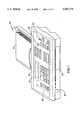
- FIG. 1 is a top perspective view of a facsimile machine incorporating a presently preferred embodiment of the invention
- FIG. 2 is a back perspective view of the machine of FIG. 1 with its upper automatic document guide in open position exposing the document path past a scanning station;
- FIG. 3 is a presently preferred stripper or pick roller
- FIGS. 4 and 5 are side view illustrating the dynamic action of the pick roller of FIG. 3 and a presently preferred separator assembly which together enable individual document sheets to be picked one by one from a stack;
- FIG. 6 is a side cut-away view of the scanner unit of the facsimile machine of FIG. 1;
- FIG. 7 is a partial isometric view of a chassis portion of an upper guide member in closed position on a frame
- FIG. 8 is an enlarged fragmentary view of FIG. 7 looking up at the latching mechanism and certain reference datums;
- FIG. 9 is a complete side view of FIG. 7; of FIG. 10 is a side view of the frame portion of FIG. 7 showing the transfer gears from a motor to the pick roller, pre-scanning primary drive roller and post-scanning (kickout) secondary drive roller;
- FIG. 11 is a side view of a chassis mounted on an upper guide member having a control/display member
- FIG. 12 is a side view of only the chassis portion of FIG. 11;
- FIG. 13 is an enlarged fragmentary view of FIG. 12 showing a spring-biased limiter
- FIG. 14 is a bottom view looking up at a portion of FIG. 11;
- FIG. 15 is a top view of only the chassis portion of FIG. 11, with the separator assembly mounted thereon, and showing the spring-biased mounting of the pre-scanning and post-scanning pinch rollers.
- the invention includes a scanning unit such as a facsimile machine, an automatic document feeder transports individual sheets from a stack of documents along a document path over a scanning window to an output tray.
- An upper guide member includes an integrated rigid chassis for positioning document control components adjacent the scanning window.
- the document control components included a central pre-scanning pinch roller, a full width hold-down limiter, and a central post-scanning pinch roller which are each mounted with their own separate biasing springs on the integrated chassis.
- Two elongated wire springs respectively engage both ends of the hold-down limiter, while two sets of cantilever leaf springs provide strong and weak spring biasing, respectively, to the pre-scanning and post-scanning pinch rollers.
- FIG. 1 is a front perspective view of a facsimile machine 10 incorporating the preferred embodiment paper separator mechanism.
- Facsimile, machine 10 contains a paper tray 12 which slopes downward so that a paper stack 14 placed into tray 12 is urged toward the receiving portion of machine 10 by gravity. The paper stack 14 enters a slot in the back of machine 10.
- a paper separation mechanism within machine 10 pulls one sheet of paper at a time from the bottom of the stack 14 so that printing on the sheet may be read and subsequently transmitted by the facsimile machine 10 in a well known manner.
- the sheet may also be copied by machine 10.
- machine 10 is a printer which feeds in blank sheets of paper for printing thereon. The individual sheets of paper are then outputted through exit slot 16.
- a printing mechanism (not shown) is also provided in the complete machine 10 for printing received facsimile transmissions.
- the printing mechanism which may be an inkjet or laser printer, can also be used when machine 10 is used as a copier or printer.
- FIG. 2 is a back perspective view of the facsimile machine 10 with its hinged top portion 17 lifted up to reveal the paper separation and paper transport mechanisms. Paper feed tray 12 has been removed in FIG. 2 for simplicity.
- top portion 17 is in its closed position, shown in FIG. 1, and paper stack 14 is placed in paper tray 12, the front edge of the stack extending over shelf 18 abuts against a rubber stripper roller 20, and paper-feed springs 22 and 24 provide a downward force on paper stack 14.
- a rubber separator pad 26, biased downward. by a separator spring 27 effectively blocks all sheets but the bottom sheet so that only the bottom sheet directly contacted by the rubber stripper roller 20 is forwarded past separator pad 26.
- the average forwarding speed of stripper roller 20 is about 12 mm/sec.
- a downstream, rubber main feed roller 30 is rotated so as to have a faster paper forwarding speed (e.g., 26 mm/sec.) than stripper roller 20.
- a faster paper forwarding speed e.g., 26 mm/sec.
- stripper roller 20 is driven via a slip clutch, which allows stripper roller 20 to rotate at the increased forwarding speed of main feed roller 30 when a single sheet of paper simultaneously contacts both rollers 20 and 30.
- Main feed roller 30 forwards the paper over a window 34, below which resides the necessary optical detection electronics for detecting the printing on the bottom sheet.
- Such optical electronics can be conventional and will not be described in detail herein. If machine 10 were solely a printer, window 34 and the optical electronics may be replaced by a printing mechanism.
- a kick-out roller 36 in conjunction with a passive opposing roller 38, has a 2% faster forwarding speed than main feed roller 30 to ensure that there is no slack in the paper between rollers 30 and 36.
- the pulling force of main feed roller 30 is approximately 3 pounds, while the pulling force of kick-out roller 36 is approximately 1.5 pounds, so the speed of the paper is controlled by main feed roller 30 rather than kick-out roller 36.
- a single stepper motor drives each of the rollers 20, 30, and 36, and gear mechanisms and slip clutch mechanisms are used for driving rollers 20, 30, and 36 at the required rotational speeds and forces.
- the below-described stripper roller 20 and opposing spring assembly (comprising springs 22,24, and 27 and separator pad 26) improve the separating function of the-stripper mechanism to compensate for the varying forces initially exerted on the paper stack 14 when the user inserts the stack 14 into machine 10.
- FIG. 3 is a perspective view of the preferred embodiment stripper roller 20.
- Stripper roller 20 includes eccentric kicker portions 40 and 42 located at the ends of the cylindrical middle portion 44 (also identified in FIG. 2).
- Stripper roller 20 is forcedly slipped over a stainless steel shaft 46 and is frictionally secured to shaft 46.
- Shaft 46 includes a flattened end 48 which is ultimately secured to a suitable slip clutch and gear mechanism within facsimile machine 10 for rotating stripper roller 20.
- a molded plastic shim 50 is attached to shaft 46 and includes an extension which is inserted under kicker portion 40 to create the eccentricity of kicker portion 40.
- An identical shim 51 is used to create the eccentricity of kicker portion 42.
- FIGS. 4 and 5 illustrate the operation of the accentric kicker portions 40 and 42 as the apex 60 makes a first revolution after a paper stack 14 is inserted into the facsimile machine 10.
- a user inserts a paper stack 14 in the direction shown by arrow 61 between paper-feed springs 22/24 and kicker portions 40/42 of roller 20.
- the user senses the resistance to further insertion of the paper stack 14 and releases the paper stack 14.
- the actual extent to which the payer stack 14 is inserted between roller 20 and paper-feed springs 22/24 thus varies depending upon the user.
- the downward force applied by paper-feed springs 22/24 is thus increased (causing the friction between the kicker portions 40/42 and the bottom paper sheet to be increased).
- the apex 60 of kicker portions 40/42 effectively reaches out to contact a greater bottom surface area of the bottom paper sheet so that the bottom sheet is pulled forward by the direct frictional contact with the kicker portions 40/42, while the other sheets are pulled forward with less force by their friction with this bottom sheet.
- the downward angle of paper-feed springs 22/24 causes the paper stack 14 to spread forward to resemble a staircase (FIG. 5 ), while the bottom sheet or bottom few sheets continue to be carried forward by the high friction between the kicker portions 40/42 and the bottom sheet.
- FIG. 5 illustrates the position of stack 14 after being carried forward during the first rotation of stripper roller 20 at the point where apex 60 has now completed its function and advanced the bottom sheet 64 or bottom few sheets to be in contact with the rubber separator pad 26.
- the friction between the bottom sheet 64 and the rotating roller 20 continues to push the bottom sheet 64 out from under separator pad 26, while the sheets overlying this bottom sheet 64 are held back by contact with separator pad 26 and slip with respect to the bottom sheet 64.
- the main feed roller 30 controls the forwarding of the bottom sheet, as previously described with respect to FIG. 2.
- top portion 17 generally constitutes an upper guide member which is held in a closed position during scanning by a pair of upstanding spring latches 70/71.
- the various document control components previously described including a composite separator assembly 72, and the passive rollers 32/38 are mounted in a rigid chassis 74 preferably made of sheet metal. Also directly mounted on the chassis are electrostatic discharge devices (ESD) such as conductive brushes 76 located adjacent the document path exit 16.
- ESD electrostatic discharge devices
- the preferred embodiment provides a display window 78 on a display/control panel 80 which have respective circuit board components 82/84 shown by dotted lines which are sandwiched against the chassis 74.
- a ground plate (not shown) framing the display panel is directly grounded to the metallic chassis which also acts as a shield to protect the circuit board elements from damage by ESD.
- the chassis is grounded to the frame by a separate ground wire (not shown) and also through a metallic pivot hinge to be described hereinafter.
- FIG. 6 The details of the scanner are best shown in FIG. 6, including a LED illumination array 86, an opaque baffle 88, a transparent scanning window 90, and mirrors 91/92/93 which transfer the optical signals from a document being scanned through a lens 94 to a CCD array 100.
- a limiter 95 having level portion 96, angled portion 97, lever arms 98, and mounting tabs or fingers 99 is held loosely at its left and right ends by engagement of the tabs 99 with slots 74s (FIG. 7) formed in a generally flat, post-scanning segment of the chassis 74.
- the upper, forward end of the angled portion 97 of the limiter terminates in lever arms 98, whose forwardmost ends are bent back down, somewhat past the chassis plane, as best seen in FIG. 13.
- the limiter 95 is thereby spring biased to press a document somewhat tightly out of its normal position between the two drive rollers to a predetermined location in close proximity but preferably not touching the scanning window.
- the angled portion helps guide the document without obstructing the document path.
- a white background for calibration purposes is provided on bottom surfaces of the level and angled portions 96/97, such as Kimdura plasticized paper which is specialized optical material having suitable optical characteristics as well as suitable durability during normal use and cleaning.
- the limiter is spring loaded to exert a force of at least 1/10 of a pound (approximately 0.5 newtons) in order to overcome any counterbalancing from the document sheet. In reality, the actual spring force use is about five times that minimum amount to avoid the need for precise tolerances during manufacturing.
- FIGS. 7-9 show the details of the pivotal hinging, as well as the referencing and latching between the chassis of the upper guide member and the frame.
- the latch spring mechanism includes a base 102, a frame mounting pin 103, chassis lip 104, a V-shaped spring extension 105, and a chassis aperture 106.
- An upstanding ann 110 has a shoulder surface 111 which engages a Z-datum surface 112 on the chassis, edge 74e and also has a tapered tongue 113 with a Y-axis datum reference edge 114 to engage a Y-axis datum reference seat 115 on the chassis and a non-reference edge which preferably has a slight clearance relative to the reference seat.
- Both of the V-shaped spring extensions push outwardly, as well as downwardly to securely engage the reference surfaces.
- Each pivoting leg 120 on the chassis potentially abuts a downwardly facing secondary datum 121 as it moves between open and closed positions in a pivoting slot 122 (FIG. 6) in the frame.
- a wire spring 125 is suspended between two bridge elements 126, 127 formed in respective angled segments 74 a of the chasis, and passes through an aperture 128 in the lever arm 8 of the limiter, and around the end of the lever ann of the limiter to provide the aforementioned spring biasing (see FIGS. 7 and 13).
- FIGS. 10 shows the gear train going from a motor shaft 130 through first and second transfer gears 131/132 to pick roller gear 133, through first transfer gear 131 to pre-scanning roller gear 134, and through third transfer gear 135 to post-scanning roller gear 136.
- the holes for the gear shafts are respectively shown in FIG. 9.
- FIG. 11 shows the chassis mounted on the upper guide member which has a slotted guide 138 with a flex-ann to temporarily hold the upper guide member in open position and a stop 139 to prevent opening the upper guide member too far.
- FIG. 12 shows the same view of the chassis separate from the upper guide member.
- FIG. 14 shows the positioning of the separation assembly and the two idler rollers as well as the mounting screw hole 140 for the wire spring.
- Slots 142/143 are for a first sensor flag to detect documents inserted for scanning, and a second sensor flag to detect a single document sheet which has already been picked and is headed for the scanning window.
- FIG. 15 shows one cantilever leaf spring 150 (its mate is not shown) mounted on a first hole 151 to provide a short cantilever arm 152, and a second identical cantilever leaf spring 154 (its mate is not shown) mounted on a second hole 155 to provide a longer cantilever arm 156.
- Each idler roller is a hollow hard plastic roller which is mounted on a stationary axle 158 held in lengthwise position by flange brackets 160 and held in Z-axis position by small holes 162 in each of the cantilever leaf springs.
- the cantilever leaf springs also include a positioning flange for mounting on their upstanding brackets 164.
Landscapes
- Sheets, Magazines, And Separation Thereof (AREA)
- Facsimiles In General (AREA)
- Delivering By Means Of Belts And Rollers (AREA)
- Paper Feeding For Electrophotography (AREA)
Abstract
Description
              TABLE I
______________________________________
        diameter
               hardness doc. speed spr. force
______________________________________
PickRoller
            19 mm  30       12.7 mm/sec
                                     N/A
                   shoreA
PreScanRoller
          12.7 mm  50       25.9 mm/sec
                                     2 × 1.6 lbs
                   shoreA
PostScanRoller
          12.9 mm  50       26.3 mm/sec
                                     2 × 1.8 lbs
                   shoreA
______________________________________
Claims (21)
Priority Applications (4)
| Application Number | Priority Date | Filing Date | Title |
|---|---|---|---|
| US08/324,821 US5547179A (en) | 1994-10-17 | 1994-10-17 | Scanning unit with independent spring-loaded document control components mounted on an integrated chassis |
| JP24451395A JP3648295B2 (en) | 1994-10-17 | 1995-09-22 | Scanning unit with independent spring-loaded document control elements attached to an integrated chassis |
| DE69517281T DE69517281T2 (en) | 1994-10-17 | 1995-10-16 | Scanning unit with independent spring loaded document regulators which are mounted on an integrated frame |
| EP95116308A EP0707974B1 (en) | 1994-10-17 | 1995-10-16 | Scanning unit with independent spring-loaded document control components mounted on an integrated chassis |
Applications Claiming Priority (1)
| Application Number | Priority Date | Filing Date | Title |
|---|---|---|---|
| US08/324,821 US5547179A (en) | 1994-10-17 | 1994-10-17 | Scanning unit with independent spring-loaded document control components mounted on an integrated chassis |
Publications (1)
| Publication Number | Publication Date |
|---|---|
| US5547179A true US5547179A (en) | 1996-08-20 |
Family
ID=23265244
Family Applications (1)
| Application Number | Title | Priority Date | Filing Date |
|---|---|---|---|
| US08/324,821 Expired - Lifetime US5547179A (en) | 1994-10-17 | 1994-10-17 | Scanning unit with independent spring-loaded document control components mounted on an integrated chassis |
Country Status (4)
| Country | Link |
|---|---|
| US (1) | US5547179A (en) |
| EP (1) | EP0707974B1 (en) |
| JP (1) | JP3648295B2 (en) |
| DE (1) | DE69517281T2 (en) |
Cited By (12)
| Publication number | Priority date | Publication date | Assignee | Title |
|---|---|---|---|---|
| US5923436A (en) * | 1996-03-13 | 1999-07-13 | Mita Industrial Co., Ltd. | Facsimile machine |
| US6203005B1 (en) | 1999-03-04 | 2001-03-20 | Bell & Howell Company | Feeder apparatus for documents and the like |
| US6305684B1 (en) | 1999-03-04 | 2001-10-23 | Werner R. Lightner | Feed rollers with reversing clutch |
| US6457707B1 (en) | 2000-11-22 | 2002-10-01 | Hewlett-Packard Co. | Automatic document feeder |
| US20030038988A1 (en) * | 2001-08-24 | 2003-02-27 | Anderson Bradley J. | Dual scanner system and method |
| US6578845B2 (en) * | 2001-04-09 | 2003-06-17 | Mustek Systems Inc. | Automatic document feeding apparatus having separation mechanism |
| US6585252B1 (en) | 2000-03-02 | 2003-07-01 | Jim T. Russo | Semi-active clutch assembly |
| US6688590B2 (en) | 2000-12-08 | 2004-02-10 | Lexmark International, Inc. | Dual tray printer with single drive shaft and dual media picks |
| US6837635B1 (en) * | 1999-03-08 | 2005-01-04 | Hewlett-Packard Development Company, L.P. | Inkjet apparatus and method for controlling undulation on media |
| US20100059925A1 (en) * | 2008-09-08 | 2010-03-11 | Kabushiki Kaisha Toshiba | Image forming apparatus |
| US9065947B2 (en) | 2013-08-30 | 2015-06-23 | Brother Kogyo Kabushiki Kaisha | Image reading apparatus |
| CN104925552A (en) * | 2014-03-19 | 2015-09-23 | 佳能株式会社 | Sheet conveying apparatus and image forming apparatus |
Citations (6)
| Publication number | Priority date | Publication date | Assignee | Title |
|---|---|---|---|---|
| US3430947A (en) * | 1967-03-20 | 1969-03-04 | Burroughs Corp | Record card handling and registering apparatus |
| US4508444A (en) * | 1982-08-02 | 1985-04-02 | Xerox Corporation | Multimode document handling apparatus and reproducing apparatus containing same |
| JPS63272734A (en) * | 1987-04-30 | 1988-11-10 | Tokyo Electric Co Ltd | Holding device for pinch roller |
| JPS6433847A (en) * | 1987-07-30 | 1989-02-03 | Toshiba Corp | Halogen electric lamp |
| JPS6450651A (en) * | 1987-08-21 | 1989-02-27 | Canon Kk | Mixed mode terminal equipment |
| JPH0213533A (en) * | 1988-06-30 | 1990-01-17 | Toshiba Corp | Conveyance roller of paper feed device |
Family Cites Families (2)
| Publication number | Priority date | Publication date | Assignee | Title |
|---|---|---|---|---|
| US3661383A (en) * | 1970-01-22 | 1972-05-09 | Pitney Bowes Inc | Document handling apparatus for photocopy machines |
| JP2992941B2 (en) * | 1992-06-16 | 1999-12-20 | 三田工業株式会社 | Automatic document feeder |
-
1994
- 1994-10-17 US US08/324,821 patent/US5547179A/en not_active Expired - Lifetime
-
1995
- 1995-09-22 JP JP24451395A patent/JP3648295B2/en not_active Expired - Fee Related
- 1995-10-16 DE DE69517281T patent/DE69517281T2/en not_active Expired - Fee Related
- 1995-10-16 EP EP95116308A patent/EP0707974B1/en not_active Expired - Lifetime
Patent Citations (6)
| Publication number | Priority date | Publication date | Assignee | Title |
|---|---|---|---|---|
| US3430947A (en) * | 1967-03-20 | 1969-03-04 | Burroughs Corp | Record card handling and registering apparatus |
| US4508444A (en) * | 1982-08-02 | 1985-04-02 | Xerox Corporation | Multimode document handling apparatus and reproducing apparatus containing same |
| JPS63272734A (en) * | 1987-04-30 | 1988-11-10 | Tokyo Electric Co Ltd | Holding device for pinch roller |
| JPS6433847A (en) * | 1987-07-30 | 1989-02-03 | Toshiba Corp | Halogen electric lamp |
| JPS6450651A (en) * | 1987-08-21 | 1989-02-27 | Canon Kk | Mixed mode terminal equipment |
| JPH0213533A (en) * | 1988-06-30 | 1990-01-17 | Toshiba Corp | Conveyance roller of paper feed device |
Cited By (15)
| Publication number | Priority date | Publication date | Assignee | Title |
|---|---|---|---|---|
| US5923436A (en) * | 1996-03-13 | 1999-07-13 | Mita Industrial Co., Ltd. | Facsimile machine |
| US6203005B1 (en) | 1999-03-04 | 2001-03-20 | Bell & Howell Company | Feeder apparatus for documents and the like |
| US6305684B1 (en) | 1999-03-04 | 2001-10-23 | Werner R. Lightner | Feed rollers with reversing clutch |
| US6837635B1 (en) * | 1999-03-08 | 2005-01-04 | Hewlett-Packard Development Company, L.P. | Inkjet apparatus and method for controlling undulation on media |
| US6585252B1 (en) | 2000-03-02 | 2003-07-01 | Jim T. Russo | Semi-active clutch assembly |
| US6457707B1 (en) | 2000-11-22 | 2002-10-01 | Hewlett-Packard Co. | Automatic document feeder |
| US6688590B2 (en) | 2000-12-08 | 2004-02-10 | Lexmark International, Inc. | Dual tray printer with single drive shaft and dual media picks |
| US6578845B2 (en) * | 2001-04-09 | 2003-06-17 | Mustek Systems Inc. | Automatic document feeding apparatus having separation mechanism |
| US20030038988A1 (en) * | 2001-08-24 | 2003-02-27 | Anderson Bradley J. | Dual scanner system and method |
| US6856423B2 (en) | 2001-08-24 | 2005-02-15 | Hewlett-Packard Development Company, L.P. | Dual scanner system and method |
| US20100059925A1 (en) * | 2008-09-08 | 2010-03-11 | Kabushiki Kaisha Toshiba | Image forming apparatus |
| US8196917B2 (en) * | 2008-09-08 | 2012-06-12 | Kabushiki Kaisha Toshiba | Detachable feed member with detection unit |
| US9065947B2 (en) | 2013-08-30 | 2015-06-23 | Brother Kogyo Kabushiki Kaisha | Image reading apparatus |
| CN104925552A (en) * | 2014-03-19 | 2015-09-23 | 佳能株式会社 | Sheet conveying apparatus and image forming apparatus |
| CN104925552B (en) * | 2014-03-19 | 2017-04-12 | 佳能株式会社 | Sheet conveying apparatus and image forming apparatus |
Also Published As
| Publication number | Publication date |
|---|---|
| JPH08204897A (en) | 1996-08-09 |
| DE69517281D1 (en) | 2000-07-06 |
| EP0707974B1 (en) | 2000-05-31 |
| JP3648295B2 (en) | 2005-05-18 |
| DE69517281T2 (en) | 2000-12-28 |
| EP0707974A2 (en) | 1996-04-24 |
| EP0707974A3 (en) | 1998-03-04 |
Similar Documents
| Publication | Publication Date | Title |
|---|---|---|
| US6151140A (en) | Integrated chassis for automatic document feeder in a scanning unit | |
| US5547179A (en) | Scanning unit with independent spring-loaded document control components mounted on an integrated chassis | |
| US6659450B2 (en) | Sheet feeding apparatus and automatic document using the same | |
| EP0591543A1 (en) | Image reader | |
| JP2004032152A (en) | Automatic document feeder | |
| EP0511004A2 (en) | Original image reading device and image information processing apparatus having the same | |
| US5553842A (en) | Precision referencing/latching system for document separation and transport in a scanning unit | |
| US7753363B2 (en) | Paper feeding device | |
| US6565079B1 (en) | Document feeder, document feed method, and image capture device | |
| EP0706895B1 (en) | Asymmetrical paper separator roller for facsimile or copy machine | |
| US5537227A (en) | Paper picking and separator system for facsmile or copy machine | |
| JP3378123B2 (en) | Document separation and transport device | |
| JP4332696B2 (en) | Paper feeder | |
| JP3231497B2 (en) | Reader and facsimile apparatus using the same | |
| US7686526B2 (en) | Document feeder device | |
| JP3446395B2 (en) | Automatic document separation and transport device | |
| JP3626944B2 (en) | Automatic document feeder | |
| JP4266475B2 (en) | Image reading device | |
| JP3846894B2 (en) | Document conveying device and document reading device | |
| KR100272293B1 (en) | Apparatus for scanning paper of facsimile | |
| KR0181801B1 (en) | Cis combining apparatus for facsimile | |
| JPH11187193A (en) | Image reading device | |
| JPH04333437A (en) | Document feeding device | |
| JPH0351249A (en) | Paper feed device | |
| JPS63220656A (en) | Manual scanning type reader |
Legal Events
| Date | Code | Title | Description |
|---|---|---|---|
| AS | Assignment |
Owner name: E. I. DU PONT DE NEMOURS AND COMPANY, DELAWARE Free format text: ASSIGNMENT OF ASSIGNORS INTEREST;ASSIGNORS:HORTON, GARY L.;LARSON, JOHN C.;REEL/FRAME:007374/0051;SIGNING DATES FROM 19950130 TO 19950131 |
|
| STCF | Information on status: patent grant |
Free format text: PATENTED CASE |
|
| FEPP | Fee payment procedure |
Free format text: PAYOR NUMBER ASSIGNED (ORIGINAL EVENT CODE: ASPN); ENTITY STATUS OF PATENT OWNER: LARGE ENTITY |
|
| FPAY | Fee payment |
Year of fee payment: 4 |
|
| AS | Assignment |
Owner name: HEWLETT-PACKARD COMPANY, COLORADO Free format text: MERGER;ASSIGNOR:HEWLETT-PACKARD COMPANY;REEL/FRAME:011523/0469 Effective date: 19980520 |
|
| FPAY | Fee payment |
Year of fee payment: 8 |
|
| FPAY | Fee payment |
Year of fee payment: 12 |
|
| REMI | Maintenance fee reminder mailed | ||
| AS | Assignment |
Owner name: HEWLETT-PACKARD DEVELOPMENT COMPANY, L.P., TEXAS Free format text: ASSIGNMENT OF ASSIGNORS INTEREST;ASSIGNOR:HEWLETT-PACKARD COMPANY;REEL/FRAME:026945/0699 Effective date: 20030131 |