US553553A - a i jhjn i - Google Patents
a i jhjn i Download PDFInfo
- Publication number
- US553553A US553553A US553553DA US553553A US 553553 A US553553 A US 553553A US 553553D A US553553D A US 553553DA US 553553 A US553553 A US 553553A
- Authority
- US
- United States
- Prior art keywords
- valve
- piston
- lubricant
- cover
- receptacle
- Prior art date
- Legal status (The legal status is an assumption and is not a legal conclusion. Google has not performed a legal analysis and makes no representation as to the accuracy of the status listed.)
- Expired - Lifetime
Links
- 239000000314 lubricant Substances 0.000 description 18
- 239000012530 fluid Substances 0.000 description 12
- 230000001050 lubricating Effects 0.000 description 8
- 239000002184 metal Substances 0.000 description 4
- 229910001369 Brass Inorganic materials 0.000 description 2
- 229910001361 White metal Inorganic materials 0.000 description 2
- 239000010951 brass Substances 0.000 description 2
- 210000000038 chest Anatomy 0.000 description 2
- 230000000875 corresponding Effects 0.000 description 2
- 230000036633 rest Effects 0.000 description 2
- 238000005476 soldering Methods 0.000 description 2
- 239000010969 white metal Substances 0.000 description 2
Images
Classifications
-
- B—PERFORMING OPERATIONS; TRANSPORTING
- B61—RAILWAYS
- B61F—RAIL VEHICLE SUSPENSIONS, e.g. UNDERFRAMES, BOGIES OR ARRANGEMENTS OF WHEEL AXLES; RAIL VEHICLES FOR USE ON TRACKS OF DIFFERENT WIDTH; PREVENTING DERAILING OF RAIL VEHICLES; WHEEL GUARDS, OBSTRUCTION REMOVERS OR THE LIKE FOR RAIL VEHICLES
- B61F17/00—Lubrication specially adapted for axle-boxes of rail vehicles
- B61F17/30—Lubrication specially adapted for axle-boxes of rail vehicles with grease
- B61F17/34—Lubrication specially adapted for axle-boxes of rail vehicles with grease by automatic means, e.g. with spring action
Definitions
- the object of this invention is to provide efficient means for automatically lubricating the working surfaces of slide-valves used in hydraulic and other motive fluid engines.
- the valve is provided with one, or more lubricant rcceptacles in communication with the surface to be lubricated and provided, or each provided, with a piston arranged to be acted upon by the fluid under pressure within the valve chest in which the valve is to work, the arrangement being such that the piston, or each piston, will, in consequence of the pressure thereon, cause lubricant to flow from the receptacle to the surface to be lubricated.
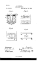
- Figures 1, 2, and 3 are respectively a cross-section, a plan, and an under-side view showing, by way of example, a hydraulic valve provided with means according to this invention for lubricating its working surface, and consequently also the surface upon which it works.
- Figs. 4 and 5 are elevations at right angles to each other showing a tool hereinafter more particularly referred to.
- chambers 2 which are adapted to serve as receptacles for lubricant and which communicate with the rubbing-surface 3 of the valve through ducts/i, which at their upper ends open into the bottoms of the chambers 2 through raised parts 5 and at their lower ends communicate with distributing grooves 4 formed in the said rubbing-surface 3.
- Each is made cylindrical and is provided with a well-fitting piston G, of any suitable materialfor example, leadarranged to work therein.
- Each piston when at the bottom of its stroke rests by its central portion upon the raised part 5 at the bottom of the cylinder, whereby the periphery of the piston, especially when of soft metal, such as lead, is prevented from being damaged by pressure against the bottom of the chamber.
- the chambers 2 are provided with covers 7 7 and pistons 6 are removed by means of a suitable tool inserted through holes (normally closed by plugs or equivalent means) provided for the purpose in the cover of the valve-chest, the tool being adapted to suitably engage with the said covers and pistons.
- a suitable tool inserted through holes (normally closed by plugs or equivalent means) provided for the purpose in the cover of the valve-chest, the tool being adapted to suitably engage with the said covers and pistons.
- the hole 8 in each cover may be provided with a left-handed screw-thread to receive a corresponding screw-thread on one end, 9, of a rod 9, Figs. 4 and 5, the other end, 9", of which may be formed as a screwdriver to enter a notch 7 n in the top of the cover '7.
- Each piston 6 may be provided with a similar screw-threaded hole 6 to permit of its being inserted in place and removed by a tool of the kind referred to.
- the piston is of a soft metal, such as lead or white metal, which I consider advantageous, the said screwthreaded hole may be formed in a brass socketpiece 6 suitably secured to the top of the piston, as by soldering.
- the terminal-ducts 4 of the rows of ducts on opposite sides of the valve are, or maybe, connected at that end of the valve which does not cross the ports to be controlled by a groove 4 made in the under side of the valve.
- lubricant chambers 2 with pistons 6, as hereinbefore de scribed can be varied to suit circumstances. Thus in some cases there maybe less or more than the number shown, according to the size and type of valve with which they are used.
- a valve provided with a lubricant receptacle having a perforated removable cover, and connected by a duct with the working face of the valve, and a piston adapted to work in said receptacle and arranged to be acted upon by fluid under pressure admitted through said cover, substantially as described.
- a valve having a number of lubricant receptacles 2 formed in the body thereof and also ducts 4 connecting said receptacles with its working face, pistons 6 arranged to work in said chambers, and removable perforated covers 7 screwed into the top of said receptacles, substantially as herein described for the purpose specified.
Description
. (No Model.)
J GURRAN LUBRIGATING VALVE.
Patented Jan. 28, 1896.
Fzlgti.
inventor.
Witnesses. I (wfiajmlk JAMES CURRAN, OF LONDON, ENGLAND.
LUBRICATING VALVES. i
SPECIFICATION forming part of Letters Patent N 0. 553,553, dated January 28, 1896:
ATENT OFFICE.
Application filed May 16, 1895. Serial No. 549,544. (No model.)
To all whom it may concern.-
Be it known that I, JAMES CURRAN, a subject of the Queen of Great Britain and Ireland,
' residing at Spa Road, Bermondsey, London,
chamber 2 in the county of London, England, have invented Improvements in Lubricating Valves, of which the following is a specification.
The object of this invention is to provide efficient means for automatically lubricating the working surfaces of slide-valves used in hydraulic and other motive fluid engines. For this purpose the valve is provided with one, or more lubricant rcceptacles in communication with the surface to be lubricated and provided, or each provided, with a piston arranged to be acted upon by the fluid under pressure within the valve chest in which the valve is to work, the arrangement being such that the piston, or each piston, will, in consequence of the pressure thereon, cause lubricant to flow from the receptacle to the surface to be lubricated.
In theaccompanying drawings, Figures 1, 2, and 3 are respectively a cross-section, a plan, and an under-side view showing, by way of example, a hydraulic valve provided with means according to this invention for lubricating its working surface, and consequently also the surface upon which it works. Figs. 4 and 5 are elevations at right angles to each other showing a tool hereinafter more particularly referred to.
In the body 1 of the valve there are formed chambers 2, which are adapted to serve as receptacles for lubricant and which communicate with the rubbing-surface 3 of the valve through ducts/i, which at their upper ends open into the bottoms of the chambers 2 through raised parts 5 and at their lower ends communicate with distributing grooves 4 formed in the said rubbing-surface 3. Each is made cylindrical and is provided with a well-fitting piston G, of any suitable materialfor example, leadarranged to work therein. Each piston when at the bottom of its stroke rests by its central portion upon the raised part 5 at the bottom of the cylinder, whereby the periphery of the piston, especially when of soft metal, such as lead, is prevented from being damaged by pressure against the bottom of the chamber. The chambers 2 are provided with covers 7 7 and pistons 6 are removed by means of a suitable tool inserted through holes (normally closed by plugs or equivalent means) provided for the purpose in the cover of the valve-chest, the tool being adapted to suitably engage with the said covers and pistons. For this purpose, assuming the screw-thread on the periphery of each cover to be righthanded, the hole 8 in each cover may be provided with a left-handed screw-thread to receive a corresponding screw-thread on one end, 9, of a rod 9, Figs. 4 and 5, the other end, 9", of which may be formed as a screwdriver to enter a notch 7 n in the top of the cover '7. WVith this arrangement, assuming the covers to be in place, it will be seen that by screwing the rod 9 tightly into the hole 8 of each cover in turn and continuing to turn the rod after it has been fully screwed in the cover can be unscrewed from the body of the valve and removed, and that the cover can be afterward returned by and partly screwed into place by the rod, the end 9 of which may be used to complete the screwing up, if necessary.
Each piston 6 may be provided with a similar screw-threaded hole 6 to permit of its being inserted in place and removed by a tool of the kind referred to. When the piston is of a soft metal, such as lead or white metal, which I consider advantageous, the said screwthreaded hole may be formed in a brass socketpiece 6 suitably secured to the top of the piston, as by soldering.
The terminal-ducts 4 of the rows of ducts on opposite sides of the valve are, or maybe, connected at that end of the valve which does not cross the ports to be controlled by a groove 4 made in the under side of the valve. The
is removed from the valve-chest, and to contract the outer ends of the lubricant-chambers and prevent ready access of dirt thereto.
As will be obvious, the number of lubricant chambers 2 with pistons 6, as hereinbefore de scribed, can be varied to suit circumstances. Thus in some cases there maybe less or more than the number shown, according to the size and type of valve with which they are used.
It will be understood that the feeding of the lubricant from the chamber or chambers 2 will cease automatically when the supply of motive fluid is out off from the valve-chest in which the valve works.
What I claim isl. The combination, in a prime mover "alve, of a receptacle for lubricant, a piston adapted to work in the said receptacle and arranged to be acted upon in the valve-chest by the motive fluid contained therein, and a duct forming a communication between the said receptacle and the surface of the valve to be lubricated, substantially as set forth.
2'. A valve provided with a lubricant receptacle having a perforated removable cover, and connected by a duct with the working face of the valve, and a piston adapted to work in said receptacle and arranged to be acted upon by fluid under pressure admitted through said cover, substantially as described.
3. The combination with a slide valve of lubricators each consisting of a lubricant receptacle connected by a duct with the working face of the valve and provided with a piston adapted to work therein arranged to be acted upon by fluid under pressure and provided with an internally screw-threaded hole, and a perforated cover screwed into one end of the said receptacle and provided with a screwthreaded hole, substantially as herein described for the purposes specified.
4. A valve having a number of lubricant receptacles 2 formed in the body thereof and also ducts 4 connecting said receptacles with its working face, pistons 6 arranged to work in said chambers, and removable perforated covers 7 screwed into the top of said receptacles, substantially as herein described for the purpose specified.
In testimony whereof I have signed my name to this specification in the presence of two subscribing Witnesses.
JAMES CURRAN.
\Vitnesses:
M. A. V. LONDON, HUGH HUGHES.
Publications (1)
| Publication Number | Publication Date |
|---|---|
| US553553A true US553553A (en) | 1896-01-28 |
Family
ID=2622293
Family Applications (1)
| Application Number | Title | Priority Date | Filing Date |
|---|---|---|---|
| US553553D Expired - Lifetime US553553A (en) | a i jhjn i |
Country Status (1)
| Country | Link |
|---|---|
| US (1) | US553553A (en) |
Cited By (1)
| Publication number | Priority date | Publication date | Assignee | Title |
|---|---|---|---|---|
| EP1689959B2 (en) † | 2003-11-14 | 2010-11-03 | Integración De Montajes Y Plásticos, S.L. | Inside door element for a motor vehicle comprising a cover used as a break-in prevention device |
-
0
- US US553553D patent/US553553A/en not_active Expired - Lifetime
Cited By (1)
| Publication number | Priority date | Publication date | Assignee | Title |
|---|---|---|---|---|
| EP1689959B2 (en) † | 2003-11-14 | 2010-11-03 | Integración De Montajes Y Plásticos, S.L. | Inside door element for a motor vehicle comprising a cover used as a break-in prevention device |
Similar Documents
| Publication | Publication Date | Title |
|---|---|---|
| US553553A (en) | a i jhjn i | |
| US143216A (en) | Improvement in oil-cups | |
| US987962A (en) | Pump. | |
| US690510A (en) | Lubricator for steam-engine pistons. | |
| US136136A (en) | Improvement in valve- lubricators | |
| US234864A (en) | Lubricating-pump | |
| US1017415A (en) | Automatic choke-valve. | |
| US587272A (en) | Oiling device | |
| US667148A (en) | Lubricator. | |
| US1536010A (en) | Lubricator | |
| US165756A (en) | Improvement in lubricators | |
| US730813A (en) | Lubricating device. | |
| US214730A (en) | Improvement in lubricators | |
| US1026526A (en) | Steam-engine lubricator. | |
| US139286A (en) | Improvement in lubricator | |
| US849495A (en) | Lubricator for explosive-engines. | |
| US806167A (en) | Piston. | |
| US823349A (en) | Lubricator for engine-valves. | |
| US162160A (en) | Improvement in lubricators for steaivi-engifsses | |
| US354419A (en) | Ohables hiesch | |
| US1778396A (en) | Water-pump lubricator | |
| GB484239A (en) | Improvements relating to valves for controlling fluids | |
| US305887A (en) | Steam-engine lubricator | |
| US2596963A (en) | Lubricated plug valve | |
| US779661A (en) | Gravity-valve. |