US553189A - foeste - Google Patents
foeste Download PDFInfo
- Publication number
- US553189A US553189A US553189DA US553189A US 553189 A US553189 A US 553189A US 553189D A US553189D A US 553189DA US 553189 A US553189 A US 553189A
- Authority
- US
- United States
- Prior art keywords
- lever
- spindle
- levers
- ruling
- cylinder
- Prior art date
- Legal status (The legal status is an assumption and is not a legal conclusion. Google has not performed a legal analysis and makes no representation as to the accuracy of the status listed.)
- Expired - Lifetime
Links
- 241000282472 Canis lupus familiaris Species 0.000 description 13
- 238000004040 coloring Methods 0.000 description 9
- 230000001105 regulatory effect Effects 0.000 description 4
- 238000010276 construction Methods 0.000 description 2
- 230000002093 peripheral effect Effects 0.000 description 2
- 238000004519 manufacturing process Methods 0.000 description 1
- 230000002035 prolonged effect Effects 0.000 description 1
Images


Classifications
-
- B—PERFORMING OPERATIONS; TRANSPORTING
- B41—PRINTING; LINING MACHINES; TYPEWRITERS; STAMPS
- B41G—APPARATUS FOR BRONZE PRINTING, LINE PRINTING, OR FOR BORDERING OR EDGING SHEETS OR LIKE ARTICLES; AUXILIARY FOR PERFORATING IN CONJUNCTION WITH PRINTING
- B41G3/00—Apparatus for printing lines
Definitions
- the present invention consists of an improved rulingmachine, and the improvements comprise, first, the arrangement of the ruling-disks by which when the same are raised from the paperthey are simultaneously brought out of contact with the coloring-roll; second, novel means for raising the rulingdisks to interrupt the lines at will; third, the arrangement of the conveyer--apron with regard to the threads, by means of which the tension of the said apron is regulated independently of the threads, whereby crumpling of the sheets is avoided.
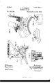
- Figure 1 is a side elevation of the Inachine Fig. 2, a plan, partly in section.
- Fig. 3 is a perspective view showing the device for raising the ruling-disks.
- Fig. 4 shows in detail the eccentric attachment for the shaft of the ruling-disks.
- Fig. 5 is a detail view of the roller-disk-shaft bearing and mechanism for lifting the same.
- Fig. 6 shows a detail view of the mechanism for actuating the liftingshaft.
- Fig. 7 is a detail section of the eccentric trunnion whereon the bearings of the ruling-disk shaft are mounted;
- Fig. 8 a partside elevation of the dogs for actuating the lifting mechanism, and
- Fig. 9 an end elevation of Fig. 8.
- Fig. 1 shows the general construction ofthe machine, but especially the arrangement of the inking devices around the cylinder and the course of the endless apron.
- Figs. 4 to 9 represent details of construction on a large scale.
- the ruler-axle is held in a pair of bearings g', arranged on the right and left side of themachine, each bearing being adapted to oscillate on a stud E.
- Fig. 5 the ruler-axle is held in a pair of bearings g', arranged on the right and left side of themachine, each bearing being adapted to oscillate on a stud E.
- the bearing of this stud is eccentric to the ink-roller zr, so that on the bearing g beinglifted by means of the lever or cam 7L mounted on shaft s the ruling-disks g/ are placed out of contact with the ink-roller .n
- This eccentric position has the advantage that in the raised condition of the bearing g', and if the machine continues to turn, as is necessary for the production of broken lines, closely-ruled lines (as used for the heading of papers) will not fiow into each other.
- Fig. 6 For interrupting the lines at will, I employ the mechanism illustrated by Fig. 6, which is situated at the end of the shaft s' and only on one side of the Inachine.
- lever 7c3 which is rigidly connected with the shaft s', there is mounted on the said shaft s' an adjustable eccentric sleeve o'.
- This sleeve carries another sleeve o2, adapted to turn thereon, and provided with two arms l', which carry the fulcrum or axle t2 of lthe liftingroller r2.
- One of the said arms l has a fiattened extremity or a plate Z2 and is pressed against a set-screw q, fixed in the lever 7a3, by means of a helical spring 7.24.
- each inkin g apparatus may come into contact with all the lifting-dogs a3 of a groove, or each roller r2 may be set in motion independently of the other by the liftingdogs u2 of the'iirst or the second or the third groove only.
- the said dogs us are supplied in various lengths and may be used in pairs in each groove of the drum t and at any desired part of each groove, they may serve to produce a great variety of broken lines. After one of the said dogs a3 has been t placed at the desired part of the groove or circumference, it is secured in position by means of a wedge e, provided with a screw w, as shown by Fig. 9.
- the cam Zt' may be adj usted accurately with regard to the lever g by means of a flat spring i, attached at one end under the said lever g and bearing against the said cam, said spring t" having its free end adjustable by means of a set-screw f in the lever g.
- Fig. 3 shows the relative position and arrangement of the parts described above on the cylinder.
- the mechanism for producing the blanks consisting of levers k2 Z2, eccentric sleeve 0/, lifting-roller r2, grooved drum c, and lifting-dogs u2, exist on one side only of the machine, while the ruleraXle bearing g', together with its mechanism, as well as the lever h, are arranged for each inking apparatus in duplicate-that is to say, on each side of the machine.
- the dog u2 has inclined faces, and is held in the groove by means of a Wedge z which is pressed against an inclined extension u2 of the dog u2 by turning the screw w. If the screw is loosened, the dog u and key z may be lifted out of the groove together, being only held therein by friction.
- FIG. l G designates the endless apron; H, the upper threads; J, the lower threads; L', the iirst inking apparatus; L2 the second, and L3 the third inking apparatus; M the cylinder, and K the delivery-table.
- the upper and lower threads are taken over different rolls quite independent of those employed to guide the endless apron.
- the threads I-I and J pass from between the rolls 1 and 2 around roll 6, cylinder M, rolls 7, 11, 13, and separate again at roll lei, the lower thread, J, passing rolls 14, 15, and 12 to roll 2, the upper thread being taken over rolls 16, 17, and 1S to roll 1.
- the apron passes around different rolls coming from roll 2 under 5, around the cylinder M, rolls 8 and 9, over 11, back under l2 and up to 2 again.
- the object of this arrangement is to keep the tension of the apron and threads equal with regard to each other. If apron and the threads are guided by the same set of rolls the apron gets creased,often creasing and crumpling the sheets of paper. This creasing or slackening of the apron is due to various causes, principally probably to the difference in the elasticity of the apron and threads and the friction exercised by both. I have found that the only way to obviate this disadvantage is to take the apron at times out of contact with the threads, as at 8 and 9, and again at 5, whereby both apron and threads run partially independent of each other.
- a ruling machine the combination of levers g', pivoted at the ends of the coloring cylinder but eccentrically as regards the same, and having downwardly extending arms, a ruling disk spindle mounted in said arms, and a spring to said levers adapted to hold same in a position to normally contact with the paper cylinder and the coloring cylinder but on being raised to leave the said coloring cylinder, and means for turning the said lever as specified.
- levers g g pivoted eccentrically with the coloring cylinder and carrying the ruling disk spindle a spindle s mounted underneath the said levers gf in the machine frame, a cam 71, fast on said spindle s, a sleeve fast on the outer end of said spindle carrying lever arms Z Z2, a laterally adjustable.
- roll r2 mounted between said lever arms, a disk u on the shaft of the paper cylinder and having thereon dogs to contact said roll and means to keep the cam h in contact with the lever g substantially as described.
- levers g g pivoted eccentrically with the coloring cylinder and carrying the ruling disk spindle a spindle s mounted underneath said levers g', in the machine frame, a cam h fast on said spindle, a sleeve fast on the outer end of said spindle carrying lever arms Zl Z2, a laterally adjustable roll fr?
Landscapes
- Making Paper Articles (AREA)
Description
(NdMoaeL) s' sheets-sheen 1.
C. I'. FRSTE. -RULING MACHINE.
No. 553,189. Patented-Jan. 14, 1896.
(N MOdeL) 3'Sheets-Sheet 2. C. F. FRSTE.
y RULING MAGHINL. No. 553,189. Patented Jan. 14, 1896.
u forneys (No Model.) V3 Sheets-Sheet 3. G. I'. FRSTE.
- RULING MACHINE.
No. 553,189. Patented Jan. 14, 1896.
AN DREW BLRAKAM FHOT0-LHIIO-WASHINGTDNB C.
UNITED STATES PATENT GEEICE.
cARI. FRIEDRICH EoRs'r J, or LEIPsIc, GERMANY, AssIGNoR 'ro rRsTE a- TRoMIII, oF sAIIE PLACE.
RULlNG-IVIACHINE.
SPECIFICATIONWforming part of Letters Patent No. 553,189, dated January 14., 1896.
Application led August l5, 1894. Serial No- 520,384. (No model.) Patented in Germany August 8, 1890, No. 57,939, and
` in England October 3,1891, No. 4,289.
To all whom, it may concern/.-
Beit known that I, CARI. FRIEDRICH FRsrE, a subject of the King of Saxony, and a resident of Leipsic, in the Kingdom of Saxony, German Empire, have invented a certain new and useful Improved vRuling Machine, of which the following is a full, clear, and exact description, and for which I have obtained a patent in Germany, No. 57 ,939, dated August 8, 1890, and in England, No. 4,289, dated October 3, 1891.
The present invention consists of an improved rulingmachine, and the improvements comprise, first, the arrangement of the ruling-disks by which when the same are raised from the paperthey are simultaneously brought out of contact with the coloring-roll; second, novel means for raising the rulingdisks to interrupt the lines at will; third, the arrangement of the conveyer--apron with regard to the threads, by means of which the tension of the said apron is regulated independently of the threads, whereby crumpling of the sheets is avoided.
In order to make the present specification more easily intelligible, reference is had to the accompanying drawings, in which similar letters and figures denote similar parts throughout the several views.
Figure 1 is a side elevation of the Inachine Fig. 2, a plan, partly in section. Fig. 3 is a perspective view showing the device for raising the ruling-disks. Fig. 4 shows in detail the eccentric attachment for the shaft of the ruling-disks. Fig. 5 is a detail view of the roller-disk-shaft bearing and mechanism for lifting the same. Fig. 6 shows a detail view of the mechanism for actuating the liftingshaft. Fig. 7 is a detail section of the eccentric trunnion whereon the bearings of the ruling-disk shaft are mounted; Fig. 8, a partside elevation of the dogs for actuating the lifting mechanism, and Fig. 9 an end elevation of Fig. 8.
In the machines commonly known it is necessary, in case the ruling-rollers do not start or stop correctly, to shift the dog or stud accordingly, thereby wasting much time. In our new machine this work is avoided by providing an eccentric sleeve 0r bushing for the oscillating cam which serves to lift olf the ruling-roller, the said sleeve being shifted to the right or to the left and thereby the beginning and the end of the interval or blank regulated with rapidity and precision.
Fig. 1 shows the general construction ofthe machine, but especially the arrangement of the inking devices around the cylinder and the course of the endless apron.
Figs. 4 to 9 represent details of construction on a large scale. As shown by Fig. 5, the ruler-axle is held in a pair of bearings g', arranged on the right and left side of themachine, each bearing being adapted to oscillate on a stud E. As shown by Fig. et, the bearing of this stud is eccentric to the ink-roller zr, so that on the bearing g beinglifted by means of the lever or cam 7L mounted on shaft s the ruling-disks g/ are placed out of contact with the ink-roller .n This eccentric position has the advantage that in the raised condition of the bearing g', and if the machine continues to turn, as is necessary for the production of broken lines, closely-ruled lines (as used for the heading of papers) will not fiow into each other.
For raising and lowering the ruler-axle, together with disks y, I employ a pair of cams or lifting-arms 7L, placed underneath the bearings vg of the ruler-axle. These cams are rigidly attached to the shaft s and begin to operate as soon as the said shaft s" is set in motion either by hand or by the mechanism of the machine.
For interrupting the lines at will, I employ the mechanism illustrated by Fig. 6, which is situated at the end of the shaft s' and only on one side of the Inachine. In front of the lever 7c3, which is rigidly connected with the shaft s', there is mounted on the said shaft s' an adjustable eccentric sleeve o'. This sleeve carries another sleeve o2, adapted to turn thereon, and provided with two arms l', which carry the fulcrum or axle t2 of lthe liftingroller r2. One of the said arms l has a fiattened extremity or a plate Z2 and is pressed against a set-screw q, fixed in the lever 7a3, by means of a helical spring 7.24. Another setscrew n.2, likewise held in the lever k3, rests against a stud m, fixed to the machine-frame,
IOC)
shaft s.
and thereby limits the down motion of the levers Z and 7a2 and of the friction-roller r2.
` If it is desired to produce broken lines, I employ the grooved disk fu, mounted 0n the prolonged cylinder-axle. The lifting-dogs a3, secured in Ithe iirst, second, or third groove of the disk t, Figs. 3, 8, and 9, and arranged in pairs, (placed in the same groove,) come into contact with the lifting-roller r2, Fig. 6, during the revolution of the disk or drum fu, and thereby lift the lever Z2, which now turns the The lifting-roller 'r2 can be shifted along the bolt t2, and thereby arranged to act on the dogs a2 of the rst, second, or third groove of the drum c. Consequently, the liftin g-rollers r2 of each inkin g apparatus may come into contact with all the lifting-dogs a3 of a groove, or each roller r2 may be set in motion independently of the other by the liftingdogs u2 of the'iirst or the second or the third groove only. Now, as the said dogs us are supplied in various lengths and may be used in pairs in each groove of the drum t and at any desired part of each groove, they may serve to produce a great variety of broken lines. After one of the said dogs a3 has been t placed at the desired part of the groove or circumference, it is secured in position by means of a wedge e, provided with a screw w, as shown by Fig. 9.
For adjusting minute differences or inequalities in the stopping or starting, I change the position of the eccentric sleeve o, Fig. 6, on the shaft s, so that the dog` a2 will meet the lifting-roller r2 sooner or later, as may be required, and the beginning and end of the blank or interruption is thereby regulated. The cam Zt' may be adj usted accurately with regard to the lever g by means of a flat spring i, attached at one end under the said lever g and bearing against the said cam, said spring t" having its free end adjustable by means of a set-screw f in the lever g.
Fig. 3 shows the relative position and arrangement of the parts described above on the cylinder. As already mentioned, the mechanism for producing the blanks, consisting of levers k2 Z2, eccentric sleeve 0/, lifting-roller r2, grooved drum c, and lifting-dogs u2, exist on one side only of the machine, while the ruleraXle bearing g', together with its mechanism, as well as the lever h, are arranged for each inking apparatus in duplicate-that is to say, on each side of the machine.
For every new piece of work requiring a different kind of ruling the necessary adj ustments or operations, such as the regulation of the pressure of the ruling-disks on the paper, by changing the position of the screw n2 in the lever k2, arranging the dogs u2 in the drum c, regulating the travel of the liftingroller r2 by adjusting the screw q in the lever k3, may be effected from one side of the machine. Consequently the attendant need not leave his place.
As shown by Figs. 6, 8, and 9, the dog u2 has inclined faces, and is held in the groove by means of a Wedge z which is pressed against an inclined extension u2 of the dog u2 by turning the screw w. If the screw is loosened, the dog u and key z may be lifted out of the groove together, being only held therein by friction.
In Fig. l, G designates the endless apron; H, the upper threads; J, the lower threads; L', the iirst inking apparatus; L2 the second, and L3 the third inking apparatus; M the cylinder, and K the delivery-table. As will be seen from Fig. 1 of the drawings, the upper and lower threads are taken over different rolls quite independent of those employed to guide the endless apron. The threads I-I and J pass from between the rolls 1 and 2 around roll 6, cylinder M, rolls 7, 11, 13, and separate again at roll lei, the lower thread, J, passing rolls 14, 15, and 12 to roll 2, the upper thread being taken over rolls 16, 17, and 1S to roll 1. The apron passes around different rolls coming from roll 2 under 5, around the cylinder M, rolls 8 and 9, over 11, back under l2 and up to 2 again. The object of this arrangement is to keep the tension of the apron and threads equal with regard to each other. If apron and the threads are guided by the same set of rolls the apron gets creased,often creasing and crumpling the sheets of paper. This creasing or slackening of the apron is due to various causes, principally probably to the difference in the elasticity of the apron and threads and the friction exercised by both. I have found that the only way to obviate this disadvantage is to take the apron at times out of contact with the threads, as at 8 and 9, and again at 5, whereby both apron and threads run partially independent of each other.
I claim as my inventiony 1. In a ruling machine the combination of levers g', pivoted at the ends of the coloring cylinder but eccentrically as regards the same, and having downwardly extending arms, a ruling disk spindle mounted in said arms, and a spring to said levers adapted to hold same in a position to normally contact with the paper cylinder and the coloring cylinder but on being raised to leave the said coloring cylinder, and means for turning the said lever as specified.
2. The combination of levers g g pivoted eccentrically with the coloring cylinder and carrying the ruling disk spindle, a spindle s mounted underneath the said levers gf in the machine frame, a cam 71, fast on said spindle s, a sleeve fast on the outer end of said spindle carrying lever arms Z Z2, a laterally adjustable. roll r2 mounted between said lever arms, a disk u on the shaft of the paper cylinder and having thereon dogs to contact said roll and means to keep the cam h in contact with the lever g substantially as described.
3. The combination of levers g g pivoted eccentrically with the coloring cylinder and carrying the ruling disk spindle, a cam h' and a spindle 3 mounted underneath the said levers g to carry said cam, a sleeve fast on the IOO IIO
outer end of said spindle carrying lever arms Z Z2, a laterally adjustable roll r2 mounted between said lever arms, a disk v on the shaft of the paper cylinder carrying adjustable dogs to contact with said roll, means to hold the cani h in contact with the lever g and means for adjusting the position of said cam against the end of the lever g in the manner and for the purpose substantially as described.
4Q The combination of levers g g pivoted eccentrically with the coloring cylinder and carrying the ruling disk spindle, a spindle s mounted underneath said levers g', in the machine frame, a cam h fast on said spindle, a sleeve fast on the outer end of said spindle carrying lever arms Zl Z2, a laterally adjustable roll fr? mounted between said lever arms, a disk o on the shaft of the paper cylinder and having adjustable dogs to contact with the said roll, means to hold the cam ZL in contact with the lever g, an eccentric sleeve 0 inserted between spindle s and the sleeve of the levers Z' Z2 and means for adjusting the position of the cam h against the end of the lever g substantially as described and shown.
5. The combination of a ruling disk spindle, levers g g mounted eccentrically to the coloring cylinder and carrying said spindle, means for actuating said levers g through the medium of said laterally adjustable roll r2, consisting of a disk o mounted to rotate with the paper cylinder and having peripheral grooves, and dogsuadjustable in said grooves substantially as described and shown.
6. The combination of aruling disk spindle, levers g g mounted eccentrically to the coloring cylinder and carrying said spindle, means for actuating said levers g through the medium of said laterally adjustable roll r2,
consisting of a disk o, mounted to rotate with the paper cylinder and having peripheral grooves, and dogs u adjustable in said grooves by means of inclined surfaces u2 and corresponding wedges .e having adjusting screws substantially as described.
7. The combination of a ruling disk spindle, levers g g mounted eccentrically to the coloring cylinder, and carrying said spindle, means for actu ating said levers g through the medium of a laterally adjustable roll r2, arms Z Z2 to support said roll, said arms being mounted on spindle s', a lever 7c3 fast on spindle s', a spring connection between said lever k3 and the arms Z' Z2, an adjusting screw n in said lever adapted to contact with a stop on the machine frame and limit the downward motion of both levers 7a3 and Z' Z2 and means for intermittently operating said roll r2 in the manner and for the purpose substantially as described.
S. The combination of a ruling disk spindle, levers g gJ mounted eccentrically to the col* oring disk cylinder and carrying said spindle, means for actuating said levers g through the medium of a cam h a spindle s to carry said cam and means for intermittently operating said spindle, an adjusting spring z"k mounted on said lever g and between it and the said cam 71, and means to adjust said spring in the manner and for the purpose substantially as described and shown and for the purpose specified.
In witness whereof I have hereunto set my hand in presence of two witnesses.
CARL FRIEDRICH FORSTE. lVitnesses:
GUsTAv EDMUND REINHARDT, JULIUs HUGO INDINGER.
Publications (1)
| Publication Number | Publication Date |
|---|---|
| US553189A true US553189A (en) | 1896-01-14 |
Family
ID=2621929
Family Applications (1)
| Application Number | Title | Priority Date | Filing Date |
|---|---|---|---|
| US553189D Expired - Lifetime US553189A (en) | foeste |
Country Status (1)
| Country | Link |
|---|---|
| US (1) | US553189A (en) |
Cited By (1)
| Publication number | Priority date | Publication date | Assignee | Title |
|---|---|---|---|---|
| US20060287024A1 (en) * | 2005-06-15 | 2006-12-21 | Griffith Charles L | Cricket conditions simulator |
-
0
- US US553189D patent/US553189A/en not_active Expired - Lifetime
Cited By (1)
| Publication number | Priority date | Publication date | Assignee | Title |
|---|---|---|---|---|
| US20060287024A1 (en) * | 2005-06-15 | 2006-12-21 | Griffith Charles L | Cricket conditions simulator |
Similar Documents
| Publication | Publication Date | Title |
|---|---|---|
| US1235805A (en) | Feeding mechanism for webs of paper and the like. | |
| US796707A (en) | Printing-press. | |
| US1282131A (en) | Printing-machine. | |
| US1695271A (en) | Web-printing machine | |
| US1956300A (en) | Marking machine | |
| US1304630A (en) | Web-feeding mechanism for printing-machines | |
| US1260967A (en) | Press. | |
| JP2006515259A (en) | Molding equipment with interchangeable plates | |
| US1008094A (en) | Ruling-machine. | |
| US733325A (en) | Printing-press. | |
| US55201A (en) | Improvement in machinery for printing railroad-tickets | |
| US224440A (en) | Chromatic-printing machine | |
| US1002934A (en) | Feeding mechanism for presses. | |
| US857753A (en) | Offset-web-feed mechanism for printing-presses. | |
| US1325551A (en) | And john a | |
| US423661A (en) | Registering-gage for printing-presses | |
| US1363941A (en) | Means for reproducing text and other matter on music-sheets for automatically-played musical instruments | |
| US438225A (en) | cundall | |
| US588058A (en) | S peters co | |
| US1402543A (en) | Indicating device for paper-cutting machines | |
| US1625908A (en) | Facsimile-printing attachment | |
| US301066A (en) | John mo wat | |
| US692176A (en) | Mail-marking machine. | |
| US707885A (en) | Machine for perforating paper. | |
| US514563A (en) | Platen printiig machine |