US5491762A - ATM switch with electrically-controlled waveguide-routing - Google Patents
ATM switch with electrically-controlled waveguide-routing Download PDFInfo
- Publication number
- US5491762A US5491762A US08/303,845 US30384594A US5491762A US 5491762 A US5491762 A US 5491762A US 30384594 A US30384594 A US 30384594A US 5491762 A US5491762 A US 5491762A
- Authority
- US
- United States
- Prior art keywords
- waveguide
- grating
- poled
- index
- optical
- Prior art date
- Legal status (The legal status is an assumption and is not a legal conclusion. Google has not performed a legal analysis and makes no representation as to the accuracy of the status listed.)
- Expired - Lifetime
Links
- 230000003287 optical effect Effects 0.000 claims abstract description 191
- 230000005684 electric field Effects 0.000 claims abstract description 152
- 239000011343 solid material Substances 0.000 claims abstract description 7
- 238000010168 coupling process Methods 0.000 claims description 93
- 230000008878 coupling Effects 0.000 claims description 91
- 238000005859 coupling reaction Methods 0.000 claims description 91
- 238000009826 distribution Methods 0.000 claims description 25
- 239000003989 dielectric material Substances 0.000 claims description 12
- 239000007787 solid Substances 0.000 claims description 7
- 230000001939 inductive effect Effects 0.000 claims description 3
- 238000004891 communication Methods 0.000 abstract description 26
- 238000012546 transfer Methods 0.000 abstract description 12
- 239000011159 matrix material Substances 0.000 abstract description 4
- 239000000758 substrate Substances 0.000 description 120
- 239000000463 material Substances 0.000 description 112
- 230000008859 change Effects 0.000 description 105
- 238000000034 method Methods 0.000 description 92
- 239000012071 phase Substances 0.000 description 71
- 108091006146 Channels Proteins 0.000 description 65
- 239000010410 layer Substances 0.000 description 64
- 239000013078 crystal Substances 0.000 description 55
- 230000000694 effects Effects 0.000 description 52
- BJQHLKABXJIVAM-UHFFFAOYSA-N bis(2-ethylhexyl) phthalate Chemical compound CCCCC(CC)COC(=O)C1=CC=CC=C1C(=O)OCC(CC)CCCC BJQHLKABXJIVAM-UHFFFAOYSA-N 0.000 description 46
- 230000003993 interaction Effects 0.000 description 46
- GQYHUHYESMUTHG-UHFFFAOYSA-N lithium niobate Chemical compound [Li+].[O-][Nb](=O)=O GQYHUHYESMUTHG-UHFFFAOYSA-N 0.000 description 41
- 230000008569 process Effects 0.000 description 37
- 230000002441 reversible effect Effects 0.000 description 37
- 229920000642 polymer Polymers 0.000 description 35
- 230000001965 increasing effect Effects 0.000 description 32
- VYPSYNLAJGMNEJ-UHFFFAOYSA-N Silicium dioxide Chemical compound O=[Si]=O VYPSYNLAJGMNEJ-UHFFFAOYSA-N 0.000 description 30
- 230000006870 function Effects 0.000 description 30
- 230000010287 polarization Effects 0.000 description 30
- 230000001902 propagating effect Effects 0.000 description 30
- 230000005540 biological transmission Effects 0.000 description 29
- 238000000926 separation method Methods 0.000 description 23
- 230000008901 benefit Effects 0.000 description 20
- 230000005284 excitation Effects 0.000 description 19
- 230000002829 reductive effect Effects 0.000 description 19
- 238000005253 cladding Methods 0.000 description 17
- 230000004044 response Effects 0.000 description 17
- 238000001228 spectrum Methods 0.000 description 17
- 238000013459 approach Methods 0.000 description 15
- 239000004020 conductor Substances 0.000 description 15
- 230000000737 periodic effect Effects 0.000 description 15
- 238000006243 chemical reaction Methods 0.000 description 14
- 238000003780 insertion Methods 0.000 description 14
- 230000037431 insertion Effects 0.000 description 14
- 238000004519 manufacturing process Methods 0.000 description 14
- 238000013461 design Methods 0.000 description 13
- 239000010408 film Substances 0.000 description 13
- 230000005855 radiation Effects 0.000 description 13
- 239000011248 coating agent Substances 0.000 description 12
- 238000000576 coating method Methods 0.000 description 12
- 239000011149 active material Substances 0.000 description 11
- 238000000151 deposition Methods 0.000 description 11
- 238000005342 ion exchange Methods 0.000 description 11
- 238000012856 packing Methods 0.000 description 11
- 239000000377 silicon dioxide Substances 0.000 description 11
- 239000013598 vector Substances 0.000 description 11
- 230000003247 decreasing effect Effects 0.000 description 10
- 239000004973 liquid crystal related substance Substances 0.000 description 10
- 235000012431 wafers Nutrition 0.000 description 10
- 230000009977 dual effect Effects 0.000 description 9
- 230000009467 reduction Effects 0.000 description 9
- 230000003595 spectral effect Effects 0.000 description 9
- 238000003491 array Methods 0.000 description 8
- 238000001514 detection method Methods 0.000 description 8
- 238000009792 diffusion process Methods 0.000 description 8
- 230000008033 biological extinction Effects 0.000 description 7
- 230000015556 catabolic process Effects 0.000 description 7
- 238000005530 etching Methods 0.000 description 7
- 230000000873 masking effect Effects 0.000 description 7
- 230000036961 partial effect Effects 0.000 description 7
- 229920006254 polymer film Polymers 0.000 description 7
- 239000000047 product Substances 0.000 description 7
- 239000010409 thin film Substances 0.000 description 7
- 230000007704 transition Effects 0.000 description 7
- 230000004048 modification Effects 0.000 description 6
- 238000012986 modification Methods 0.000 description 6
- 238000002310 reflectometry Methods 0.000 description 6
- 239000010936 titanium Substances 0.000 description 6
- WSMQKESQZFQMFW-UHFFFAOYSA-N 5-methyl-pyrazole-3-carboxylic acid Chemical compound CC1=CC(C(O)=O)=NN1 WSMQKESQZFQMFW-UHFFFAOYSA-N 0.000 description 5
- RTAQQCXQSZGOHL-UHFFFAOYSA-N Titanium Chemical compound [Ti] RTAQQCXQSZGOHL-UHFFFAOYSA-N 0.000 description 5
- 238000010521 absorption reaction Methods 0.000 description 5
- 230000002457 bidirectional effect Effects 0.000 description 5
- 229910052681 coesite Inorganic materials 0.000 description 5
- 229910052906 cristobalite Inorganic materials 0.000 description 5
- 239000005350 fused silica glass Substances 0.000 description 5
- 238000002955 isolation Methods 0.000 description 5
- 239000000382 optic material Substances 0.000 description 5
- 230000035515 penetration Effects 0.000 description 5
- 229910052682 stishovite Inorganic materials 0.000 description 5
- 229910052719 titanium Inorganic materials 0.000 description 5
- 229910052905 tridymite Inorganic materials 0.000 description 5
- KRHYYFGTRYWZRS-UHFFFAOYSA-N Fluorane Chemical compound F KRHYYFGTRYWZRS-UHFFFAOYSA-N 0.000 description 4
- 230000001419 dependent effect Effects 0.000 description 4
- 238000010586 diagram Methods 0.000 description 4
- 150000002500 ions Chemical class 0.000 description 4
- 239000007788 liquid Substances 0.000 description 4
- 229910052751 metal Inorganic materials 0.000 description 4
- 239000002184 metal Substances 0.000 description 4
- 230000010363 phase shift Effects 0.000 description 4
- 238000012545 processing Methods 0.000 description 4
- 230000015572 biosynthetic process Effects 0.000 description 3
- 239000003086 colorant Substances 0.000 description 3
- 238000013500 data storage Methods 0.000 description 3
- 230000007423 decrease Effects 0.000 description 3
- 230000000994 depressogenic effect Effects 0.000 description 3
- 238000002347 injection Methods 0.000 description 3
- 239000007924 injection Substances 0.000 description 3
- 229910052451 lead zirconate titanate Inorganic materials 0.000 description 3
- 238000012544 monitoring process Methods 0.000 description 3
- 238000000059 patterning Methods 0.000 description 3
- 235000012239 silicon dioxide Nutrition 0.000 description 3
- 239000000243 solution Substances 0.000 description 3
- 238000010897 surface acoustic wave method Methods 0.000 description 3
- 239000012780 transparent material Substances 0.000 description 3
- 238000009281 ultraviolet germicidal irradiation Methods 0.000 description 3
- 238000011144 upstream manufacturing Methods 0.000 description 3
- JBRZTFJDHDCESZ-UHFFFAOYSA-N AsGa Chemical compound [As]#[Ga] JBRZTFJDHDCESZ-UHFFFAOYSA-N 0.000 description 2
- 239000004593 Epoxy Substances 0.000 description 2
- 229910001218 Gallium arsenide Inorganic materials 0.000 description 2
- 229910003327 LiNbO3 Inorganic materials 0.000 description 2
- 229910012463 LiTaO3 Inorganic materials 0.000 description 2
- CPLXHLVBOLITMK-UHFFFAOYSA-N Magnesium oxide Chemical compound [Mg]=O CPLXHLVBOLITMK-UHFFFAOYSA-N 0.000 description 2
- XLOMVQKBTHCTTD-UHFFFAOYSA-N Zinc monoxide Chemical compound [Zn]=O XLOMVQKBTHCTTD-UHFFFAOYSA-N 0.000 description 2
- 239000002253 acid Substances 0.000 description 2
- 230000004913 activation Effects 0.000 description 2
- 238000000137 annealing Methods 0.000 description 2
- JRPBQTZRNDNNOP-UHFFFAOYSA-N barium titanate Chemical compound [Ba+2].[Ba+2].[O-][Ti]([O-])([O-])[O-] JRPBQTZRNDNNOP-UHFFFAOYSA-N 0.000 description 2
- 229910002113 barium titanate Inorganic materials 0.000 description 2
- WPYMKLBDIGXBTP-UHFFFAOYSA-N benzoic acid Chemical compound OC(=O)C1=CC=CC=C1 WPYMKLBDIGXBTP-UHFFFAOYSA-N 0.000 description 2
- OFHMUASCSJJNNA-JOCHJYFZSA-N bis-napthyl β-ketophosphonic acid Chemical compound C1=CC=C2C([C@H](C(=O)C=3C=C4C=CC=CC4=CC=3)P(O)(=O)O)=CC=CC2=C1 OFHMUASCSJJNNA-JOCHJYFZSA-N 0.000 description 2
- 230000001427 coherent effect Effects 0.000 description 2
- 150000001875 compounds Chemical group 0.000 description 2
- 239000012141 concentrate Substances 0.000 description 2
- 238000001816 cooling Methods 0.000 description 2
- 238000012937 correction Methods 0.000 description 2
- 230000001066 destructive effect Effects 0.000 description 2
- 239000006185 dispersion Substances 0.000 description 2
- 239000007772 electrode material Substances 0.000 description 2
- 230000005672 electromagnetic field Effects 0.000 description 2
- 238000005516 engineering process Methods 0.000 description 2
- 238000000605 extraction Methods 0.000 description 2
- 239000000835 fiber Substances 0.000 description 2
- 239000011521 glass Substances 0.000 description 2
- 238000010438 heat treatment Methods 0.000 description 2
- 238000005286 illumination Methods 0.000 description 2
- AMGQUBHHOARCQH-UHFFFAOYSA-N indium;oxotin Chemical compound [In].[Sn]=O AMGQUBHHOARCQH-UHFFFAOYSA-N 0.000 description 2
- 239000012212 insulator Substances 0.000 description 2
- 238000010849 ion bombardment Methods 0.000 description 2
- 238000005304 joining Methods 0.000 description 2
- 238000004943 liquid phase epitaxy Methods 0.000 description 2
- 150000002739 metals Chemical class 0.000 description 2
- QPJSUIGXIBEQAC-UHFFFAOYSA-N n-(2,4-dichloro-5-propan-2-yloxyphenyl)acetamide Chemical compound CC(C)OC1=CC(NC(C)=O)=C(Cl)C=C1Cl QPJSUIGXIBEQAC-UHFFFAOYSA-N 0.000 description 2
- 239000013307 optical fiber Substances 0.000 description 2
- 238000005457 optimization Methods 0.000 description 2
- 238000009304 pastoral farming Methods 0.000 description 2
- 238000001020 plasma etching Methods 0.000 description 2
- 230000000644 propagated effect Effects 0.000 description 2
- 108090000623 proteins and genes Proteins 0.000 description 2
- 102000004169 proteins and genes Human genes 0.000 description 2
- 239000010453 quartz Substances 0.000 description 2
- 229910001419 rubidium ion Inorganic materials 0.000 description 2
- 239000004065 semiconductor Substances 0.000 description 2
- 239000002344 surface layer Substances 0.000 description 2
- 230000036962 time dependent Effects 0.000 description 2
- 238000013519 translation Methods 0.000 description 2
- 230000005428 wave function Effects 0.000 description 2
- 229930091051 Arenine Natural products 0.000 description 1
- 239000005711 Benzoic acid Substances 0.000 description 1
- VYZAMTAEIAYCRO-UHFFFAOYSA-N Chromium Chemical compound [Cr] VYZAMTAEIAYCRO-UHFFFAOYSA-N 0.000 description 1
- 206010020751 Hypersensitivity Diseases 0.000 description 1
- GPXJNWSHGFTCBW-UHFFFAOYSA-N Indium phosphide Chemical compound [In]#P GPXJNWSHGFTCBW-UHFFFAOYSA-N 0.000 description 1
- WHXSMMKQMYFTQS-UHFFFAOYSA-N Lithium Chemical compound [Li] WHXSMMKQMYFTQS-UHFFFAOYSA-N 0.000 description 1
- HBBGRARXTFLTSG-UHFFFAOYSA-N Lithium ion Chemical compound [Li+] HBBGRARXTFLTSG-UHFFFAOYSA-N 0.000 description 1
- OAICVXFJPJFONN-UHFFFAOYSA-N Phosphorus Chemical compound [P] OAICVXFJPJFONN-UHFFFAOYSA-N 0.000 description 1
- XUIMIQQOPSSXEZ-UHFFFAOYSA-N Silicon Chemical compound [Si] XUIMIQQOPSSXEZ-UHFFFAOYSA-N 0.000 description 1
- ATJFFYVFTNAWJD-UHFFFAOYSA-N Tin Chemical compound [Sn] ATJFFYVFTNAWJD-UHFFFAOYSA-N 0.000 description 1
- 239000006096 absorbing agent Substances 0.000 description 1
- 238000009825 accumulation Methods 0.000 description 1
- 230000003213 activating effect Effects 0.000 description 1
- 239000000654 additive Substances 0.000 description 1
- 230000000996 additive effect Effects 0.000 description 1
- 230000002411 adverse Effects 0.000 description 1
- 239000013566 allergen Substances 0.000 description 1
- 208000026935 allergic disease Diseases 0.000 description 1
- 230000007815 allergy Effects 0.000 description 1
- 230000004075 alteration Effects 0.000 description 1
- 229910052782 aluminium Inorganic materials 0.000 description 1
- XAGFODPZIPBFFR-UHFFFAOYSA-N aluminium Chemical compound [Al] XAGFODPZIPBFFR-UHFFFAOYSA-N 0.000 description 1
- 238000004458 analytical method Methods 0.000 description 1
- 238000004380 ashing Methods 0.000 description 1
- QVGXLLKOCUKJST-UHFFFAOYSA-N atomic oxygen Chemical compound [O] QVGXLLKOCUKJST-UHFFFAOYSA-N 0.000 description 1
- 230000003190 augmentative effect Effects 0.000 description 1
- 229910001422 barium ion Inorganic materials 0.000 description 1
- 235000010233 benzoic acid Nutrition 0.000 description 1
- 239000013590 bulk material Substances 0.000 description 1
- 239000003990 capacitor Substances 0.000 description 1
- 239000000919 ceramic Substances 0.000 description 1
- 229910052804 chromium Inorganic materials 0.000 description 1
- 239000011651 chromium Substances 0.000 description 1
- 210000001520 comb Anatomy 0.000 description 1
- 238000010276 construction Methods 0.000 description 1
- 239000000356 contaminant Substances 0.000 description 1
- 238000011109 contamination Methods 0.000 description 1
- 230000008602 contraction Effects 0.000 description 1
- 229920006037 cross link polymer Polymers 0.000 description 1
- 238000013016 damping Methods 0.000 description 1
- 230000000593 degrading effect Effects 0.000 description 1
- 230000001934 delay Effects 0.000 description 1
- 230000008021 deposition Effects 0.000 description 1
- 238000005137 deposition process Methods 0.000 description 1
- 230000003467 diminishing effect Effects 0.000 description 1
- 238000006073 displacement reaction Methods 0.000 description 1
- 239000002019 doping agent Substances 0.000 description 1
- 230000005686 electrostatic field Effects 0.000 description 1
- 238000004134 energy conservation Methods 0.000 description 1
- 239000005262 ferroelectric liquid crystals (FLCs) Substances 0.000 description 1
- 239000000945 filler Substances 0.000 description 1
- 238000001914 filtration Methods 0.000 description 1
- 238000007667 floating Methods 0.000 description 1
- 239000012530 fluid Substances 0.000 description 1
- 239000007789 gas Substances 0.000 description 1
- PCHJSUWPFVWCPO-UHFFFAOYSA-N gold Chemical compound [Au] PCHJSUWPFVWCPO-UHFFFAOYSA-N 0.000 description 1
- 229910052737 gold Inorganic materials 0.000 description 1
- 239000010931 gold Substances 0.000 description 1
- 230000005484 gravity Effects 0.000 description 1
- 238000009499 grossing Methods 0.000 description 1
- 229930195733 hydrocarbon Natural products 0.000 description 1
- 150000002430 hydrocarbons Chemical class 0.000 description 1
- 230000007062 hydrolysis Effects 0.000 description 1
- 238000006460 hydrolysis reaction Methods 0.000 description 1
- 230000001976 improved effect Effects 0.000 description 1
- 230000006872 improvement Effects 0.000 description 1
- 229910052738 indium Inorganic materials 0.000 description 1
- APFVFJFRJDLVQX-UHFFFAOYSA-N indium atom Chemical compound [In] APFVFJFRJDLVQX-UHFFFAOYSA-N 0.000 description 1
- 230000006698 induction Effects 0.000 description 1
- 230000010354 integration Effects 0.000 description 1
- 230000002452 interceptive effect Effects 0.000 description 1
- 238000010884 ion-beam technique Methods 0.000 description 1
- 230000001788 irregular Effects 0.000 description 1
- 238000000608 laser ablation Methods 0.000 description 1
- HFGPZNIAWCZYJU-UHFFFAOYSA-N lead zirconate titanate Chemical compound [O-2].[O-2].[O-2].[O-2].[O-2].[Ti+4].[Zr+4].[Pb+2] HFGPZNIAWCZYJU-UHFFFAOYSA-N 0.000 description 1
- 229910052744 lithium Inorganic materials 0.000 description 1
- 229910001416 lithium ion Inorganic materials 0.000 description 1
- 238000001459 lithography Methods 0.000 description 1
- 238000007620 mathematical function Methods 0.000 description 1
- 238000001451 molecular beam epitaxy Methods 0.000 description 1
- 230000008450 motivation Effects 0.000 description 1
- 230000009022 nonlinear effect Effects 0.000 description 1
- 230000001151 other effect Effects 0.000 description 1
- TWNQGVIAIRXVLR-UHFFFAOYSA-N oxo(oxoalumanyloxy)alumane Chemical compound O=[Al]O[Al]=O TWNQGVIAIRXVLR-UHFFFAOYSA-N 0.000 description 1
- 239000001301 oxygen Substances 0.000 description 1
- 229910052760 oxygen Inorganic materials 0.000 description 1
- 239000003973 paint Substances 0.000 description 1
- 238000005498 polishing Methods 0.000 description 1
- 229920000575 polymersome Polymers 0.000 description 1
- 229910001414 potassium ion Inorganic materials 0.000 description 1
- UKDIAJWKFXFVFG-UHFFFAOYSA-N potassium;oxido(dioxo)niobium Chemical compound [K+].[O-][Nb](=O)=O UKDIAJWKFXFVFG-UHFFFAOYSA-N 0.000 description 1
- 238000002360 preparation method Methods 0.000 description 1
- 238000003825 pressing Methods 0.000 description 1
- 230000003362 replicative effect Effects 0.000 description 1
- 230000000717 retained effect Effects 0.000 description 1
- 238000012552 review Methods 0.000 description 1
- IGLNJRXAVVLDKE-UHFFFAOYSA-N rubidium atom Chemical compound [Rb] IGLNJRXAVVLDKE-UHFFFAOYSA-N 0.000 description 1
- 239000012266 salt solution Substances 0.000 description 1
- 150000003839 salts Chemical class 0.000 description 1
- 238000010187 selection method Methods 0.000 description 1
- 230000035945 sensitivity Effects 0.000 description 1
- 229910052710 silicon Inorganic materials 0.000 description 1
- 239000010703 silicon Substances 0.000 description 1
- 238000009987 spinning Methods 0.000 description 1
- 230000007480 spreading Effects 0.000 description 1
- 238000003892 spreading Methods 0.000 description 1
- 238000004544 sputter deposition Methods 0.000 description 1
- 238000010561 standard procedure Methods 0.000 description 1
- 238000003860 storage Methods 0.000 description 1
- 239000011232 storage material Substances 0.000 description 1
- 108020001568 subdomains Proteins 0.000 description 1
- 239000013589 supplement Substances 0.000 description 1
- 230000009897 systematic effect Effects 0.000 description 1
- 229910052715 tantalum Inorganic materials 0.000 description 1
- GUVRBAGPIYLISA-UHFFFAOYSA-N tantalum atom Chemical compound [Ta] GUVRBAGPIYLISA-UHFFFAOYSA-N 0.000 description 1
- 238000000411 transmission spectrum Methods 0.000 description 1
- 239000011787 zinc oxide Substances 0.000 description 1
Images


Classifications
-
- H—ELECTRICITY
- H04—ELECTRIC COMMUNICATION TECHNIQUE
- H04L—TRANSMISSION OF DIGITAL INFORMATION, e.g. TELEGRAPHIC COMMUNICATION
- H04L12/00—Data switching networks
- H04L12/54—Store-and-forward switching systems
- H04L12/56—Packet switching systems
- H04L12/5601—Transfer mode dependent, e.g. ATM
-
- G—PHYSICS
- G02—OPTICS
- G02F—OPTICAL DEVICES OR ARRANGEMENTS FOR THE CONTROL OF LIGHT BY MODIFICATION OF THE OPTICAL PROPERTIES OF THE MEDIA OF THE ELEMENTS INVOLVED THEREIN; NON-LINEAR OPTICS; FREQUENCY-CHANGING OF LIGHT; OPTICAL LOGIC ELEMENTS; OPTICAL ANALOGUE/DIGITAL CONVERTERS
- G02F1/00—Devices or arrangements for the control of the intensity, colour, phase, polarisation or direction of light arriving from an independent light source, e.g. switching, gating or modulating; Non-linear optics
- G02F1/29—Devices or arrangements for the control of the intensity, colour, phase, polarisation or direction of light arriving from an independent light source, e.g. switching, gating or modulating; Non-linear optics for the control of the position or the direction of light beams, i.e. deflection
- G02F1/31—Digital deflection, i.e. optical switching
- G02F1/315—Digital deflection, i.e. optical switching based on the use of controlled internal reflection
-
- H—ELECTRICITY
- H04—ELECTRIC COMMUNICATION TECHNIQUE
- H04L—TRANSMISSION OF DIGITAL INFORMATION, e.g. TELEGRAPHIC COMMUNICATION
- H04L49/00—Packet switching elements
- H04L49/10—Packet switching elements characterised by the switching fabric construction
- H04L49/104—Asynchronous transfer mode [ATM] switching fabrics
- H04L49/105—ATM switching elements
- H04L49/106—ATM switching elements using space switching, e.g. crossbar or matrix
-
- H—ELECTRICITY
- H04—ELECTRIC COMMUNICATION TECHNIQUE
- H04L—TRANSMISSION OF DIGITAL INFORMATION, e.g. TELEGRAPHIC COMMUNICATION
- H04L49/00—Packet switching elements
- H04L49/15—Interconnection of switching modules
- H04L49/1553—Interconnection of ATM switching modules, e.g. ATM switching fabrics
- H04L49/1576—Crossbar or matrix
-
- H—ELECTRICITY
- H04—ELECTRIC COMMUNICATION TECHNIQUE
- H04L—TRANSMISSION OF DIGITAL INFORMATION, e.g. TELEGRAPHIC COMMUNICATION
- H04L49/00—Packet switching elements
- H04L49/25—Routing or path finding in a switch fabric
- H04L49/253—Routing or path finding in a switch fabric using establishment or release of connections between ports
- H04L49/255—Control mechanisms for ATM switching fabrics
-
- H—ELECTRICITY
- H04—ELECTRIC COMMUNICATION TECHNIQUE
- H04L—TRANSMISSION OF DIGITAL INFORMATION, e.g. TELEGRAPHIC COMMUNICATION
- H04L49/00—Packet switching elements
- H04L49/25—Routing or path finding in a switch fabric
- H04L49/256—Routing or path finding in ATM switching fabrics
-
- H—ELECTRICITY
- H04—ELECTRIC COMMUNICATION TECHNIQUE
- H04Q—SELECTING
- H04Q11/00—Selecting arrangements for multiplex systems
- H04Q11/0001—Selecting arrangements for multiplex systems using optical switching
- H04Q11/0005—Switch and router aspects
-
- H—ELECTRICITY
- H04—ELECTRIC COMMUNICATION TECHNIQUE
- H04L—TRANSMISSION OF DIGITAL INFORMATION, e.g. TELEGRAPHIC COMMUNICATION
- H04L12/00—Data switching networks
- H04L12/54—Store-and-forward switching systems
- H04L12/56—Packet switching systems
- H04L12/5601—Transfer mode dependent, e.g. ATM
- H04L2012/5603—Access techniques
- H04L2012/5604—Medium of transmission, e.g. fibre, cable, radio
- H04L2012/5605—Fibre
-
- H—ELECTRICITY
- H04—ELECTRIC COMMUNICATION TECHNIQUE
- H04Q—SELECTING
- H04Q11/00—Selecting arrangements for multiplex systems
- H04Q11/0001—Selecting arrangements for multiplex systems using optical switching
- H04Q11/0062—Network aspects
- H04Q11/0066—Provisions for optical burst or packet networks
-
- H—ELECTRICITY
- H04—ELECTRIC COMMUNICATION TECHNIQUE
- H04Q—SELECTING
- H04Q11/00—Selecting arrangements for multiplex systems
- H04Q11/0001—Selecting arrangements for multiplex systems using optical switching
- H04Q11/0005—Switch and router aspects
- H04Q2011/0007—Construction
- H04Q2011/0009—Construction using wavelength filters
-
- H—ELECTRICITY
- H04—ELECTRIC COMMUNICATION TECHNIQUE
- H04Q—SELECTING
- H04Q11/00—Selecting arrangements for multiplex systems
- H04Q11/0001—Selecting arrangements for multiplex systems using optical switching
- H04Q11/0005—Switch and router aspects
- H04Q2011/0007—Construction
- H04Q2011/0015—Construction using splitting combining
-
- H—ELECTRICITY
- H04—ELECTRIC COMMUNICATION TECHNIQUE
- H04Q—SELECTING
- H04Q11/00—Selecting arrangements for multiplex systems
- H04Q11/0001—Selecting arrangements for multiplex systems using optical switching
- H04Q11/0005—Switch and router aspects
- H04Q2011/0007—Construction
- H04Q2011/0022—Construction using fibre gratings
-
- H—ELECTRICITY
- H04—ELECTRIC COMMUNICATION TECHNIQUE
- H04Q—SELECTING
- H04Q11/00—Selecting arrangements for multiplex systems
- H04Q11/0001—Selecting arrangements for multiplex systems using optical switching
- H04Q11/0005—Switch and router aspects
- H04Q2011/0007—Construction
- H04Q2011/0024—Construction using space switching
-
- H—ELECTRICITY
- H04—ELECTRIC COMMUNICATION TECHNIQUE
- H04Q—SELECTING
- H04Q11/00—Selecting arrangements for multiplex systems
- H04Q11/0001—Selecting arrangements for multiplex systems using optical switching
- H04Q11/0005—Switch and router aspects
- H04Q2011/0037—Operation
- H04Q2011/0039—Electrical control
-
- H—ELECTRICITY
- H04—ELECTRIC COMMUNICATION TECHNIQUE
- H04Q—SELECTING
- H04Q11/00—Selecting arrangements for multiplex systems
- H04Q11/0001—Selecting arrangements for multiplex systems using optical switching
- H04Q11/0005—Switch and router aspects
- H04Q2011/0052—Interconnection of switches
Definitions
- This invention relates to devices, particularly optical devices, for controlling propagation of energy, particularly optical beams, using electric field control.
- the invention relates to devices with poled structures, including periodically poled structures, and electrodes which permit controlled propagation of optical energy in the presence of controlled electric fields applied between electrodes.
- a particular application is in asynchronous transfer mode (ATM) switching.
- ATM asynchronous transfer mode
- the invention relates to a new class of switchable energy conversion devices, energy guiding devices, filters, and bulk energy transfer devices based on the use of poled structures in solid state material.
- the poled structures can be switched electrically to control optical or even acoustic energy.
- a poled switch is especially applicable to the fields of laser control, communications, flat panel displays, scanning devices and recording and reproduction devices.
- Interactions with energy beams such as optical or acoustic beams can be controlled by means of applied electric fields in electro-optic (EO) or piezoelectric materials.
- EO electro-optic
- An electrically controlled spatial pattern of beam interaction is desired in a whole class of switched or modulated devices. Patterned responses can be achieved in uniform substrates using the electro-optic or piezoelectric effect by patterning the electric field.
- Maxwell's equations for the electric field prevent sharp field variations from extending over a large range.
- Some materials can be poled, which means their electro-optical and/or piezoelectric response can be oriented in response to some outside influence. In these materials, is possible to create sharp spatial variations in EO coefficient over potentially large ranges.
- Polable EO materials have an additional degree of freedom which must be controlled, as compared to fixed EO crystals.
- the substrate must be poled into a uniformly aligned state before any macroscopic EO response can be observed.
- Uniformly poled substrates have been fabricated both from base materials where the molecules initially have no order, and from base materials where the molecules spontaneously align with each other locally, but only within randomly oriented microscopic domains.
- An example of the first type of material is the nonlinear polymer.
- Examples of the second type of material are sintered piezoelectric materials such as lead zirconate titanate (PZT), liquid crystals, and crystalline ferroelectric materials such as lithium niobate (LiNbO 3 ).
- Nonlinear polymer poling is described in E. Van Tomme, P. P. Van Daele, R. G. Baets, P. E. Lagasse, "Integrated optic devices based on nonlinear optical polymers", IEEE JQE 27 778, 1991. PZT poling is described for example in U.S. Pat. No. 4,410,823, October/1983, Miller et al, "Surface acoustic wave device employing reflectors" (Liquid crystal poling is described in standard references, such as S. Chandrasekhar, Liquid Crystals , Second Edition (1992), Cambridge University Press, Cambridge.) Ferroelectric crystal poling is described in U.S. Pat. No. 5,036,220 July/1991, Byer et al., "Nonlinear optical radiation generator and method of controlling regions of ferroelectric polarization domains in solid state bodies".
- poled EO devices examples include:
- a surface acoustic wave reflector with an array of domain reversals in a piezoelectric ceramic (but no electrodes) is described in U.S. Pat. No. 4,410,823, Miller et al.;
- a beam steerer with triangular domain reversed regions in LiTaO 3 is described in Q. Chen, Y. Chiu, D. N. Lambeth, T. E. Schlesinger, D. D. Stancil, "Thin film electro-optic beam deflector using domain reversal in LiTaO 3 , CTuN63, CLEO'93 Conference Proceedings, pp 196 et. seq., Optical Society of America.
- patterned poled structures offer efficiency advantages in beam control (including generation, modulation, redirection, focussing, filtration, conversion, analysis, detection, and isolation) with applications in laser control; communications; data storage; and display. What is needed in these areas are adjustable methods for beam control with high efficiency. Due to the sharp domain transitions, higher efficiency devices can generally be obtained using pattern poled substrates to create the high frequency variations; the electrodes are needed to excite the patterned poled substrate, not to create the high frequency variations.
- the poling process in polymers is quite different from that of crystals, and results in poorly defined domain boundaries.
- crystals there are a discrete number of (usually two) poling directions which are stable, and poling a local region consists of flipping atoms between these alternative states.
- Poled regions are fully aligned, and sharp boundaries exist between oppositely aligned domains.
- any molecule can be oriented in any direction regardless of the poling direction.
- the poling process produces only an average component of alignment within a random distribution of individual molecules.
- the poling (and the related EO coefficients) therefore have a continuous variation in strength and orientation.
- the sharp domain boundaries obtained in crystals are absent.
- poling is required to create an electro-optical response.
- the poling is done by applying a voltage to electrodes fabricated on the device (in the presence of heat).
- the entire polymer film may be poled with a uniform electrode, after which the electrodes are spatially patterned for the desired functionality.
- the EO performance of the device will not change much if the poling is accomplished with the patterned electrodes, since the active region within reach of the electric field is still poled almost as well.
- the poling process also changes the index of refraction ellipsoid in polymers. This fact has some desirable consequences, such as making possible waveguides fabricated by poling a stripe of polable polymer as described in J. I. Thackara, G. F. Lipscomb, M. A. Stiller, A. J. Ticknor, and R. Lytel, "Poled electro-optic waveguide formation in thin-film organic media," Appl. Phys. Lett., 52, 1031 (1988) [TLS88] and in U.S. Pat. No. 5,006,285, 04/1991, and 5,007,696.April/1991, Thackara et al. "Electro-optic channel waveguide".
- poled polymer boundaries are lossy in their unexcited state (they scatter, diffract and refract).
- Devices in which a light beam crosses poled polymer boundaries have the problem that although transparency may be achieved, the poled polymer must be activated electrically to produce a uniform index of refraction.
- Poled crystalline devices do not have this problem because poling does not change their index of refraction.
- nonlinear frequency conversion devices domains of different polarity are typically periodically poled into a nonlinear optic material, but not excited by an electric field.
- the poled structure periodically changes along the axis of the beam to allow net energy conversion despite a phase difference that accumulates between the two beams.
- ferroelectrics U.S. Pat. No. 5,036,220, Byer et al.
- ferroelectrics such as lithium niobate, KTP, and lithium tantalate
- polymers as described in U.S. Pat. No. 4,865,406 September/1989, Khanarian et al, "Frequency doubling polymeric waveguide".
- Electrodes are not typically used in these devices, since the phasematching occurs in the absence of an electric field.
- Generalized frequency conversion in polymers is described in U.S. Pat. No. 5,061,028 October/1991, Khanarian et al, "Polymeric waveguides with bidirectional poling for radiation phase matching", as well as TE-TM modulation.
- Khanarian et al. used patterned electrodes in both patents to pole the polymer film; the attendant loss in sharpness of the spatial pattern becomes a severe problem where more complex electrode structures are needed such as in the latter patent.
- a diffraction grating modulator is shown in U.S. Pat. No. 4,006,963, February/1977, Baues et al. "Controllable, electro-optical grating coupler". This structure is fabricated by removing material periodically in an electro-optic substrate to form a permanent grating. By exciting the substrate electro-optically, the fixed index grating has a greater or lesser effect, producing some tuning. This structure does not contain poled regions.
- the drawbacks of the Baues structure are the same as for the polymer film: the grating cannot be made transparent without the application of a very strong field.
- FIG. 1 Prior Art
- periodically patterned electrodes serve as the elements that define the grating.
- the underlying material does not have a patterned poled structure, as hereinafter explained.
- An input beam 12 is coupled into a electro-optically active material 2 which contains an electrically controllable grating 6.
- the voltage source 10 to the grating electrodes is off, the input beam continues to propagate through the material to form the output beam 16.
- the grating-controlling voltage source is switched on, an index modulation grating is produced in the material, and a portion of the input beam is coupled into a reflected output beam 14.
- the material has an electro-optically active poled region 4 with a single domain, with the same polarity throughout the poled structure.
- a first electrode 6 is interdigitated with a second electrode 7 on a common surface 18 of the substrate.
- the vertical component of electric field along the path of the beam 12 alternately has opposite sign, creating alternate positive and negative index changes to form a grating.
- the strength of the grating is controlled by the voltage source connected between the two electrodes by two conductors 8.
- a second general problem with the existing art of EO and piezoelectric devices using uniform substrates and patterned electrodes is that the pattern of the excited electric field decays rapidly with distance away from the electrodes. The pattern is essentially washed out at a distance from the electrodes equal to the pattern feature size. This problem is aggravated in the case of a grating because of the very small feature size.
- Prior art gratings formed by interdigitated electrodes produce a modulated effect only in a shallow surface layer.
- EO structures interact weakly with waveguides whose dimension is larger than the feature size. While longer grating periods may be used in higher order interaction devices, the lack of sharp definition described above again seriously limits efficiency.
- the minimum grating period for efficient interaction with current technology is about 10 microns.
- gratings may be formed by holographic exposure and acoustic excitation. Holographic exposure is very difficult, and storage materials such as SBN are not yet developed to a commercial state. Acoustic excitation is very expensive to implement and to power, and requires additional components such as soft mounts and impedance matched damping structures.
- Other methods form surface gratings, including deposition techniques, material removal techniques and material modification techniques (such as indiffusion, outdiffusion, and ion exchange). What is needed is an approach capable of a large enough aspect ratio to produce bulk interaction structures, preferably with feature control at an accessible surface.
- liquid crystals are a special case and have limited applicability.
- a light modulator based on diffraction from an adjustable pattern of aligned liquid crystal domains is described in U.S. Pat. No. 5,182,665, January/1993, O'Callaghan et al., "Diffractive light modulator”.
- a light modulator based on total internal reflection modulated by liquid crystal domain formation is described in U.S. Pat. No. 4,813,771 March/1989, Handschy et al., "Electro-optic switching devices using ferroelectric liquid crystals". In all of these devices, the domains must physically appear or disappear to produce the desired effect.
- liquid crystals have important drawbacks. They are of course liquid and more difficult to package, and they have a limited temperature range and more complex fabrication process than solid state devices. High aspect ratio structures cannot be made because of the decay of the exciting field pattern with distance. The molecular orientation relaxes as soon as the field is turned off, and re-establishing the pattern takes a long time, so fast switching is not possible.
- the structures which switch light from waveguide to waveguide in the prior art have a high insertion loss or large channel spacing which render them unsuitable for large routing structures.
- a large switching structure must have switching elements with insertion loss low enough to permit light to propagate through the structure. If a waveguide has 100 switches, for example, the switches must have less than about 0.03 dB insertion loss. In the prior art this is not possible.
- R. A. Becker and W. S. C. Chang "Electro-optical switching in thin film waveguides for a computer communications bus", Appl. Opt. 18, 3296 (1979), demonstrate a multimode crossing waveguide array structure coupled via interdigitated electro-optic grating switches.
- optical energy transfer devices and energy guiding devices arranged in an array use an electric field to control energy propagation.
- the energy transfer devices and guiding devices use a class of poled structures in solid material to realize a high-speed matrix switch, such as is known as an asynchronous transfer mode (ATM) switch used for routing communication signals.
- the poled structures which may form gratings or total internal reflection devices, are combined with waveguide structures. Electric fields applied to the poled structures control routing of optical energy.
- FIG. 1 is a modulator with interdigitated electrodes, according to the prior art.
- FIG. 2 is a generalized embodiment of the switched grating for interacting with bulk optical beams, according to the invention.
- FIG. 3 is an embodiment of a waveguide retroreflector using the switched grating.
- FIG. 4 is an embodiment of an electrode configuration for the retroreflecting device with three electrodes disposed on the same face of the crystal.
- FIG. 5 is an embodiment of an electrode configuration for the same device, in which two electrodes are disposed on the same face of the crystal.
- FIG. 6 is an embodiment of an electrode configuration for the device, in which three electrodes with tapered separation are disposed on the same face of the crystal.
- FIG. 7 is a tee embodiment of a poled crossing waveguide coupler.
- FIG. 8 is an x embodiment of a poled crossing waveguide coupler.
- FIG. 9 is an embodiment of a poled waveguide output coupler, with output out of the plane of the waveguide.
- FIG. 10 is an embodiment of a parallel waveguide poled directional coupler.
- FIG. 11 is a top view schematic diagram of the an x crossing waveguide coupler with illustrations of alternative input and output mode profiles.
- FIG. 12 is an embodiment of an x crossing waveguide coupler with tapered coupling region geometry excited with a tapered electrode gap.
- FIG. 13 is an embodiment of an x crossing waveguide coupler with generalized coupling region geometry and electrode pattern.
- FIG. 14 is a bulk optics embodiment of a tunable-frequency poled electro-optic retroreflector.
- FIG. 15 is a waveguide embodiment of a tunable-frequency poled electro-optic retroreflector.
- FIG. 16 is a bulk optics embodiment of a tunable-frequency electro-optic retroreflector with electro-optic cladding and independent excitation of poled grating and cladding.
- FIG. 17 is a waveguide embodiment of a multiple frequency poled electro-optic retroreflector.
- FIG. 18 is an illustration of a phase shifted poled grating.
- FIG. 19 is an embodiment of a multiple period grating reflector.
- FIG. 20 is an illustration of the frequency response curves of two devices with multiple periodicity and different free spectral range.
- FIG. 21 is an embodiment of a twin grating tunable reflector.
- FIG. 22 is a schematic illustration of an integrated etalon consisting of twin gratings with adjustable optical path length.
- FIG. 23 is an embodiment of a dual grating switchable wye junction with phase shifter.
- FIG. 24 is an embodiment of a poled waveguide mode converter.
- FIG. 25 is an embodiment of a waveguide router using the waveguide mode converter.
- FIG. 26 is an embodiment of a switchable parallel waveguide resonator.
- FIG. 27 is an embodiment of a three-arm waveguide etalon.
- FIG. 28 is an embodiment of a ring waveguide etalon.
- FIG. 29A is an embodiment of a modulator/attenuator with controllable poled midstructure.
- FIG. 29B is an embodiment of an adjustable lens structure.
- FIG. 30 is an embodiment of a poled total internal reflecting (TIR) waveguide switch with switched poled waveguide stub.
- TIR total internal reflecting
- FIG. 31 is an embodiment of a dual TIR waveguide switch.
- FIG. 32 is an embodiment of a TIR electrically switched beam director with switched unpoled waveguide stub.
- FIG. 33 is an embodiment of a two position poled waveguide router without TIR.
- FIG. 34 is an embodiment of an array of poled TIR switches with a 50% switch packing density.
- FIG. 35 is an embodiment of an array of poled TIR switches with a 100% switch density.
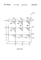
- FIG. 36 is an embodiment of a dual waveguide structure for high density packing architectures with permanent turning mirror and asymmetric loss crossing region.
- FIG. 37 is an embodiment of a switched waveguide array with TIR switches.
- FIG. 38 is an embodiment of a switched waveguide array with grating switches.
- FIG. 39A is an embodiment of an m ⁇ m communications switch array with system control lines.
- FIG. 39B is an embodiment of a 3 ⁇ 3 switch array with WDM capability.
- FIG. 40 is an embodiment of a two dimensional switching array with pixel elements.
- FIG. 41 is an embodiment of a one dimensional switching array with pixel elements coupled to data tracks.
- FIG. 42 is an embodiment of a switchable spectrum analyzer using selectable grating reflector sections and a detector array.
- FIG. 43 is an illustration of a poled acoustic multilayer interferometric structure.
- FIG. 44 is an illustration of a poled acoustic transducer.
- FIG. 45 is an embodiment of a tuned coherent detector of multi-frequency light waves.
- FIG. 46 is an embodiment of a low loss switchable waveguide splitter using a single poled region.
- FIG. 47 is an embodiment of a low loss switchable waveguide splitter using multiple poled regions.
- FIG. 48 is an illustration of the key design elements for a 1 ⁇ 3 waveguide splitter.
- FIG. 49 is a multiple layer stack of active waveguide devices shown as an adjustable phased array modulator.
- FIG. 50 is an embodiment of an adjustable waveguide attenuator of the prior art.
- FIG. 51 is an embodiment of a multiple poled segment adjustable waveguide attenuator.
- FIG. 52 is an embodiment of a structure with widened bandwidth using an angle-broadened poled grating.
- FIG. 53 is an embodiment of a structure with widened bandwidth using a curved waveguide.
- FIG. 54 is an embodiment of an electrically controllable poled lens.
- a device 11 of the present invention which is a patterned poled dielectric device.
- this device is an electrically-controllable stacked dielectric optical energy redirector, or more succinctly, an electrically-switchable mirror.
- the invention is a bulk optical reflector in a ferroelectric crystal 20 of lithium niobate.
- the electrically-controlled switching element is a poled grating 22, which consists of alternating poled domains of two types 36 and 38.
- a domain which may be of any shape or size, is a physical region within which certain material properties are approximately constant.
- a poled domain is a region in a material in which the molecular groups have a directionality and these groups are substantially aligned (or are partially aligned) in, or near, a direction called the poling direction.
- domains there are many types of domains including domains of aligned atomic structures in different directions, domains of aligned molecules or atomic structures with various modified parameters such as the nonlinear activity or the electro-optic coefficient, domains of atomic structures with no preferred direction, domains defined by regions activated by different electrodes, poled regions in which the poling direction varies systematically across the region such as occurs in the case of polymers and fused silica poled with localized electrodes, domains of randomly oriented molecules, and by extension, a random domain structure: domains of sub-domains which are randomly poled within the domain.
- a poled structure is a set of individual domains.
- a patterned poled region is a region in a material in which the domains within the region have been poled according to a spatial pattern, with more than one domain type.
- the boundaries of the pattern may also be somewhat irregular and not follow the imposed pattern perfectly, particularly if the poling process is not under complete control.
- the device is described as a patterned poled dielectric because an electric field is applied in controlling the device, so the material must be a dielectric in order to withstand the required field without damage.
- the poling process is also accomplished using an electric field, which the material must also withstand. In general, we mean by dielectric the capability of the material to withstand the minimum electric fields needed for the application.
- an optical input beam 40 is incident on and through the crystal, along an optical axis.
- the optical axis is normal to the phase front of the beam and is defined by the mean location of the propagating beam across its intensity profile at the phase front.
- the optical axis is straight in a uniform material, but may bend in several situations including curved waveguides, nonuniform media, and in reflective or diffractive structures.
- the input beam 40 preferably has a sufficiently small spot size 21 throughout the crystal length so that it is not apertured by the crystal, causing undesirable power loss and mode conversion.
- the domains 36 and 38 must penetrate a sufficient distance through the substrate 20 so that they overlap at least a portion of the input beam 40.
- the grating 22 lies transverse of the input beam 40. This means the planes 34 of the grating 22 are transverse of the axis of the input beam 40. For two lines (or a line and a plane, or two planes) to be transverse of each other we mean that they are not parallel. Since the grating is transverse of the beam 40, the beam passes through at least a portion of the structure of the grating 22.
- the optical beam 40 is derived from an optical frequency source (not shown) and has a wavelength such that the beam is not substantially absorbed in the crystal, and such that the photorefractive effect does not distort the beam significantly.
- the optical frequency source means may include one or more optical exciters capable of supplying sufficient brightness within the wavelength acceptance of the grating reflector 22 to produce a useful switched output beam 44.
- the output beam may be coupled to other elements on the same substrate, or it may be coupled to external devices, in which ease the output surface through which beam 44 emerges is preferably antireflection coated.
- the antireflection coating may be a multilayer dielectric coating, a single quarter wave layer of a material with almost the appropriate index of refraction, or a sol-gel coating.
- the exciter may be any light source including a laser, a light emitting diode, an are lamp, a discharge, or even a filament, provided that the desired spectral brightness is achieved.
- the desired spectral brightness may be supplied directly from one or more exciters, indirectly from one or more frequency converted (doubled, mixed, or parametrically amplified) exciters, or in combination with several of the above alternatives.
- Absorption effects will limit the wavelength to the range from about 400 to 4000 nm.
- the effect of the photorefractive phenomenon varies with the configuration, the wavelength, dopants, and the poling structure, and we assume here that it has been brought under control so that any beam distortion remains within acceptable limits.
- the grating 22 is formed or defined by the boundaries 34 between alternating domains of two different types.
- the first type of domain 36 has a different electro-optic (E-O) coefficient than the second type of domain 38, so that a uniform electric field applied between the electrodes 24 and 26 results in different changes in the index of refraction in the two types of domains.
- E-O electro-optic
- the index of refraction changes the phase velocity of the wave, there is an impedance mismatch between the regions of different index or phase velocity. It is advantageous to accomplish such an index change with material in which the regions 36 have a reverse sense relative to the poling direction of the other domain type 38 and the original wafer 20, as shown by the poling sense arrows 39, 41.
- reverse sense we mean the poling direction is opposite to some reference direction.
- a uniform electric field applied to the structure 22 produces a modulated index of refraction.
- the pattern of index modulation adds to the pre-existing index of refraction distribution; the simplest configuration has no index modulation in the absence of the applied electric field, and develops an index grating linearly in response to the applied field.
- a period 48 for the grating 22 is the distance between two domain boundaries entirely including a region corresponding to each domain type.
- index of refraction grating is obtained by applying a strain field to the poled regions.
- the photoelastic response of the material produces different index of refraction changes in the different poled regions.
- the strain field may be applied permanently by, for example, laying down a film on top of the substrate at a high temperature and then cooling to room temperature.
- a concentration of strain may be achieved by etching away a stripe of the film, for example.
- the poled elements 36 and 38 alternate across the grating 22 with no space between them. If additional domain types are available, more complicated patterns of alternation are possible with domains separated by variable distances of the different domain types.
- the grating 22 is a uniformly periodic grating as shown in FIG. 2 so that the domain types contained in one period along the length of the grating 22 are reproduced in the other periods. For other applications, it is advantageous to modify the period to obtain advantages such as multiple spectral peaks or a broader spectral bandwidth.
- grating we mean an array of distinguishable structures, including all possible variations of geometry and periodicity.
- a periodic index grating is capable of supplying virtual photons in an interaction between optical beams.
- This means the grating structure is capable of supplying momentum, but not energy, to the interaction.
- the grating periodicity defines the momentum which is available to the interaction.
- the grating strength determines the "intensity" of the virtual photon beam.
- the number of periods in the section of the grating traversed by the optical beam determines the bandwidth of the virtual photon momenta which are available. Because of the bandwidth limitation, the interaction can only proceed within a specific range (or ranges) of optical frequencies. Grating devices are therefore inherently frequency selective, and typically operate around a nominal wavelength.
- the photons of the input beam 40 have the same optical frequency as the photons of the output beams 44 and 42, so energy conservation is observed.
- the momentum of the photons in input beam 40 and diverted output beam 44 are not the same; for the reflection process to occur, the change in momentum must be supplied by the grating 22 as illustrated by the vector diagram 43 associated with FIG. 2.
- the grating 22 supplies a virtual (with momentum but no energy) photon to the interaction to enable the conservation of momentum.
- the magnitude of the momentum vector is also called the propagation constant.
- the momentum vector K g 2 ⁇ / ⁇ points perpendicular to the grating surfaces, and it can have any wavelength value A which is present in the Fourier transform of the grating.
- the optical spacing (the width of the grating lines and spaces) associated with the propagation constant K g of a 50% duty cycle grating is therefore ⁇ /2.
- the frequency of interaction may also be tuned by adjusting for example the index of refraction of the optical beams, or the grating period by thermal expansion or other means.
- an index structure may have a spectrum of wavelengths and vector directions which can be contributed to the interaction.
- multiple virtual photons may be contributed to an interaction in a so-called “higher order” grating interaction.
- a "higher order" grating is one which has a period which is related to the required period for momentum conservation by division by an integer. The required momentum virtual photon is obtained from the harmonics of the "higher order" grating.
- the condition that momentum be conserved by the process is commonly called the Bragg condition, so the gratings of this invention are Bragg gratings, and the incidence angle on the gratings is the Bragg angle for the in-band or resonant frequency component.
- This dual conservation of energy and momentum is required for any energy beam interaction, whether the energy beam is optical, microwave, acoustic, or any other wavelike energy form consisting of a time-variable energy field. Only the implementation of the grating may change, to produce an impedance modulation for the different forms of energy so that the pattern of the structure can couple with the wavelike energy form.
- the index grating functions as a frequency-selective optical energy router or reflector.
- a beam of a characteristic frequency within the interaction bandwidth (capable of interacting with one or more of the virtual photons) is known as an in-band beam, while energy beams of other frequencies are known as out-of-band beams.
- the grating 22 has a frequency bandwidth which corresponds to the full width at half maximum of the reflection efficiency of the grating as a function of optical frequency. When the index grating is present (the grating is "on”), a beam having an optical frequency within the bandwidth of the grating is reflected from the grating at the angle 46 around a normal 47 to the grating structure.
- An out-of-band beam transmits through the crystal along the same optical axis and in the same direction as the input beam, forming part of the transmitted output beam 42.
- An electric field applied in the region including the grating controls the strength of the index modulation (which can also be thought of as the intensity of the virtual photons), adjusting the ratio of the power in the transmitted output beam 42 to that in the reflected output beam 44.
- n index of refraction of the beam
- L length of the grating
- the effective length is smaller than the total length of the grating, increasing the bandwidth.
- the two types of domains may exhibit an index difference before an electric field is applied.
- a permanent index grating accompanies the poled switchable index grating.
- the net modulation in the index of refraction (the grating strength) may be increased or decreased, depending on the polarity.
- the "grating off" situation index grating value near zero) is then achieved at a specific value of applied field.
- the grating can then be turned “on” by applying any other field strength. If the polarity of the applied field is reversed, for example, an index grating is produced with twice the strength of the original permanent grating.
- the poled grating structure of our invention has two major advantages over the prior art.
- First, the poled domain structures can have very sharp boundaries, providing a strong Fourier coefficient at virtual photon momenta which are multiples of the momentum corresponding to the basic grating period. This is very useful in cases where it is impractical to perform lithography with the required small feature size.
- Second, strong index modulation gratings can be made even if the optical mode dimension is large compared to the grating period. This is not possible in a uniformly poled substrate excited by patterned electrodes, because the electric field modulation decays exponentially with distance away from the plane of the electrode array, losing most of the modulation within a distance equal to the grating period.
- the poling process can create poled features with an extremely high aspect ratio, or the ratio of depth of the domain to its width. Using an electric field poling technique, aspect ratios in excess of 250:1 have been fabricated. Because we use essentially uniform electrodes, we get good electrostatic penetration; with deep domain walls, good modulation is available across the entire beam.
- the grating may also be a two dimensional array of index changes, in which case the grating has periodicities in two dimensions.
- the virtual photon contributed by the grating can then contribute momentum in two dimensions. This might be useful, for example, in an application with several output beams from a single grating.
- the ferroelectric crystal is a commercially-available, z-cut, lithium niobate single-crystal wafer. Other cuts, including x-, y-, and angle-cuts can also be used, depending on the poling method and the desired orientation of the poled domains.
- the fabrication steps include primarily poling and electrode fabrication. Prior to processing, the crystal is cleaned (for example by oxygen plasma ashing) to remove all hydrocarbons and other contaminants remaining from the polishing and handling processes. To control the poling, a mask and processing electrodes are used to create a pattern of applied electric field at the surface of and through the wafer, as described in U.S. patent application No. 08/239,799 filed May 9, 1994.
- the poling pattern is adjusted to produce the poled domain inversion in regions 36 during the application of the poling field.
- a silica layer several microns thick is deposited on the -z surface 23 of the wafer 20. This film is thinned or removed over the regions 36 where domain inversion is desired, a liquid electrode or deposited metal film is used to make a good equipotential surface over the patterned silica, and an electric field exceeding approximately 24 kV/mm is applied with the +z surface 23 at a higher potential than the -z surface 25.
- ferroelectric crystals of lithium niobate have been poled to create patterns of two domain types which are of reverse polarity (domain inversion). The magnitude of the electro-optic coefficient for the two types of domains is identical, although with a reverse polarity.
- domain inversion has been achieved in ferroelectrics using in-diffusion, ion-exchange, and alternate electric field poling techniques.
- Domain formation by thermally-enhanced in-diffusion has been demonstrated in lithium niobate, using titanium.
- the triangular shape of the inverted region limits the interaction efficiency for small domain size, however, and is useful mainly in waveguide devices with long periods.
- Patterned poling via ion exchange has been demonstrated in KTP in a salt bath containing rubidium and barium ions, in which the potassium ions in the crystal were exchanged for the rubidium ions.
- Electric field poling using alternate techniques to the preferred one have also been demonstrated in both lithium niobate and lithium tantalate.
- Solid ferroelectric materials including KTP and barium titanate
- KTP and barium titanate can be poled by electric field domain-inversion techniques.
- Solid means holding its structure for a certain period of time, such as cooled fluids, glasses, crosslinked polymers, etc.
- Gratings with different characteristics are generated by the different techniques. Electric field poling aligns the domains in the crystal without producing an intrinsic change in the index of refraction, while the ion-exchange and diffusion techniques do create a index change in the poled regions. A permanent index grating accompanies the switchable poled grating when these latter methods are used.
- the second domain type may be reverse poled, unpoled, or poled at another angle, and it may be distinguished by possessing a distinct electrical activity coefficient, (e.g. the electro-optic or the piezo--optic coefficient).
- a distinct electrical activity coefficient e.g. the electro-optic or the piezo--optic coefficient.
- the poled domains will have a uniform orientation while the orientation in the other domains will be random.
- the performance of the device will be affected by the details of the random pattern, depending on the type of device.
- the second domains may be oriented perpendicular to the first or at another angle, and the difference in the electrical response can still produce a useful electronically controlled structure.
- the poled domains may also be formed in a material which was previously unpoled and randomly oriented on a molecular scale, such as in fused silica or polymers. The poling process orients the structure of the material to form the first domain type, while the second domain type consists of the unpoled or randomly oriented regions in the material.
- the poled structure can be formed by selectively changing or destroying the electrical activity coefficient in regions corresponding to the second domain type.
- the orientation of the atomic structures in these regions does not need to be altered: if the electrical activity is changed in the second domain region, the domains are different.
- the electro-optic coefficient may be disabled by irradiation, producing regions of electrical activity where the irradiation is masked off. A similar effect has been demonstrated in lithium niobate, where proton exchange destroys the nonlinear coefficient. Modification of the electro-optic coefficient can also be achieved by optical radiation, electron bombardment, and/or ion bombardment in many other materials, including most nonlinear materials such as KTP and lithium tantalate.
- this polarization In a z-cut crystal, this polarization is called TM. (In TE polarization, the electric vector lies in the plane of the crystal surface. The only other significant nonlinear coefficient is r 15 , which couples TE and TM waves upon the application of an electric field E 1 or E 2 .)
- the grating reflector of FIG. 2 has a strong angular dependence.
- the Brewster angle for a weak index change is 45°, so the gratings will totally transmit any TE polarized wave when the planes of the grating are disposed at and angle of 45° with respect to the phase front of the light beam.
- the device may therefore be used as a polarizer.
- the reflected beam will always be essentially polarized at 45° incidence.
- the reflection coefficient for the TM wave is high, which can be arranged with enough grating periods and a high applied field, the extinction ratio of the polarizer can also be very high in the forward direction.
- the reflection coefficient for the TM wave is high, which can be arranged with enough grating periods and a high applied field, the extinction ratio of the polarizer can also be very high in the forward direction.
- a total internal reflection device operating at grazing incidence is far from Brewster's angle and has little difference in reflection due to this effect.
- the wafer material can be any polable solid dielectric material, including ferroelectrics, polymer films, and some amorphous materials such as fused silica which can also be poled for producing many useful devices according to the invention.
- the poled material may also be a thin film deposited on a substrate of a second material.
- Many of the polable thin films such as fused silica, lithium niobate, potassium niobate, barium titanate, zinc oxide, II-VI materials, and various polymers, have been successfully deposited on a substrate.
- a wide variety of substrates have been used, including MgO, silicon, gallium arsenide, lithium niobate, and various glasses, including quartz and fused silica.
- electro-optic materials which are materials having an index change induced by an applied electric field.
- a first electrode 24 and a second electrode 26 confront the dielectric material in order to provide a means to create the electric field which controls the grating.
- Confronting a material means placed close to the material but not necessarily touching, approximately aligned to the surface of the material but not necessarily with a constant gap dimension, and includes situations with additional material of varying dimensions placed on top of the material.
- the electrodes 24 and 26, consisting of an electrically-conductive material, are preferably laid out on opposing surfaces of the crystal in a spatially delimited manner using standard deposition techniques.
- the electrodes are referred to as being on opposing planes even though the surfaces may be curved and/or non-parallel as part of a larger geometry.
- the electrodes may be formed by any material that provides sufficient transport of electrical charge to achieve an adequate field strength to activate the poled grating in a time consistent with the application.
- the electrodes could alternatively consist of metals such as aluminum, gold, titanium, chromium, etc., conductive paint, epoxy, semiconducting material, or optically transparent materials such as oxides of indium and tin, and liquid conductors such as salt solutions. They may also confront the surfaces 23 and 25 with a gap filled with air, an optically transparent buffer layer, and/or other material.
- the electrodes are the electric field creating means because the application of a voltage to an electrode establishes an electric field pattern which is determined by the electrode. A voltage and current supply is of course also needed.
- the electrodes are placed so that the control electric field is applied through the active volume of the invention, which may consist of a pattern poled region or a grating.
- the coating may be best to incorporate a coating deposited below the electrode, to reduce the optical loss which occurs when a portion of the guided wave mode extends to the metallic electrode.
- the coating should be thin enough to maintain high electric field at the surface in the case of multiple electrodes mounted on the same surface, but thick enough to reduce the optical loss. Mother coating is also useful above the electrodes to reduce the probability of breakdown.
- a voltage control source 32 (or potential source) provides the electrical potential to drive the electrodes through connections 30 to activate the grating.
- the activated electrodes are polarized relative to each other according to the polarity of the applied voltage.
- the voltage of the source produces a large enough electric field through the poled regions to switch a significant amount of light into the switched output beam 44.
- the voltage of the source is variable to provide a means to control the ratio of power in the two output beams. Substantially all of the input beam may be reflected with a long grating if the electric field is sufficiently high, forming an electrically activated mirror. For lower electric fields, the grating forms a partial reflector.
- the voltage control source may be a battery, an electrical transformer, a gas powered generator, or any other type of controllable source of electrical current and potential.
- the control means 32 may also incorporate a controller which generates a time dependent voltage, and which supplies the current to change the voltage on the electrodes 24 and 26 at the frequencies required by the application.
- the control means 32 may also have multiple outputs capable of controlling multiple devices, and which might be sequenced temporally according to some pattern.
- the source 32 may have control inputs for manual or electronic control of its function by computer or by another instrument.
- this embodiment is an electrically-controlled, frequency-selective waveguide retroreflector. All of the optical beams in this device are confined in two dimensions by an optical waveguide 64, which traverses one surface of the polable dielectric material that forms the substrate 60 of the device 61.
- a waveguide is any structure which permits the propagation of a wave throughout its length despite diffractive effects, and possibly curvature of the guide structure.
- An optical waveguide is defined by an extended region of increased index of refraction relative to the surrounding medium. The strength of the guiding, or the confinement, of the wave depends on the wavelength, the index difference and the guide width. Stronger confinement leads generally to narrower modes.
- a waveguide may support multiple optical modes or only a single mode, depending on the strength of the confinement. In general, an optical mode is distinguished by its electromagnetic field geometry in two dimensions, by its polarization state, and by its wavelength. The polarization state of a wave guided in a birefringent material or an asymmetric waveguide is typically linear polarized.
- the general polarization state may contain a component of nonparallel polarization as well as elliptical and unpolarized components, particularly if the wave has a large bandwidth.
- the waveguide is implemented on the surface of a substrate so that there is an asymmetry in the index of refraction above and below the waveguide, there is a cutoff value in index difference or waveguide width below which no mode is confined.
- a waveguide may be implemented in a substrate (e.g.
- the optical mode which propagates in the waveguide has a transverse dimension which is related to all of the confinement parameters, not just the waveguide width.
- the substrate is preferably a single crystal of lithium niobate, forming a chip which has two opposing faces 63 and 65 which are separated by the thickness of the wafer.
- the opposing faces need not be parallel or even flat.
- the waveguide is preferably formed by a well-established technique such as annealed proton exchange (APE) on face 63. Alternatively, ions other than protons may also be indiffused or ion exchanged into the substrate material.
- APE waveguide increases the crystal extraordinary refractive index, forming a waveguide for light polarized along the z-axis. For a z-cut crystal, this corresponds to a TM polarized mode.
- Waveguides formed by alternate techniques, such as titanium indiffusion in lithium niobate may support both the TM and TE polarizations.
- the waveguide is designed to support only a single lowest order transverse mode, eliminating the complexities associated with higher order modes.
- the higher order transverse modes have different propagation constants than the lowest order mode, and higher scattering loss, which can be problems in some applications.
- multimode waveguides might be preferred for some applications, such as for high power propagation.
- a photomask for the waveguide is generated and the pattern is transferred to a masking material on the substrate, by one of many well known lithographic processes.
- the mask material may be SiO 2 , tantalum or other metals, or other acid resisting materials.
- the masked substrate material is immersed in molten benzoic acid to exchange protons from the acid for lithium ions in the crystal.
- the resulting step index waveguide may then be annealed for several hours at around 300° C. to diffuse the protons deeper into the crystal and create a low-loss waveguide with high electrical activity coefficients.
- planar and two dimensional ridge or strip-loaded waveguides can be formed.
- Planar waveguides may be formed by depositing the electrically active material on a substrate of lower index. Deposition techniques for waveguide fabrication are well-known and include liquid phase epitaxy (LPE), molecular beam epitaxy (MBE), flame hydrolysis, spinning, and sputtering. Ridge waveguides can be formed from these planar guides by using processes such as lift-off, wet etch, or dry etch such as reactive ion etching (RIE). Planar guides can also be used in the present invention, particularly in devices using a variable angle of diffraction off the grating.
- LPE liquid phase epitaxy
- MBE molecular beam epitaxy
- RIE reactive ion etching
- the grating 62 in this embodiment is disposed normal to the optical waveguide 64 which traverses the substrate.
- the grating is composed of a first type 66 and second type 68 of domain, which do not necessarily extend through the substrate.
- the inverted domains 66 typically extend to a finite depth in the material.
- the partial domains may also be formed when the poling is achieved by destroying the electrical activity of the material (or reducing the electro-optic activity) by a technique such as ion bombardment or UV irradiation.
- the optical input beam 80 is incident on and is coupled into the waveguide.
- Coupling refers to the process of transferring power from one region into another across some kind of generalized boundary such as across an interface, or between two parallel or angled waveguides, or between a planar guide and a stripe guide, or between single mode and multimode waveguides, etc.
- the grating When the grating is on, a portion of the input beam is coupled back into a retroreflected output beam 82. While the retroreflection of the grating need not be perfect, i.e. the grating may reflect the light to within a few degrees of the reverse direction, the waveguide captures most of this light and forms a perfectly retroreflected beam.
- the imperfection of the retroreflection results in a coupling loss of the retroreflected beam into the waveguide 64.
- the grating is off (when the controlling electrical field is adjusted to the "off" position in which the index grating has a minimum value near zero, typically at zero field), the input beam continues to propagate in the same direction through the waveguide to form a transmitted output beam 84.
- the strength of the grating can be varied with the voltage source 76 to control the ratio of the power in the two output beams.
- a first electrode 70 and second 72 electrode confront opposing faces of the dielectric material 60.
- the substrate is a dielectric because it is capable of withstanding an applied electric field without damage, but it need not be a perfect insulator as long as the current flow does not adversely affect the performance of the device.
- the electrodes may be formed of any electrically conducting material. There must also be a means for creating an electric field through the dielectric material using the first electrode structure.
- the electrodes bridge at least two of the elements of the first type of poled structure that forms the grating. This means the electric field produced by the electrodes penetrates into at least the two elements. Thus, these elements can be activated by the field.
- Two wires 74 preferably connect the voltage control source 76 to the two electrodes to provide an electric field in the region formed by the intersection of the waveguide 64 and the poled structure 62.
- the wires may be formed from any material and in any geometry with sufficient conductivity at the operating frequency to allow charging the electrodes as desired for the application.
- the wires may be round, flat, coaxial cables, or integrated lead pattern conductors, and they may be resistors, capacitors, semiconductors, or leaky insulators.
- the electrodes can be arranged in any manner that allows an electric field to be applied across the electrically active material.
- the electrodes may be interspersed in different layers on a substrate, with the active material between the electrodes. This configuration enables high electric fields to be produced with low voltages, and is particularly useful for amorphous active materials, such as silica and some polymers, which can be deposited over the electrode material.
- the poled structure 62 is preferably deeper than the waveguide so that the intersection between the waveguide 64 and the poled structure 62 has the transverse dimensions of the mode in the waveguide and the longitudinal dimensions of the grating.
- FIGS. 4, 5 and 6 show alternate electrode configurations in which the electrodes are disposed on a common face of the dielectric material 189. These configurations are especially useful for embodiments of the present invention that use a waveguide 180 to guide an optical beam, since the samesurface electrode configurations permit high electric fields at low voltage. These electrode structures are of particular interest for low voltage control of the grating 182 because of the proximity of the electrodes to the section of the waveguide which traverses the grating. In the electrode configuration 186 depicted in FIG. 4, the first electrode 170 and second electrode 172 confront the dielectric material on the same surface. These electrodes are referred to as being on a common plane even though the surface may be curved as part of a larger geometry.
- the first electrode is placed above a portion of the waveguide that contains several grating elements, each of which consists of alternate regions of a first type of domain 184 and a second type of domain 185.
- the second electrode is positioned around the first electrode.
- the distance between the electrodes along the waveguide is approximately constant along the axis of the waveguide for cases where a uniform field along the axis of the waveguide is desired.
- the electrode spacing may also be varied to taper the field strength, as shown schematically in the device 188 of FIG. 6.
- a voltage source 174 connected between the two electrodes disposed as shown in FIG. 4, is capable of generating electric fields between the electrodes.
- the electric field vectors 176 have their largest component perpendicular to the surface of the material, in the region of the electrically-active waveguide.
- this electric field structure activates the largest electro-optic coefficient r 33 , creating a change in index for a TM polarized optical beam.
- the strength of a first order grating is 40 cm -1 .
- a means 178 for contacting the electrodes to a voltage source is required for each of the electrode configurations.
- an electrically conducting material such as a wire
- each electrode typically has a section, or pad, or contact, to which the wire is contacted.
- the pads are preferably of large enough size to reduce placement tolerances on the electrical contact means for easier bonding.
- the wire can then be contacted to the pads using a technique such as wire bonding by ultrasonic waves, heating, or conductive epoxy.
- a spring-loaded conductor plate can be placed in direct contact with the electrode to make the required electrical connection to the voltage source.
- the electrodes are typically large enough and function as the contact pads by themselves.
- FIG. 5 Another realization 187 of the same-surface electrode structure is shown in FIG. 5, wherein the first electrode 171 and second electrode 173 are placed on either side of the optical waveguide.
- the electric field vectors 177 have their largest component parallel to the substrate surface.
- the electro-optic coefficient that creates a change in index for a TM polarized optical wave and the applied electric field is r 33 .
- the first order grating coupling constant is 12 cm -1 .
- the active electro-optic coefficients are switched for the two configurations.
- the appropriate coefficient is r 33
- the electro-optic coefficient used is r 33 . Similar situations apply for x- or y-cut crystals, or intermediate cuts.
- the electrodes are asymmetrically arranged so that one electrode approximately covers the waveguide 180 and the other electrode is displaced somewhat to the side.
- the strong vertical field induced under the edges of the adjacent electrodes is made to pass predominantly through the waveguide region under one of the electrodes.
- the electrodes 175 and 179 have a separation from the center electrode 181 which is tapered.
- this configuration produces a tapered field strength, with the strong field towards the right and the weaker field towards the left.
- tapered we mean that any parameter has a generalized spatial variation from one value to another without specifying whether the variation is linear or even monotonic; the parameter may be a gap, a width, a density, an index, a thickness, a duty cycle, etc.
- the index changes induced in the poled domains towards the left of the waveguide 180 are therefore weaker than the index changes induced towards the right.
- the taper might be useful to optimize the coupling of a specific input mode into a specific output mode.
- the voltage applied can range from a constant value to a rapidly varying or pulsed signal, and can be applied with either polarity applied between the electrodes.
- the value of the voltage is chosen to avoid catastrophic damage to the electrically-active material and surrounding materials in a given application.
- FIG. 7 and FIG. 8 show two embodiments of a electrically-controlled frequency-selective waveguide coupler.
- a pair of two-dimensional waveguides traverse one face of a dielectric material, and intersect at an angle 118 to make a tee, forming a three-port device.
- a grating 100 consisting of a first type 104 and second type 102 of domains, is disposed at an angle to the two guides in the intersection region between them (the volume jointly occupied by the optical modes in the two waveguides).
- the peak index change in the intersection region is preferably equal to the peak index change in the waveguides.
- the peak index change in the intersection region is twice the index change in the waveguides, which is not needed.
- the periodicity and angle of the grating is chosen such that the reflection process is phase matched by the momentum of a virtual photon within the bandwidth of the grating.
- the angle of incidence of the input beam is equal to the angle of diffraction off the grating. In this case, the bisector of the angle between the two guides is normal to the domain boundaries of the grating in the plane of the waveguide.
- An input beam 112 is incident on and is coupled into the first waveguide 106.
- a first electrode 120 and second electrode 122 are laid out on the same face of the dielectric material so that an electric field is created in the intersection region between the waveguides, when a voltage source 124 connected to the two electrodes by conductors 126 is turned on.
- the electric field controls the strength of the grating in the intersection region via the electro-optic effect, coupling the in-band beam from the first waveguide into the second waveguide to form a reflected output beam 114.
- the input beam continues to propagate predominantly down the first waveguide segment to form a transmitted output beam 116 with very little loss.
- counter-propagating beams can be used in the waveguide so that the input beam enters though the second waveguide 108, and is switched into the output waveguide 106 by interacting with the grating.
- the grating strength is preferably spatially distributed in a nonuniform manner so that a lowest order Gaussian mode entering waveguide 106 is coupled into the lowest order Gaussian mode of waveguide 108.
- the grating strength can be modulated by adjusting the geometry of the electrode, by adjusting the gaps between the electrodes, and by adjusting the duty cycle of the grating.
- the bandwidth of the grating may also be enhanced by one of a number of well known techniques such as chirping, phase shifting, and the use of multiple period structures.
- the size of the coupling region is limited, in the geometry of FIGS. 7 and 8 by the size of the intersection region between the guides where their modes overlap. To obtain a high net interaction strength for a given electric field strength, it is desirable to increase the size of the waveguides to produce a larger intersection. However, large waveguides are multimode, which may not be desirable for some applications. If adiabatic expansions and contractions are used, the advantages of both a large intersection region and single mode waveguides can be obtained simultaneously.
- the input waveguide 106 begins as a narrow waveguide and is increased in width adiabatically as the intersection region is approached.
- the output waveguide 108 has a large width at the intersection to capture most of the reflected light, and it is tapered down in width adiabatically to a narrow waveguide.
- the idea of adiabatic tapering of an input and/or an output waveguide can be applied to many of the interactions described herein,
- the two waveguides 136 and 138 intersect at an angle 158 to make an x intersection, forming a four-port device.
- This device is a particularly versatile waveguide switch, since two switching operations occur simultaneously (beam 142 into beams 146 and 148, and beam 144 into beams 148 and 146).
- the grating 130 consisting of a first type 134 and second type 132 of domains, is disposed at an angle to the two guides in the intersection region between them.
- the angle of the grating is preferably chosen such that the bisector of the angle between the two guides is normal to the domain boundaries of the grating, in the plane of the waveguide.
- a first input beam 142 is incident on and is coupled into the first waveguide 136 and a second input beam 144 is coupled into the second waveguide 138.
- a first electrode 150 and second electrode 152 are laid out on the dielectric material so that an electric field is created in the intersection region between the waveguides, when a voltage source 154 connected between the two electrodes is turned on. The electric field controls the strength of the index grating in the intersection region through the electro-optic effect.
- the grating is on, a portion of the in-band component of the first input beam is coupled from the first waveguide to the second waveguide to form a first output beam 146.
- the in-band component of the second input beam from the second waveguide is coupled into the first waveguide to form the second output beam 148.
- the out-of-band components of the two beams, and any unswitched components of the in-band beams continue to propagate down their respective waveguides to form additional portions of the appropriate output beams.
- a single frequency component in the two input beams can be switched between the two output beams.
- the waveguide may only be a segment, in which case it is connected to other optical components located either off the substrate, or integrated onto the same substrate.
- the waveguide segment could be connected to pump lasers, optical fibers, crossing waveguides, other switchable gratings, mirror devices, and other elements.
- An array of crossing waveguide switches would comprise an optical switching network.
- FIG. 9 a further embodiment of the waveguide coupling switch is shown.
- the domain walls of the grating are now disposed at a non-normal angle to the surface 157 of the crystal 158, so that the input beam 159 in waveguide 160 is reflected out of the plane of the crystal to form a reflected output beam 161.
- An unreflected beam continues to propagate through the waveguide to form a transmitted output beam 162.
- a second electrode structure 164 which may be optically absorbing, is disposed on the material.
- the second electrode may be arranged in one of many alternate configurations: surrounding the first electrode as in FIG. 7, on opposite sides of the material 158 as on FIG. 2, tapered similar to the configuration shown in FIG. 6.
- the electrodes are connected with two wires 156 to a voltage source 154, which controls the power splitting ratio of the in band beam between the transmitted beam 162 and the reflected beam 161.
- the electrode configuration could be as shown in FIG. 5, in which case both electrodes may be opaque.
- the domain walls are preferably formed by electric field poling of a ferroelectric crystal which is cut at an angle to the z-axis 165. Since the electric field poled domains travel preferentially down the z axis, poling an angle-cut crystal by this technique results in domain boundaries parallel to the z axis, at the same angle to the surface.
- the angle 166 of the cut of the crystal is preferably 45° so that light propagating in the plane of the crystal may be reflected out of the substrate normal to the surface of the material (any angle may be used).
- the domains shown in FIG. 9 are planar, but can also be configured in more general configurations. A planar grating will produce a flat output phase front from a flat input phase front.
- a collimated input beam will produce a collimated output beam.
- the device is useful as a bulk reflector for example if a beam is incident from outside the device, or if the waveguide is brought to an end within the device with some distance between the end of the waveguide and the poled reflector. In some cases, however, it may be desirable to produce a curved output phase front from a collimated beam, as in the case of some applications requiring focussing, such as reading data from a disk.
- a set of curved domains may be poled into the bulk of the material since the domain inversion propagates preferentially along the z axis.
- a concave (or convex) set of domains may therefore be formed which create a cylindrical lens when excited by a field. Wedges and more complicated volume structures oriented at an angle to the surface may be formed by the same process.
- a z-cut crystal can be used as the substrate if the poling technique causes the domain boundaries to propagate at an angle to the z-axis.
- titanium (Ti) indiffusion in a z-cut crystal of lithium niobate produces triangular domains that would be appropriate for reflecting the beam out of the surface of the crystal.
- the angle of the domains formed by in-diffusion with respect to the surface is typically about 30°, so that an input beam incident on the grating will be reflected out of the surface at an angle of about 60° to the surface of the crystal.
- the output beam may then be extracted with a prism, or from the rear surface (which may be polished at an angle) after a total internal reflection from the top surface.
- the electrode structure shown excites both an E 3 component, and either an E 1 or an E 2 component.
- a TM polarized input wave 159 experiences an index change which is a combination of the extraordinary and the ordinary index changes.
- FIG. 10 there is shown an embodiment of a switchable waveguide directional coupler.
- a first waveguide 204 is substantially parallel to a second waveguide 206, over a certain length. While the beams propagate adjacent each other and in a similar direction, their central axes are displaced. The central axes are never brought coaxial so that the waveguides do not intersect. However, the waveguide segments are in close proximity in a location defined by the length of the coupler, so that the transverse profiles of the optical modes of the two waveguides overlap to a large or small extent. The propagation of the two modes is then at least evanescently coupled (which means the exponential tails overlap). The evanescent portion of the mode field is the exponentially decaying portion outside the high index region of the waveguide.
- the effective index n eff is the ratio of the speed of light in a vacuum to the group velocity of propagation, which varies according to the mode in the waveguide.
- the value of n eff is determined by the overlap of the mode profile with the guided wave structure.
- the width of the two waveguides, and thus the propagation constants of the modes in the two waveguides, are different, so that coupling between the modes is not phasematched when the grating is off.
- the index of refraction profiles of the two waveguides may also be adjusted to create different propagation constants.
- any input beam 210 in the first waveguide will continue to propagate in that waveguide to form a transmitted output beam 214 exiting the first waveguide 204.
- the grating makes up the difference in the propagation constants of the two waveguides so that coupling between the two modes is phasematched, and an in-band output beam 212 exits the second waveguide 206.
- the grating period ⁇ is chosen so that the magnitude of the difference of the propagation constants in the two waveguides is equal to the grating constant (within an error tolerance).
- the propagation constants of the two waveguides may alternately be chosen to be equal, so that coupling between the two waveguides occurs when the grating is off. In this case, turning the grating on reduces the coupling between the two guides.
- the strength of the grating determines a coupling constant, which defines the level of coupling between the two waveguides.
- the power transfers sinusoidally back and forth between the guides, so that coupling initially occurs from the first waveguide to the second, and then back to the first waveguide.
- the distance between two locations where the power is maximized in a given waveguide mode is known as the beat length of the coupled waveguides.
- the beat length depends on the strength of the grating.
- a first electrode 220 and second electrode 222 are positioned on the material surface to create an electric field across the grating region 202 when a voltage is applied between the two electrodes.
- a voltage source 226 is connected to the two electrodes with an electrically conductive material 224. The strength of the grating, and thus the beat length between the two waveguides, is controlled by the voltage applied across the grating.
- the propagation constants of the two guides are strongly dependent on wavelength. Since the momentum of the virtual photon is essentially or dominantly fixed (i.e. determined by parameters which are not varied in an application), power is transferred to the second waveguide only in the vicinity of a single frequency with a frequency bandwidth depending on the length of the coupling region. Depending on the grating strength, an adjustable portion of the in-band input beam exits the second waveguide as the coupled output beam 212, while the out-of-band portion of the input beam exits the first waveguide as the transmitted output beam 214 along with the remainder of the in-band beam.
- the coupling between the two modes can be controlled electro-optically by several means, including changing the strength of the coupling between the modes, increasing the overlap of the modes, or changing the effective index of one of the waveguides.
- Electro-optically controlled coupling, described above, is the preferable method. In order to couple efficiently between the modes in the two waveguides, the input beam is forward-scattered, which requires the smallest grating period.
- the coupling grating can alternatively be implemented as a combination of permanent and switched gratings as described above in conjunction with FIG. 2.
- the substrate can be chemically etched to form a relief grating with exactly the same period as the poled structure.
- the etch can be accomplished without any further masking steps, since the different types of domains etch at different rates.
- hydrofluoric acid (HF) causes the -z domains of lithium niobate to etch significantly (>100 ⁇ ) faster than the +z domains.
- the regions consisting of the first type of domain are etched while the regions consisting of the second type of domain essentially remain unetched.
- This procedure produces a permanent coupling grating which can be used on its own to produce coupling between the two waveguides.
- the poled grating can be excited to produce an additive index of refraction grating which is superimposed on that of the etched substrate.
- the etch depth may be controlled so that the effective index change induced by the permanent etched grating can be partially or wholly compensated by the electro-optically induced grating when the electrodes are excited at one polarity, while the index grating is doubled at the other excitation polarity.
- a push-pull grating is thereby produced whereby the grating can be switched between an inactive state and a strongly active state.
- An etched grating is also useful when the etched region is filled with an electro-optical material, such as a polymer or an optically transparent liquid crystal, with a high electro-optic coefficient and an index close to that of the substrate.
- the filled etched region extends down into the optical beam.
- the index of the filler material is also varied around that of the rest of the waveguide.
- the overlap of the modes in the two waveguides can be electro-optically modified.
- the region between the two waveguides could have its refractive index raised. This reduces the confinement of the waveguides, and spreads the spatial extent of the individual modes towards each other, increasing the overlap.
- the region between the two waveguides may be reverse poled with respect to the polarity of the substrate traversed by the waveguides. If the electrode extends across both the waveguides and the intermediate region, an applied voltage will increase the index of the area between the waveguides while decreasing the index within the two waveguides. The resulting reduction in mode confinement thus increases the overlap and the coupling between the two modes.
- An adiabatic change means a very slow change compared to an equilibrium maintaining process which occurs at a definite rate. In this case, it means the change is slow compared to the rate of energy redistribution which occurs due to diffraction within the waveguide and which maintains the light in the mode characteristic to the waveguide.
- a third means to change the coupling between the two waveguides is to change the effective index of one of the waveguides relative to the other.
- the propagation constant of the guide is changed, which in turn alters the phasematching condition.
- This effect may be maximized by poling one of the waveguides so that its electro-optic coefficient has the opposite sign from that of the other waveguide.
- the coupling grating may be a permanent or a switched grating.
- a first electrode covers both waveguides and the region between them, while a second electrode may be disposed on both sides of the first electrode.
- An electric field applied between the two electrodes causes the propagation constant of one waveguide to increase, and that of the other waveguide to decrease, thus maximizing the difference in propagation constants.
- the grating coupling process is maximally efficient only at a particular difference in propagation constants. By tuning the applied voltage, the phasematching may be adjusted as desired. This effect can be used to create a wavelength tunable filter.
- the parallel waveguides shown in FIG. 10 may be nonparallel, and the waveguides may not even be straight. If it is desired, for instance, to spatially modify the interaction strength between the waveguides, this end can be accomplished by spatially adjusting the separation between the guides. These modifications may also, of course, be applied to the subsequent embodiments of parallel waveguide couplers described herein.
- FIGS. 12 and 13 there are shown alternate embodiments of the crossing waveguide coupler for controlling the profile of the reflected beam.
- the area covered by the grating does not extend entirely across the intersection region of the two waveguides.
- the power coupling structure 282 may distort the spatial profile of the mode 284 it couples into the output waveguide.
- a power coupler which is uniform in space and which uniformly covers the entire intersection region 280 between two waveguides disposed at a large angle to each other such as 90° will produce an output beam profile such as assymmetric profile 286.
- the power in the input beam decreases as it passes through the power coupling structure or grating.
- the near field profile of the reflected beam matches the monotonically decreasing power in the input beam.
- the disadvantage with the nonsymmetric profile 286 lies in single mode structures where only a fraction of the coupled power will remain in the waveguide. Much of the power will be lost from the guide.
- FIGS. 12 and 13 show ways to accomplish this end with geometrical arrangements of gratings. It is also possible to accomplish this end by spatially modulating the "duty cycle" of the grating within the power coupling region 282, by changing the order of the grating in selected regions, and in the case of electrically controlled coupling, by tapering the strength of the applied electric fields (by adjusting electrode spacing as illustrated in FIG. 6, or by adjusting the electrode duty cycle in the case of grating electrode structures).
- the duty cycle of a grating means the fraction of each period which is occupied by a given domain type; the duty cycle may vary with position.
- a device 300 with a modified grating structure is shown, in which the grating area 310 covers part, but not all of the rectangular intersection region of the two normal guides 316 and 318.
- the input beam 302 passes through guide 316 undetected to exit as output beam 308.
- the dimensions of the intersection region match the widths 304 and 305 of the two waveguides.
- the presence of a small region of power coupling structure at any point in the intersection region will result in local coupling between a given transverse segment of the beam profile in an input waveguide into a given transverse segment of the beam profile in an output waveguide.
- the reflected beam profile is constructed from the propagated sum of these phased-coupled contributions.
- the grating region 310 depicted is triangular in shape, with the points of the triangle 311,312, and 313.
- the shape of the grating region can be modified from the triangular, and the local grating strength can be modulated.
- the exact shape of the grating region which optimizes single mode coupling characteristic between the waveguides can be calculated with an established waveguide propagation technique, such as the beam propagation method.
- FIG. 13 A further embodiment of a single-mode coupling grating device 340 is shown in FIG. 13.
- the grating region 350 is a double convex shape, with one point at corner 351 common with waveguides 346 and 348 and beams 330 and 342, and the other point on opposite corner 352, common with both waveguides and beams 342 and 332.
- This structure has the advantage of reflecting most of the power in the middle of the beam, where the optical intensity is the highest, and thus better couples the power between the lowest order modes in the two waveguides 346 and 348.
- the optimal shape of the grating region again depends on the coupling constant of the grating.
- a first electrode 320 is disposed on the same surface of the substrate as the waveguide, over the grating region, and a second electrode 322 is disposed on the same surface around the first electrode.
- the distance between the two electrodes may be constant as illustrated in FIG. 13, or it may be tapered as illustrated in one dimension in FIG. 12.
- a voltage control source 324 is connected with two wires 326 to the two electrodes. An electric field can thus be applied through the grating region to activate one of the electro-optic coefficients and change the coupling between the input beam and the output beam.
- FIG. 12 also shows a tapered input waveguide segment 287 and a tapered output segment 289.
- An input beam 285 expands adiabatically through the tapered segment 287 to increase the intersection area and thereby increase the total reflection from grating 310.
- the grating is capable of reflecting the now-expanded beam 285 toward the output beam 308.
- the output waveguide may also contain a tapered segment 289 to reduce the witdth of the output beam. (Alternatively, the output beam may be kept wide if desired for later beam switching interactions.)
- the grating may extend beyond the intersection region of the two waveguides.
- a grating extended along the input waveguide enables residual transmitted light after the intersection region to be removed from the waveguide, typically into radiation modes.
- the extended grating minimizes crosstalk between optical channels in switching arrays, in which an individual waveguide may have more than one signal channel propagating along its length.
- FIGS. 14-17 Specifically contemplated by the invention is a means for tuning the grating.
- FIGS. 14-17 Several embodiments in which tuning is achieved are shown in FIGS. 14-17.
- FIG. 14 there is a bulk optical device 400 in which the strength and center wavelength of a normal incidence reflection grating are controlled by a single voltage source 426.
- This device consists of a patterned poled grating region 410, which is electro-optically activated by two electrodes 420 and 422 on opposing surfaces of the material and connected to 426 by conductors 424.
- the strength and the center frequency of the grating are tuned simultaneously by applying a single voltage between the two electrodes of the device.
- the average refractive index of the grating changes with the applied electric field, causing a change in the center wavelength of the grating that is proportional to the electric field.
- the average index is calculated over a single period of the grating in a periodic grating, by summing the weighted index changes in the various types of domains.
- the weighting factor is the physical length 416 and 418 of each domain type, along the optical path of the input beam 404.
- the condition for frequency tuning is that the weighted sum must not equal zero so that the average index changes as a result of the electric field.
- the product of the index of refraction and the physical distance traversed by an optical beam is known as the optical distance.
- the index of refraction is replaced by the effective index of refraction for waveguide devices.
- a 50% duty cycle is obtained in a grating with two types of domain if the average optical distance across the two types of domains is substantially equal (approximately equal within the error range determined by the needs of the application). The average is taken over many subsequent domains to allow for the possiblity of a chirped, nonperiodic, or other more general type of grating. In general the domains may have different indices of refraction as well as different electro-optic coefficients.
- the general condition for tuning is expressed in terms of the physical distance travelled in the different types of domains.
- the total optical phase advance is given by the optical distance travelled (times 2 ⁇ / ⁇ ).
- the change in the phase advance is given by the product of the applied electric field, the appropriate electro-optic coefficient, and the physical distance (times 2 ⁇ / ⁇ ).
- the grating strength is changed simultaneously with the wavelength in this structure, but such simultaneous change may be undesirable.
- the structure may be designed so that the operating point about which timing is accomplished maintains a sufficiently high grating strength for the application across the entire wavelength tuning range.
- a separate tuning structure may be used as is described below in reference to FIGS. 16 and 17.
- the change in the average refractive index can be achieved by many different means.
- One alternative is that of randomly non-electro-optically active domains 414 alternating with electro-optically active domains 412.
- the electro-optically active regions are poled domains, while the non-electro-optically active domains may be randomly poled or unpoled or radiation-disabled.
- the electric field causes an average increase in the index ⁇ n avg across the grating.
- ⁇ n avg is equal to the product of the index change in the active domains 412 times the duty cycle.
- the duty cycle is equal to the length 418 divided by the sum of the lengths 418 and 416.
- the tunability that can be achieved using this technique is ⁇ n avg in a poled-random structure, where ⁇ is the optical wavelength, and n is the original (effective) index of the material. Assuming a wavelength of 1.55 ⁇ m and a 10 V/ ⁇ m electric field in lithium niobate, the tuning range for a 50% duty cycle structure is 1.1 nm.
- the grating couples the beam into a retroreflecting output beam 402; otherwise the input beam forms a transmitted output beam 406. Contrast this behavior with that of a 50% duty cycle grating where the two domain types have the same electro-optic coefficients but opposite polarity, as in the case of domain inversion. In this latter case, there is no change in the average index of refraction since the change in index of the first domain type cancels with the change in index of the other domain type.
- a 50% duty cycle domain reversal grating does not time its center frequency.
- An alternate means to achieve an average effective index change in domain reversed gratings is to use a non-50% duty cycle for the poled domain area with unequal lengths 416 ⁇ 418.
- the tunability that can be obtained using this technique is (2D-1) ⁇ n ⁇ /n, where D is the duty cycle of the largest domain type (D>0.5). For example, with a 75% duty cycle, a wavelength ⁇ of 1.55 ⁇ m, and a 10 V/ ⁇ m electric field in lithium niobate, the tuning range is 0.54 nm.
- the domain reversed grating is also stronger than a grating in which the second domain type is not electro-optically active.
- a waveguide device 440 using the same average index effect is shown.
- the average effective index of the waveguide 442 in the grating region 450 changes with the applied electric field, causing a change in the center wavelength of the grating.
- a voltage control source 466 is used to apply an electric field between a first electrode 460 and second electrode 462, which are preferably placed on the same surface of the material.
- the average effective index can be achieved by a variety of geometries, including non-electro-optically active domains or a domain reversal grating with a non-50% duty cycle.
- a means to enhance the tunability of a grating in a waveguide device 480 is to overlay a second electro-optic material 482 on the waveguide to form a cladding, as shown in FIG. 16.
- the cladding should be transparent to the wave propagating in the waveguide and it should be electric field-sensitive to enable adjustable modification of its index of refraction.
- the average effective index is determined partly by the index of refraction of the cladding.
- the second material may have a higher electro-optic coefficient than the substrate. Liquid crystals and polymers are good examples of materials which can be used as cladding.
- the index of the cladding is preferably close to that of the guiding region so that a large portion of the guided beam propagates in the cladding.
- a first electrode 502 is surrounded by a second electrode 504 on the substrate, for applying an electric field across the poled grating 490.
- the electrodes are placed below the cladding, directly on the substrate. If the first electrode 502 is positioned directly above the waveguide 484 as shown in FIG. 16, it must be made of an optically transparent material. The electrodes may also be disposed to either side of the waveguide 484, in which case they need not be transparent.
- a third electrode 506 is positioned on top of the cladding, above the waveguide and the first electrode. For this embodiment, the center wavelength and strength of the grating are separately controllable.
- the grating strength is controlled by a first voltage source 510, connected by two wires 513,514 to the first and second electrodes, while the center wavelength of the grating is controlled by a second voltage source 512, connected between the first and third electrodes with two wires 514 and 515.
- a first voltage source 510 connected by two wires 513,514 to the first and second electrodes
- a second voltage source 512 connected between the first and third electrodes with two wires 514 and 515.
- only two electrodes are used, both of which are preferably positioned on top of the cladding material so that their induced field penetrates both the cladding material above the grating, and the grating structure itself.
- a single voltage source then controls both the center wavelength and the grating strength, but not independently.
- the amount of tunability that can be achieved with an electro-optically active cladding depends on what portion of the guided beam propagates in the cladding. If the two indices are relatively close so that 10% of the beam propagates in the cladding, then the average change in the effective index of the guided mode is equal to 10% of the change in index of the cladding. For a cladding index change of 0.1, the tunability is on the order of 7 nm.
- FIG. 17 shows an embodiment of a discretely tunable grating device 520, which consists of several individually controllable gratings 530, 532, 534.
- the gratings in series, with all gratings in the path of the input beam 522, and forward 523 and reflected 524 beams.
- Each individual grating in the structure may also be continuously tunable over a small range.
- Each grating in FIG. 17 has a first electrode 542 and a second electrode 544, which are connected to a voltage controlling network 552 with wires.
- the gratings can be switched on one at a time, so that only one wavelength in a small passband will be reflected at a time, or multiple gratings can be switched on simultaneously to create a programmable optical filter, with a center wavelength and bandwidth which are separately controlled.
- the gratings themselves may be implemented with the variations described above, including the possibility of multiple periods in each grating.
- the structure can be realized either in the bulk or as a waveguide device.
- an optical waveguide 528 is fabricated on the substrate so that the waveguide intersects the poled gratings.
- the poled domains 536 may extend only through the waveguide and do not necessarily extend all the way through the material.
- Both electrodes are preferably (for higher field strength) deposited on the same face of the substrate as the waveguide.
- the second electrodes of all the gratings may be connected as shown to minimize the number of electrical connections.
- the individually-addressable grating structure can be a bulk device, in which case the waveguide 528 is omitted, and the poled regions 530, 532 and 534 are optimally fabricated with sufficient depth to overlap with the propagating optical mode.
- the two electrodes for controlling each grating are then optimally positioned on opposing faces of the material to optimize the field penetration, as shown for example in FIG. 2 for a single grating.
- Cross excitation between adjacent gratings caused by fringing of the electric fields between the electrodes can be minimized by separating the grating-electrode groups by an amount comparable to the substrate thickness, or by adding interspersed fixed-potential electrodes.
- An alternate means for tuning the grating is to vary the temperature of the active material.
- the tuning occurs because of two effects: thermal expansion and the thermo-optic effect.
- thermal expansion for different materials, either one of these two effects may dominate thermally induced tuning.
- the larger effect is thermal expansion, for which the largest (a-axis) expansion coefficient ⁇ L/L is +14 ⁇ 10 -6 ° C -1 , while the thermo-optic coefficient for the ordinary axis ⁇ n o /n is +5.6 ⁇ 10 -6 ° C -1 .
- the combination of these two effects gives a total wavelength tuning range of 2.6 nm.
- FIG. 18 illustrates the results of the process in the case of a single frequency containing arbitrary phase shifts.
- optical phase shifts 564 and 565 can be incorporated at one or more positions along a sinusoidal function 560 to modify its wavelength structure. The mean level of the function is given by the straight line 561. Also shown is the corresponding squared wave function 562 with identical phase shifts, as can be achieved by a typical poling process.
- the regions 570 where the curve 560 exceed the average 561 sine wave corresponds to one type of domain, while the regions 572 where the curve 560 falls below 561 corresponds to a second type of domain.
- the Fourier transform of the square wave curve 562 will have the same frequency components as the transform of the sinusoidal function 560 in the low frequency range below the harmonics of the sine wave frequency. This approach works for any type of generalized frequency distribution as long as the bandwidth does not exceed a small fraction of the carrier frequency.
- a phase shifted grating may be implemented in any of the devices described herein such as in FIG. 2 for example, where the location of the domain walls 34 in the grating 22 can be determined by the pattern 562 of FIG. 18 rather than a periodic function.
- the phase shifted pattern can be controlled with a poling mask incorporating the desired pattern.
- Arbitrary multiple period gratings can be specified using a similar technique. Each period present in the grating is represented in a Fourier series (or integral) by a corresponding sign wave of the desired amplitude. All waves are added together to form a resultant wave. The positive portion of the resultant wave corresponds to one type of domain, while the negative portion corresponds to the second type of domain.
- the number of superimposed gratings can in principle be scaled up to any number, limited in practice by the minimum attainable feature size.
- FIG. 19 shows an alternate way of fabricating a superimposed multiple-period grating device 580.
- a two grating waveguide structure is depicted, with a switchable single period poled grating 582, and a permanent relief grating 584 interacting with a single beam in a waveguide.
- a coating 588 is shown deposited on top of the relief grating to reduce the loss which occurs when the evanescent tail of the guided wave mode overlaps with the metallic electrode. This coating is an important design optimization element for all of the elements described herein, and should be applied between each electrode structure and adjacent optical waveguides. A coating is also useful above the electrodes in all of the elements described herein to reduce the probability of breakdown.
- the electrically controllable gratings in the superperiod structure are switched by a single pair of electrodes 602 and 604, connected by wires 606 to a voltage control source 608.
- the first electrode 602 is preferably centered over the waveguide, while the second electrode 604 runs parallel to the first, on either side of the waveguide.
- the device depicted is a waveguide device, with a waveguide 586 confining the input beam 590, as well as the transmitted output beam 592 and the reflected output beam 594.
- the multiple period grating structure can be configured in many ways. For example multiple independent peaks in the frequency spectrum can be useful as a multiple frequency feedback mirror. Two operations (e.g., phasematching and reflection) can be achieved in a single grating which incorporates the proper two periods for enabling the processes. As a final example, the grating can be fabricated with the phase and amplitude of its components adjusted for equal effect on the two polarization modes, making a polarization insensitive component.
- a periodic structure is a chirped period.
- the period can be gradually increased or decreased, so that the center wavelength varies from one end of the grating to the other.
- the wavelength bandwidth of the grating is broadened over that of a constant period grating.
- the chirping across the grating is not necessarily linear: many different wavelength reflection profiles in frequency space (e.g., square wave, Lorentzian) can be achieved, depending on the variation in the chirp rate.
- the duty cycle and/or the strength of the exciting electric field can also be spatially adjusted to modify the strength of different portions of the chirped grating.
- the duty cycle of the grating can be controlled by the mask as desired.
- the electric field strength can be controlled by adjusting the separation of the electrodes as shown for instance in FIG. 6.
- FIG. 20 demonstrates the basic principle of these devices and depicts the multipeak comb transmission (or reflection) profiles 620 and 622 as a function of the optical frequency for two such gratings.
- the first grating profile 620 has transmission peaks separated by a first period 626, while the second grating profile 622 has peaks separated by a second period 624 that is slightly different from the first.
- the key idea is for the device to operate only at a frequency determined by the overlap of peaks from both curves (frequency ⁇ 1 ). Tuning is achieved by tuning the comb of transmission peaks of the gratings with respect to each other.
- FIG. 21 a guided wave embodiment of the device is shown, in which two gratings 650 and 652 are placed over a single waveguide 642.
- An input beam 644 is partially reflected into beam 643 and transmitted as beam 645.
- a first electrode 666 and second electrode 668 are positioned around the first grating 650 so that a first voltage source 662 connected to the electrodes activates that grating.
- a third electrode 664 is positioned, along with the second electrode, around the second grating 652.
- the second grating is controlled by a second voltage source 660 connected to the second and third electrodes.
- each grating is a multiple peak structure as described in FIG. 20, and the device forms a frequency-hop-tuned reflector. According to the curves of FIG.
- the gratings are configured as broadband reflectors, reflecting essentially all the incident radiation frequencies except a comb of equally spaced frequencies where the transmission is high.
- the cascaded gratings will therefore reflect all frequencies in the frequency range illustrated in FIG. 20, except where the two transmission peaks overlap at ⁇ 1 .
- the reflections of the two gratings are arranged to add in phase in the reflected beam 643, the transmitted spectrum will be essentially equal to the product of the two transmission curves 620 and 622.
- the center frequency of one of the gratings is tuned, the single transmission peak at ⁇ 1 will hop to the next adjacent peak, and then the next, and so on.
- Such a structure is particularly useful as an electrically tuned receiver in, for example, a wavelength-division-multiplexed (WDM) communication system.
- the receiver can be configured to detect only incoming light in a specific band, while being insensitive to light at other frequencies.
- a grating structure can be shifted by about 0.5 nm, assuming a 10 V/ ⁇ m field in a domain inverted grating with duty cycle of 75%.
- This continuous tuning range can be used to produce discontinuous tuning in the structure 640 across perhaps 100 bands in a 50 nm range, if the width of the individual frequency peaks 628 are narrower than about 1/100th of the frequency separation.
- the device can be realized with only a single grating structure with the transmission spectrum of curve 622, using essentially the Moire effect. By tuning the center frequency of the spectrum 622, any one of the desired bands can be selected while reflecting the rest.
- the tee structure of FIG. 7 is then particularly interesting in this context: the input beam 112 containing multiple frequency components is then split by the grating structure 100 (configured for tuning as described herein) into a single transmitted beam 116 which can be detected or otherwise processed, and a reflected beam 114 which contains all the other frequency components. The power contained in beam 114 is not lost, but can be routed to other nodes in a communications network, for example.
- the spectra of FIG. 20 are the reflection curves of the individual gratings instead of the transmission curves.
- the structure acts as an etalon when the frequencies of the reflection peaks align with each other, with reflectivity according to the relative phase of the reflected waves. Otherwise, the net reflection of the compound structure is essentially the sum of the reflection curves of the two individual structures.
- the relative phase can be controlled by using an electro-optic structure (as shown for example in FIG. 22) between the two grating entrances 654 and 655 to adjust the optical path length 653.
- an activated distance between the gratings of at least 250 ⁇ m is required to adjust the relative phase between the two beam of up to ⁇ , (using a z-axis applied field of 10 V/ ⁇ m).
- the strength of one of the gratings may optionally be controlled via a field applied at its electrode if the grating is not designed for tuning (its average index of refraction is configured to be independent of the applied voltage). If both gratings are tuned together, narrow range continuous tuning results.
- the phase of the two reflections and the peak wavelengths of the gratings can all be varied together through thermal or mechanical control of the chip.
- FIG. 22 shows schematically two grating reflectors 633 and 634 separated by a phase shifter section 635 and forming an integrated etalon 640 having a characteristic free spectral range (FSR).
- the structure 630 is essentially the same as that of FIG. 21, with the addition of the phase shifter section, which consists of electrodes capable of actuating a region of electro-optic material traversed by the waveguide 636.
- the phase shifter section which consists of electrodes capable of actuating a region of electro-optic material traversed by the waveguide 636.
- the gratings may be fixed or electronically actuatable.
- the reflections off the two gratings can be made to add in phase for a beam at a reference frequency by adjusting the voltage applied to the phase shifter section 635.
- a beam at a second frequency will also add in phase if the frequencies of the two beams are separated by a multiple of the FSR. Since the FSR is inversely proportional to the optical path length between the two gratings, choice of the path length determines the density of the reflection peak structure of the etalon device.
- two short high reflecting gratings separated by 220 ⁇ m in lithium niobate can have grating reflection peaks separated by a multiple of 1 nm.
- the multiple peak structures 620 or 622 described in FIG. 20 can each be implemented as an integrated etalon.
- a dual grating wye junction embodiment is shown in FIG. 23, in which the two gratings 690 and 692 extend across two separate waveguides 682 and 684.
- a wye junction has an input and multiple output waveguides which may lie in a plane or in a volume.
- the two waveguides are connected to the first waveguide 686 with a wye junction 688.
- the power in the optical input beam 691 is split between the second waveguide 682 and third waveguide 684 so that approximately 50% of the input beam 691 is incident on each of the gratings.
- the two gratings may have a simple reflection structure, or they may have a series of high reflection peaks.
- the gratings may be permanent, or they may be electronically adjustable, in which case electrodes 694 and 696 are provided for exciting the gratings.
- a common electrode 698 is then provided across the wafer (or alternately on the same surface as the waveguides, adjacent to the other electrodes similarly to FIG. 21).
- the relative optical path length of the two branches of the waveguide can be adjusted by the electrode 689 which is disposed on one waveguide over a region of electro-optic activity.
- the two reverse-propagating reflected beams may be adjusted to have the same phase when they meet at the wye junction.
- the reflected modes superpose and form a wave front profile which may have a phase discontinuity in the center, depending on the relative phase of the two waves.
- the spatial concentration of the optical mode in the region of the guide is strongly affected by the phase shift. If they have the same phase, the profile forms a symmetric mode which couples efficiently into the lowest order mode of the input waveguide to form the retroreflected output beam 693.
- the waveguide 730 preferably supports both an input mode and an output mode, which may be two transverse modes or two modes of polarization (e.g. TE and TM).
- the two modes in the waveguide typically have different propagation constants, which are determined by the effective indices of the modes.
- the grating 722 is excited electrically by electrodes 740 and 742, coupled to the source of electrical potential 744 by the connections 746.
- the grating period A (724) is chosen so that the magnitude of the difference of the propagation constants in the two waveguides is equal to the grating constant 2 ⁇ n/ ⁇ .
- the grating When the grating is on, the grating makes up the difference in the propagation constants of the two waveguides so that coupling between the two modes is phasematched.
- the grating strength and the device interaction length in the grating should be set to optimize the flow of power from the input mode into the output mode.
- the net rate of power conversion from one mode into the other is determined by the strength of the electro-optic coefficient (r 51 in lithium niobate) and by the strength of the electric field.
- the coupling depends on the spatial overlap of the two modes in the presence of the grating structure, and on the strength of the grating.
- the two modes may be orthogonal by symmetry, so that even if the modes are phasematched, there will be no conversion in a symmetric structure.
- the phasematching structure itself can be made asymmetric to eliminate the problem.
- the asymmetry can be introduced via the electric fields which excite the poled structure.
- the vertical component of the electric field reverses sign midway between the two electrodes 740 and 742. It is best to center the electrodes on the waveguide to optimize mode conversion between transverse modes of different symmetry.
- a three electrode structure has a symmetric vertical component of the electric field and an asymmetric horizontal field.
- the horizontal field can be used in conjunction with one of the horizontally-coupled electro-optic coefficients to couple modes of different symmetry.
- the poled structure may have a phase reversal plane that essentially bisects the waveguide, in which case a symmetric component of the electric field can be used to couple modes of different symmetry (vertical field in the case of three electrodes, horizontal field in the case of two).
- the beat length of their interaction also depends on the wavelength.
- the power coupled into the second mode is frequency-sensitive.
- the coupling has a frequency bandwidth associated with it. For a given grating strength, a portion of the in-band input beam is coupled into the output mode which exits as the coupled output beam, while the remainder of the input beam exits the first waveguide as the transmitted output beam.
- the structure shown in FIG. 24 can also be used to couple between TE and TM polarized modes.
- the electro-optic coefficient r 51 enables coupling between the two orthogonal polarizations in a lithium niobate crystal, for example.
- the period of the grating is chosen so that the grating constant is equal to the difference in propagation constants between the two modes.
- the interaction length is chosen to optimize the power transfer.
- a waveguide such as a titanium-indiffused waveguide which supports both TE and TM modes, is used in applications where both polarizations can enter or leave the converter.
- a waveguide such as a proton exchanged waveguide which supports only one polarization (TM in z-cut lithium niobate substrates or TE in x- or y-cut) can be useful in applications where only a single polarization is desired.
- Such a one-polarization waveguide can act as a very effective filter for the other polarization. The wrong polarization component will rapidly disperse away from the waveguide due to diffraction, leaving only the guided polarization in the waveguide.
- the proton exchanged output waveguide 731 may act to guide only the input polarization or only the output polarization, as desired.
- This device can be used as an optical modulator with excellent transmission and extinction if the grating coupling is strong, and the interaction length and electric field are selected correctly.
- a modulator configured with a proton exchanged waveguide will transmit essentially all of the correctly polarized input light, and produce very low transmission of light which is coupled into the perpendicular polarized mode.
- the input waveguide may be titanium-indiffused to accept either polarization at the input.
- the index profiles that form the waveguides for the two beams are preferably similar so that the profiles of the TE and TM modes overlap well, and the coupling efficiency is maximized.
- an electric field is applied along the Y or the X axis of the crystal.
- the electrode configuration that will achieve the appropriate field direction depends on the cut of the crystal.
- the first electrode and second electrode can be placed on either side of the waveguide.
- the first electrode can be placed directly over the waveguide, with the second electrode on either side of the waveguide, parallel to the first electrode.
- the structure of FIG. 24 is also useful for a controllable bulk polarization converter.
- the waveguide 730 is unnecessary, and the electrodes are optimally configured on either side of a thin bulk slab of poled material.
- a switched beam director 700 incorporating a wye power splitter 702 and a transverse mode converter 704.
- the mode converter works in a similar way to the transverse mode converter described above in relation to FIG. 24.
- the grating structure 706 phase matches energy conversion from the lowest order (symmetric) mode incident in waveguide 708 into the next higher order (antisymmetric) mode of the waveguide.
- the length and strength of the interaction region where the waveguide and the grating structure overlap are chosen to convert approximately half of the input single symmetric mode power into a higher order antisymmetric mode.
- the optical path length between the grating mode converter section 704 and the wye splitter 702 is chosen so that the phase of the two modes adds constructively at one of the branches 712 of the wye and destructively at the other branch 713.
- the result is that the power is routed primarily into the waveguide 712 with the constructive interference, with very little power leakage into the other waveguide 713.
- any reverse propagating power in the guide 713 is essentially excluded from coupling into a reverse propagating mode in the guide 708 after the mode coupler 704.
- the device forms an efficient power router in the forward direction and an isolating structure in the reverse direction.
- the relative path length adjustment can be achieved in the path length adjustment section 705 by exciting the electrode pair 711 and 709 with the voltage source 714, changing the index of refraction under the electrode 711 via the electro-optic effect in the substrate 703, which is preferably lithium niobate (but may be any electro-optic material with transparency for the waves such as lithium tantalate, KTP, GaAs, InP, AgGaS 2 , crystalline quartz, etc.).
- the propagation distance of the waveguide 708 under the electrode 711 is selected, along with the excitation voltage, to enable changing the relative phase of the two modes by at least the desired amount.
- the grating 706 may be a permanent grating fabricated by any of the techniques known in the art. However, to optimize the functioning of the device, it is desirable to have almost exactly equal power in the symmetric and the antisymmetric modes. It is difficult to achieve sufficient control in existing fabrication techniques to achieve this goal, and it is therefore desirable to have some adjustment in the grating strength. This adjustability can be achieved with the use of at least some poled grating sections, excited by the electrodes 709 and 710, which are driven by the power supply 715, and which can be used by themselves to accomplish the desired mode conversion, or to adjust the strength of a combined poled-permanent grating.
- the input waveguide 708 is best implemented as a single mode waveguide incorporating a (preferably adiabatic) taper 701 to permit guiding of the two modes between the transverse mode coupler 704 and the wye splitter 702.
- the waveguides 712 and 713 are both preferably single mode. While any order modes may be used in the device as long as their symmetry is opposite, it is most desirable for interconnection purposes to work with the lowest order mode at the input and output legs.
- the intermediate excited mode is less critical, and could be, for instance, a higher order antisymmetric mode.
- FIG. 26 shows a parallel waveguide switchable resonator 750 in which an input waveguide 752 is coupled to a parallel waveguide 754 along an interaction region 753.
- Grating reflectors 755 and 756 are disposed across the waveguide 754 in such a way as to retroreflect light propagating in the guide.
- the pair of separated reflectors and the waveguide 754 form an integrated etalon coupled to the input waveguide 752.
- the length of the coupling region 753 and the separation of the parallel waveguides in the coupling region are chosen so that a certain desired fraction T of the input beam 757 is coupled into the waveguide 754.
- the light coupled into the etalon structure 754, 755, and 756 resonates between the reflectors 755 and 756, and couples out into two principal output channels: the forward propagating wave 759 and the reverse propagating wave 758 in waveguide 752.
- the same fraction T of the power circulating in the etalon couples into each of the two output channels 758 and 759.
- the output coupled wave from the etalon which propagates in the reverse direction in waveguide 752 forms the reflected wave 758.
- the output coupled wave from the etalon which propagates in the forward direction in waveguide 752 is out of phase (on a cavity resonance) with the uncoupled portion of the input wave 757, and the two beams destructively interfere, producing a low amplitude output beam 759.
- the device can be switched by changing the optical path length between the two reflectors 755 and 756. Electrodes 761 and 762 are disposed to produce an electric field through the waveguide 754 between the mirrors 755 and 756. The electrodes are excited with a voltage source 763, changing the effective index of the substrate under the electrode 761 via the electro-optic effect, thereby changing the optical path length between the mirrors and shifting the resonances of the integrated etalon. If the resonances are shifted by more than either the width of the resonances or the frequency bandwidth of the incident beam, the reflection will drop to zero, and the transmission will rise to essentially 100% as the circulating power within the etalon is suppressed to approximately P ionc T/4.
- the gratings 755 and 756 may be permanent gratings, or they may be poled gratings excited by electrodes as shown in previous diagrams and discussed above. If the grating 756 is a poled grating, the device may also be switched by switching it off. With grating 756 off, i.e. not reflecting, the loss to the incident wave 757 is equal to the coupling constant T, but now the comb structure is eliminated instead of just being frequency shifted as by the electrode 761. The difference in switching function between these two modes of operation may be significant with for example a broadband input signal where it is necessary to switch off the reflection rather than just change its frequency.
- the reflection can be switched equally well by changing the path length with electrode 761 or by spoiling the Q of the resonator by switching off the mirror 756.
- the reflectivity of the mirror 756 is retained and only the frequency spectrum of the etalon is shifted with the electrode 761, other frequency components of a broadband input wave would be reflected, and this might be highly undesirable in some applications.
- the power P circ which builds up in the etalon can be quite large if T and ⁇ are small, and can be useful in applications such as second harmonic generation, for example.
- a quasiphasematched (QPM) periodic poled structure in a section of the lithium niobate substrate is incorporated into the resonator between, say, the mirror 756 and the interaction region 753, or possibly within the interaction region itself.
- One of the resonant frequencies of the etalon is then tuned to coincide with the phasematching frequency for the QPM frequency doubler.
- the power buildup which occurs enhances the frequency conversion efficiency of the device as the square of the buildup factor P circ/P inc .
- the high reflection which occurs at this frequency can also be used to injection lock the pump laser to the desired frequency if the FSR is large enough that the other resonant modes are not injection locked simultaneously.
- the linear integrated etalon geometry described above in reference to FIGS. 21 and 22 can also be used to accomplish the same purposes.
- the losses in the resonator must be minimized.
- the coupling of FIG. 26 cannot be “impedance matched", in analogy to the process known in the art of bulk buildup cavities, where the input coupling into the resonator is adjusted to cancel by destructive interference the portion of the incident beam which is not coupled into the cavity. This is the condition of the etalon transmission interference peak.
- the transmitted beam can be nearly cancelled while the power builds up in the coupled resonator, but a strong reflected wave emerges.
- the reflected wave may be eliminated in a ring waveguide structure, as is illustrated in FIGS. 27 and 28.
- An output 751 proportional to the power circulating within the etalon may be taken through the grating 756, if desired, or alternately through the grating 755.
- a three-arm etalon 760 is shown with an input waveguide 752, a parallel waveguide coupling region 753, a ring resonator formed by three waveguide segments 764, 765, and 766, three grating reflectors 767, 768, and 769.
- the optical path length adjustment section formed between the electrodes 761 and 762 is optional.
- the grating reflector 767 is disposed to optimally reflect the power arriving from waveguide 764 into the waveguide 765.
- the spatial configuration of the grating (and its electrodes if any) is designed to couple from the lowest order mode of waveguide 764 into the lowest order mode of 765.
- the gratings 768 and 769 are similarly configured to optimize the power flow from waveguide 765 into waveguide 766, and then into waveguide 764 again, forming a Fabry-Perot resonator with a determinate optical path length, FSR, optical loss coefficient, and coupling T with the input waveguide 752.
- FSR optical path length
- T optical path length
- impedance matching is possible, and is accomplished when the coupling coefficient T equals the total round-trip loss coefficient of the resonator less the output coupling loss, principally in the coupling region 753. If a phase matched frequency doubler is disposed within the resonator, the converted power out of the fundamental frequency beam circulating in the resonator does count as one of the losses in the total round-trip loss.
- the grating 767 or any of the other gratings may be configured as a switchable grating, in which case the quality Q of the etalon may be spoiled by turning off the grating, eliminating the comb structure entirely but leaving some optical loss due to power coupled into the waveguide 764.
- An output beam 751 may be taken in transmission through the grating 768, and/or through the gratings 767 or 769.
- FIG. 28 shows a ting waveguide etalon 770.
- the input waveguide 752 is coupled to a waveguide 772 in a parallel interaction region 753.
- the interaction region 753 includes a grating in FIG. 28 (although it is not required) to emphasize that grating coupling is a useful option in the etalon geometry of FIGS. 26, 27, and 28.
- the waveguide 772 follows a curved closed path (with any geometry including potentially multiple loops with crossings), feeding a portion of the power emerging from section 753 back into the interaction region 753.
- electrodes 761 and 773 are supplied to allow the optical path length, and hence the FSR to be adjusted, although in this case they are shown disposed on the same face of the substrate.
- a straight section 771 is provided where certain critical functional components may be fabricated, according to the application of the etalon structure. If the etalon device 770 is used for frequency doubling, it would be advantageous to insert the frequency doubling structure into a straight section such as 771 of the ring, but provision must be made to couple the frequency converted light out of the ring waveguide.
- the functioning of the device 770 is otherwise similar to that of the device 760. While the device 760 may consume less surface area on a substrate, the device 770 may have lower optical loss in the etalon, particularly if the diameter is one cm or larger.
- the devices 760 and 770 can function as buildup cavities for frequency doubling in which the feedback into the optical source is minimal. They can also switch the transmission of a given frequency without retroreflection, which is useful in applications including optical communications.
- a channel dropping filter is a communications device which is used in a wavelength division multiplexed (WDM) environment. It is desired to multiplex several channels across a single transmission fiber by carrying the channels on different wavelengths.
- WDM wavelength division multiplexed
- a critical component in such a system is a channel dropping filter which allows the extraction of a single channel for routing or detection purposes. The ideal filter will extract essentially all of the light in a channel with good extinction ratio, so that the same wavelength may be used later in the network without undesirable crosstalk.
- channel dropping filters may be installed on any given line.
- it should be switchable so that a channel may be dropped at a destination location, and after the communication is finished, the channel may continue past that location to another destination.
- the inverse of the channel dropping filter is the channel adding filter which adds a channel to a fiber without significantly affecting the power propagating in the other channels.
- Transmission and reflection filters have been analyzed in detail [HL91, KHO87]. Several of the above structures may be used for channel dropping filters, including the devices described in reference to FIGS. 7, 10, 26, 27 and 28.
- the grating coupled waveguide tee of FIG. 7 is a channel dropping filter with low loss for the out-of-band components.
- this configuration has difficulty with crosstalk, since achieving 99.9% outcoupling for the in-band component requires a very long grating.
- the coupling strength of our periodic poled gratings is significantly increased over the prior art, due to the ability to use higher order gratings with sharp interfaces which extend entirely across the waveguide.
- the prior art is limited to shallow waveguides to optimize the overlap between the necessarily shallow grating and the waveguide, we are able to use the lower loss waveguide configuration with essentially equal depth and width because our grating structure extends entirely across the depth of the waveguide. This structure can also be used as a channel adding filter.
- the device of FIG. 10 if the grating is configured as described in Haus et al. "Narrow band optical channel dropping filters" J. Lightwave Technol. 10, 57-62 (1992), is also a channel dropping filter. Our contribution in this case is only the poled grating coupling technique, which enables strong coupling between the waveguides in a short distance, and which relieves fabrication difficulties in permitting efficient higher order gratings to be produced.
- the devices 750, 760 and 770 can be used as channel dropping filters by tuning a resonance of the etalon to the frequency of the channel to be extracted from the input waveguide 752. If the integrated etalon is nearly impedance matched, essentially all the power at the resonant frequency is transferred into the etalon. In the ring geometries of FIGS. 27 and 28, the transmitted and reflected powers in the waveguide 752 can be reduced to any desired level, minimizing crosstalk. The light corresponding to the desired channel is completely extracted (dropped) from the input waveguide, leaving neither reflections or transmissions. In the linear geometry of FIG. 26, some light is lost to reflection, which does not significantly reduce the detection efficiency, but which may cause crosstalk problems in a communications network.
- the signal carried by the light can be detected by placing a detector over a waveguide segment of the etalon and coupled to the light in the waveguide.
- the detector can be coupled to one of the output waveguides such as 754 in FIG. 26, 764, 765, or 766 in FIG. 27, and 794 in FIG. 28.
- the outcoupling can be accomplished by adjusting the reflection of one of the resonator grating reflectors 767, 768 or 769 so that a small portion of the circulating power is coupled out into the continuation segments of the waveguides as shown for output beam 751.
- Those continuation waveguide segments may also be connected to ports of other devices, which may be either discrete devices or integrated on the same substrate.
- a parallel waveguide output coupler (with or without grating) may be placed in the straight section 771 of the ring. Although only a fraction of the circulating power may be outcoupled at these ports, the total outcoupled power may be very close to 100% of the channel power entering the waveguide 752 due to the buildup which occurs in the etalon. Output coupling is shown with an adjacent waveguide 794, producing the output beam 751.
- the ring geometries excel in terms of extinction ratio (which is high when the light separation efficiency is high) and low crosstalk because they can be adjusted to have almost total transfer of power into the etalon. All of the etalon devices can be designed with very low insertion loss for the out-of-band beams. All of the devices of FIGS. 26-28 are switchable by means of the phase shifting electrodes 761, and 762 (and 763 in FIG. 28).
- the optical path length may be adjusted using electrode 761 to shift the frequency of the integrated etalon resonances.
- the desired channel may be selected this way directly.
- multiple channels may be selected by this technique using the approach described above in reference to FIGS. 20, 21, and 22; if the FSR of the etalon is selected to be slightly different from the channel separation, the Moire effect is used to select widely spaced channels with a minimum of continuous tuning. (A good choice is to make the FSR equal to the channel spacing plus a few times the frequency width obtained when convolving the channel bandwidth with the etalon resonance bandwidth).
- the coupling region 753 may be implemented as a grating-assisted coupler as described above in reference to FIG. 10. This has the advantage, in the poled-grating implementation, that the coupling fraction T can be adjusted. Particularly for the ting resonator designs 760 and 770, an adjustable coupling is useful to achieve impedance matching.
- the electrodes may be implemented on the same face of the substrate, as described above to obtain lower voltage excitation.
- FIGS. 27 and 28 may also be used as efficient channel adding filters if the signal to be added to the output beam 759 is brought in on the waveguide 766, for example, or if it is coupled into the straight section 771 via the waveguide 794. These input interactions will preferably be impedance matched.
- FIG. 29A there is shown a waveguide modulator/attenuator 800 using a poled segment 806.
- the function of the poled segment 806 is to (switchably) collect the light emitted from an input waveguide segment 802 and launch it into an output waveguide segment 804 when switched on.
- an input light beam 820 is coupled into the input waveguide 802.
- a poled segment 806 is positioned between the input segment and the output waveguide segment 804.
- the input and output waveguide segments are preferably permanent waveguides which may be fabricated by any of the standard techniques including indiffusion and ion exchange.
- the segment 806 is preferably a reverse poled region within a uniformly poled substrate so that there is essentially no difference in index of refraction and hence no waveguiding effect when the electric field is off.
- the segment 806 is a waveguide segment as shown in FIG. 29A. (It may alternatively be configured in several geometrically different ways such as a positive lens structure, a negative lens structure, or a compound structure for relaying light between many such elements: see FIG. 29B.)
- the segment 806 is turned on by applying an electric field through the segment. The electric field changes the index of refraction of the poled segment and surrounding regions.
- the index of the segment can be raised relative to the surrounding material by applying the correct field polarity, forming a waveguide.
- the index inside the boundary of the waveguide may be increased, or the index at and outside the boundary may be depressed.
- a continuous waveguide is formed, joining the input and output segments. This is achieved by butting the waveguides together, aligning them to the same axis, and adjusting the width of the poled segment so that its transverse mode profile optimally matches the mode profile of the input and output waveguides 802 and 804.
- the input beam With the poled segment off, the input beam is not confined in the poled region, so that the beam expands substantially by diffraction before it gets to the output waveguide segment. If the separation of the input and output waveguide segments is much greater than the Rayleigh range of the unguided beam, so that the beam expands to a dimension much larger than that of the output waveguide, only a small portion of the input beam will be coupled into the output waveguide segment to form the output beam 822. By adjusting the length of the segment 806 relative to the Rayleigh range, the amount of power transmitted in the off condition can be reduced to the desired degree.
- the location of the ends of the poled segment 806 are adjusted relative to the locations of the ends of the input and output waveguides to minimize the loss caused by the discontinuity. Because the permanent waveguides have a diffuse boundary, the poled waveguide has a discrete boundary, and the index change in the switched segment adds to the pre-existing index, it is desirable to leave a small gap on the order of half the diffusion length between the lithographically defined boundary of the waveguides 802 and 804, and the ends of the poled segment 806.
- the reflected power can be minimized in both the on and the off conditions.
- the reflection With the switch off, the reflection is dominated by the residual reflection at the end 803 of the waveguide 802. This reflection may be minimized by tapering the reduction of the index difference along the length of the waveguide.
- the reflection from the end 805 of the waveguide 804 is suppressed by the square of the "off" transmission.
- the reflection In the "on” condition, the reflection is minimized by also tapering the index difference of the structure 806 along the direction of propagation, creating a smooth boundary rather than a sharp interface.
- the boundaries of the excited poled region confine the beam laterally when they are activated because of the increase in the index of refraction within the boundaries. If the depth of the poled region equals the depth of the waveguides 802 and 804, the beam is also confined in the vertical direction by the poled segment boundaries. However, it is difficult to control the depth of the poling in a z-cut lithium triobate wafer. It is easiest to pole a deep domain, and take one of several alternative measures to obtain confinement in the vertical dimension. The preferred approach is to arrange the electrodes so that the amplitude of the electric field falls off in the vertical dimension. This is achieved by the same-side electrode configuration shown in FIG. 29A, but not with electrodes placed on opposite sides of the substrate. The penetration depth of the electric fields can be reduced by narrowing the gap between the two electrodes and by reducing the width of the overall electrode structure.
- the mode is confined in both transverse dimensions even though the switched index change produced in the poled region may be considerably deeper than the desired waveguide dimension: the effective depth of the "on" waveguide is mainly determined by the permanent index change.
- the weak waveguide may be fabricated in a second masking step, or it may be fabricated in the same masking step with a narrower mask segment defining the weaker waveguide segment.
- the region between the input and output waveguides may be a planar waveguide, in which case the propagating mode can at minimum diffract in one dimension. Switching on a poled section will in this case add the needed transverse confinement despite having a deeper index change than the planar waveguide. Since in both cases the confinement of the waveguide in the two dimensions is achieved by two independent techniques, switchable waveguides of essentially any aspect ratio (the ratio of the waveguide width to depth) can be formed. Both the planar and channel waveguides can be fabricated by the same technique, which is preferably the annealed proton exchange process. Separate proton exchange steps may be used to define the planar guide and channel waveguide.
- the waveguide fabrication process is completed by annealing, during which the index changes are diffused down to the desired depth, and the optical activity of the material is restored.
- the two sets of guides are annealed for the same length of time, although one set can be made deeper by partially annealing before the second proton exchange step is performed.
- the electric field is created in the poled region by applying a voltage across two electrodes, which are laid out on the same face of the crystal as the polled waveguide segment.
- a first electrode 810 is laid out over the poled region, while the second electrode 812 is placed in proximity to one or more sides of the first electrode.
- a voltage source 816 is electrically connected via two wires 814 to the electrodes to provide the driving voltage for the device.
- This device can be used as a digital or nonlinear analog modulator.
- a full-on voltage is defined to be the voltage at which the loss across the poled region is the lowest.
- the off voltage is defined as that voltage which reduces the coupling to the output waveguide segment to the desired extent. By continuously varying the voltage between the on and the off voltages, the device can be used as either an analog modulator or a variable attenuator.
- the structure 806 forms a switched curved waveguide, which again aligns with the input 802 and output 804 waveguides.
- the mode of such a structure is called a "whispering gallery" mode in the extreme case where the curvature is small and the mode confinement on the inside edge becomes independent of the inside waveguide edge.
- the mode is a modified whispering gallery mode where some confinement is provided by the inside edge of the waveguide.
- the poled structure provides an advantage in addition to the switchability, namely that the sharp index of refraction transition on its outside wall greatly improves the confinement of the modified whispering gallery mode which propagates in the curved waveguide.
- FIG. 29B shows an alternative structure 801 which is a switched lens modulator/attenuator in which the prismatic structure of segment 806 is modified into a lenslike structure in which the product of the local optical path length and the local (signed) index change is reduced quadratically with transverse distance away from the axis of the guides 802 and 804.
- the lenslike structure is placed such that it concentrates or refocuses the beam 821 emerging from the end 803 of the input waveguide 802 into the end 05 of the output waveguide 804.
- the optical wave is allowed to diffract away from the end 803, and passes through the lenslike structure 807. Note that in this structure, multiple elements may be placed adjacent each other, increasing the net focussing effect.
- a poled total internal reflecting (TIR) optical energy redirector 830 using a poled waveguide segment This figure illustrates both a poled TIR reflector for high switched reflection combined with a poled waveguide segment for low insertion loss.
- An input waveguide 832 extends entirely across the device.
- a poled region 836 extends across the waveguide at an angle 848, forming a TIR interface for the beam propagating in the guide when the poled region is electro-optically activated.
- a portion of the poled region also forms a poled waveguide segment 837 that is connected to an output waveguide segment 834.
- the poled waveguide segment and the output waveguide segment are both laid out at twice the angle 848 with respect to the input waveguide.
- a voltage source 846 provides the electrical activation for the switch, and is connected to it through two wires 844.
- the poled region 836 is defined by six vertical faces according to the diagram, with one face traversing the waveguide 832 at a shallow angle 848 equal to the TIR angle and less than the critical angle for total internal reflection for a desired electrode excitation. This face is the TIR reflecting interface.
- the next three consecutive vertical faces of the poled region enclose a projection outside of the waveguide 832.
- the projection is a switchable waveguide segment.
- the placement of the next two vertical faces is not critical, and may follow the waveguide boundaries and cross it at 90°.
- the domains (836 and the region of the substrate outside 836) are characterized by a quiescent index of refraction distribution, which is the spatial distribution of the index in the absence of applied electric field.
- a quiescent index of refraction distribution which is the spatial distribution of the index in the absence of applied electric field.
- an exciting electric field distribution When an exciting electric field distribution is applied through the domains, they will have an excited index of refraction distribution which is different from the respective quiescent distribution.
- the excited distribution will also have a range according to the accessible range of the applied electric field.
- the advantage of juxtaposing two domain types near one another is that the electric response may be opposite in the two domains, producing a transition with double the change in index across the region of juxtaposition. In the case of index or refraction changes, the transition forms a reflection boundary with larger reflection than would be attained with a single domain type.
- an input beam 851 that is coupled into the waveguide reflects off the TIR interface, propagates down the poled waveguide segment, and passes into the output waveguide segment 834 to form a deflected output beam 854.
- the switch is off, the input beam propagates through the poled interface and continues through the input waveguide to form an undeflected output beam 852. Because the index change at the TIR interface is low, the reflection in the off state is very low. Because the permanent waveguide segment 834 is separated by several mode exponential decay lengths from the guide 832, the power lost due to scatter as the beam passes by the switching region is also extremely low.
- An "off" switch is essentially invisible to the waveguide, producing extremely low loss in the input guide. The additional loss of the switched region in the off state compared to an equal length of unperturbed waveguide is called the insertion loss. Low insertion loss is especially desirable when the input waveguide is a bus with many poled switches.
- n index of refraction of waveguiding region
- ⁇ n electro-optic change in index on each side of poling boundary
- the critical angle ⁇ c depends on the polarization of the input beam because the index change An depends on the polarization.
- the TM wave is sensitive to the change in the extraordinary index of refraction through the r 33 and the TE wave to the change in the ordinary index through r 13 . Since r 33 >r 13 , it is far easier to switch TM waves.
- Use of annealed proton exchanged waveguides is very convenient because they guide only waves polarized in the z-direction.
- the TE wave has the higher change in index. Note that in this case, the electrode configuration must be changed to produce a field component in the z direction in the plane of the substrate, instead of in the vertical direction.
- the design angle for actual TIR switches must be chosen after optimizing several factors.
- the mode to be switched includes two angular distributions (in the waveguide fabrication plane and out of the plane) which can be different if the widths of the waveguide in the two planes are different.
- the angular content ⁇ is inversely related to the waist size, but so is the packing density which we wish to optimize.
- the angular content of the mode in the direction out of the plane of the waveguides also must be taken into account because it also contributes to the effective incidence angle, although in a geometrically more complex way.
- An alternative way of producing a TIR switch is with a strain field instead of or in addition to the electric field.
- the strain field is most conveniently implemented in a permanent fashion; the electric field is most useful for producing changes in the reflection.
- An oriented strain field applied at a domain boundary produces different changes in the index of refraction, via the photoelastic effect, in the two domains, resulting in an index of refraction interface.
- the strain field may be produced by heating the sample to a high temperature, depositing a film with a different coefficient of thermal expansion, and cooling to room temperature. A pattern applied to the film by etching away regions such as strips will produce a strain field about the gap in the film.
- This strain field can then be used to actuate an index of refraction difference at domain boundaries.
- the applied film is a dielectric an electric field may be applied through it to the poled regions provided that the deposition of electrodes does not undesirably change the strain field.
- the film is preferably a film with low optical absorption so that it can be contacted directly to the substrate instead of being spaced by a buffer layer.
- the width of the waveguide must be made as small as possible.
- the waveguide segments be single mode. As a numerical example, if the width of the single-mode waveguide is 4 ⁇ m, the maximum index change ⁇ n is 0.0015, and the index of refraction is 2.16, then the TIR angle ⁇ is 3° and the length of the switch L is 76 ⁇ m.
- the length of the poled segment affects the loss in the reflected beam as well.
- the poled waveguide segment may have higher losses per unit length than an indiffused waveguide, due to higher wall roughness.
- the optimal length of the poled segment depends on the relative loss that is tolerable in beams in the input waveguide and the switched waveguide.
- FIG. 30 Shown in FIG. 30 is a planar waveguide 835 which confines the beam in a plane parallel to the surface of the substrate. Since the planar waveguide is uniform, its presence does not affect the loss of the waveguide switch junction in its off state.
- the other alternatives may also be implemented, including tailoring the depth of the electric fields to obtain vertical confinement, using short depth poling, using a partial waveguide which is augmented by the field induced index change, and using a full permanent waveguide which is turned off by a field activated poled region.
- the latter two alternatives have the disadvantage that the loss to the beam through waveguide 832 is higher due to the adjacent index discontinuities.
- Horizontal confinement is also an issue in optimizing the switching region. If high switched efficiency is desired, it is preferable to have a large TIR reflection angle.
- the left half of the input wave 851 reflects first off the interface 838, forming the right half of the reflected wave. However, after reflection, the right half of the reflected wave is unconfined in the transverse dimension until it arrives into the waveguide segment 837. During its unconfined passage, it will expand by diffraction, reducing the fraction of the beam power which couples into the output waveguide 834. This effect degrades the efficiency of the switch in its on position.
- the mean unguided distance is limited to approximately the waveguide width divided by four times the sine of the angle 848.
- the right half of the input wave remains confined after it passes the waveguide segment 837 until its reflection off the interface 838 because of the permanent index change due to the right hand side of the waveguide 832. It then matches well into the output waveguide 834. Both portions of the input beam 851 suffer an undesired reflection from the side of the waveguide 832 after reflecting from the TIR surface 838. Since this surface is at the same angle to the axis of propagation of the beam as the surface 838 was, but with only a fraction of the index difference, there only be a partial, not a total, reflection from this surface which also adds to the loss of the switch.
- the electrode design is a critical aspect of this switch, in order to optimize the efficiency of the reflector and minimize the loss of the waveguide.
- two electrodes are used to activate the switch.
- a first electrode 840 is placed over the TIR interface 838, while a second electrode 842 is placed alongside the first electrode, adjacent to that interface.
- the main parameters for optimization are the separation of the two electrodes and the distance between the edge of the first electrode and the poling boundary, which may or may not overlap.
- the spacing between the two electrodes influences the voltage required to activate the device, as well as the width of the electric field pattern which penetrates the substrate and produces the index change profile. Electrodes that are spaced further apart require higher voltages, but create an electric field that extends deeper into the substrate than closely spaced electrodes.
- the second important operating parameter influenced by the electrode design is the penetration of the evanescent fields of the reflecting wave beyond the TIR interface 838.
- the electromagnetic fields penetrate the TIR surface by a distance on the order of a wavelength.
- the field strength being reduced (and in fact inverted) in regions closer to the other electrode 842.
- the index change is therefore reduced beyond the TIR interface.
- Care must be taken that the evanescent fields decay to a negligible value before substantial variation in the field occurs, or power will leak through the TIR interface.
- the first electrode will overlap the poling interface by a distance chosen for maximum index change and for sufficient constancy of field beyond the interface 838.
- the first electrode also extends across the poled waveguide segment 836, and possibly into adjacent areas.
- the shapes of the two electrodes exciting this region 836 are determined by optimizing the power flow through the waveguide segment and into the permanent waveguide 834.
- Other electrode structures can be used to modify the strength of the electric field in the poled region. If, for example, the second electrode is extended around the first to form a U shape, the electric field under the first electrode is increased on the average, but it forms somewhat of a two-lobed waveguide, which may not provide an ideal index profile.
- the shape of the inside boundary of the poled region outside the input waveguide 832 is defined by the reflection of the input waveguide through the TIR mirrors, one after the other. This definition of the inside boundary achieves optimum guiding of the inside edge of the waveguide mode while it is reflecting from the two TIR mirrors.
- poled TIR switches are placed side by side to form an array 900.
- the poled regions 912 and 914 forming the TIR interfaces are placed one after the other along the waveguide 910.
- Each poled region has the same crystal orientation, with the z axis of the crystal in the regions 912 and 914 reversed relative to that of the remainder of the crystal. The other aspects and many variations of this configuration have been described above in reference to FIG. 30.
- An electrode is laid out over each TIR interface as described above.
- One or more of the electrodes 920, 922, and 924 serve as the cathode for one switch and the anode for another.
- a voltage is applied between the second electrode 922 and the first and third electrodes 920 and 924 to activate the second switch forming the output beam 906.
- An electrode 922 that acts as both an anode and a cathode should preferably extend adjacent to the TIR interface of the prior poled segment 9 12 while also coveting the TIR interface of one poled region 914 and one waveguide segment of one poled region 914. Only a portion of the structure is shown, with two complete poled segments 912 and 914 and one complete electrode 922. This structure can be replicated into n switches by aligning duplicate complete electrodes and poled segments.
- the total length of the poled regions is longer than L, the distance occupied along the waveguide by a given region is equal to L by definition.
- a linear array of TIR switches with a 100% packing density would therefore have new poled regions starting every distance L. This is called 100% packing density because at this density the adjacent regions just barely touch each other at the inside comer of the poled region in the waveguide. Having adjacent regions touch each other is disadvantageous because some of the light guided in the previous poled structure can leak out into the next poled structure where the structures touch.
- the comer which touches the preceding poled region is formed by two vertical faces of the poled region whose placement is not critical. By moving these faces so that the width of the poled region is thinned on the side of this inside comer, it can be arranged that the regions no longer much each other, reducing the leak of optical energy.
- the inside comer can be moved to the middle of the waveguide by halving the length of the face which traverses the waveguide at 90°.
- the face which used to parallel the waveguide now parallels the TIR interface, and becomes a critically positioned surface.
- the poled regions with this geometry "dense packed" poled regions. (There are other ways the objective of minimizing the light leak may be accomplished, such as adding a seventh vertical face between the two noncritical faces, but the alternative just described has another advantage in dense packing.)
- the TIR interface for the output beam 946 is formed between the poled substrate and the first (input) face of the reverse poled region 952, and is excited by electrode 966.
- the TIR interface for the output beam 947 is formed between the second (output) face of the reverse poled region 952 and the poled substrate, and is excited by electrode 967.
- the TIR interface for the output beam 948 is formed between the poled substrate and the first face of the reverse poled region 954, and is excited by electrode 968.
- the TIR interface for the output beam 949 is formed between the second face of the reverse poled region 954 and the poled substrate, and is excited by electrode 969.
- the electrodes extend above the respective TIR interfaces, and along the switched waveguide segments which connect to the permanent output waveguides 956, 957, 958, and 959.
- one or more of the electrodes 966, 967, 968, 969 and 970 serve as the cathode for one switch and the anode for another. Each electrode therefore extends parallel to and along the full length of the TIR interface of the previous switch.
- Each of the switches is individually switchable by applying electric fields with voltage source 926 via conductors 928.
- the input beam 942 propagates down the bus waveguide 950 to form an unswitched output beam 944.
- the input beam reflects off its respective TIR interface to couple into the first output waveguide segment 956 to form a first reflected output beam 946.
- the input beam reflects off the respective subsequent TIR interface to couple into a waveguide segment 957, 958, or 959 to form a reflected output beam 947, 948, or 949.
- the voltage on the electrodes is typically set so that there is no optical interference from adjacent switches: all preceding switches are off. This can be accomplished for example by maintaining all the preceding electrodes at the same potential as the switched electrode. This multiple switch structure can be extended to n switches.
- the width of the second TIR reflector segment is about 50% larger than the input waveguide.
- the mode propagating in the second TIR reflector segment is unconfined on its inner side for a distance of about 2W/sin ⁇ where W has been defined as the waveguide width. Any diffraction which occurs on this side will result in reduced power coupling into the output waveguides 956-959. It is desirable to keep this distance less than about a Rayleigh range. In the case of a 4 ⁇ m wide waveguide operating at a TIR angle of 4.5°, the total unconfined distance is about 100 ⁇ m, which is approximately equal to the Rayleigh range for a blue beam.
- the boundary between two adjacent poled regions may be a curved TIR structure.
- the mode of such a structure is again a whispering gallery mode, possibly modified by some confinement on the inside boundary of the waveguide.
- the radius of curvature of the poling boundary is made small enough so the whispering gallery mode matches well with the waveguide mode for large power coupling between the two types of guide, yet large enough for practical total internal reflection to occur for the distribution of angles within the mode.
- the asymmetric waveguide cross 997 two waveguides cross each other with the index of refraction profiles adjusted to minimize the loss in one guide at the expense of somewhat higher loss in the other.
- the crossing guides are laid out at a large angle with respect to each other (herein illustrated at 90°), in order to minimize the crossing loss.
- the second deflected beam 998 crosses over the first waveguide 984 (in this case so that the switched output light beams can propagate in parallel output waveguides 986 and 988).
- the waveguide 988 is broken at the crossing point with the waveguide 984, leaving the gaps 990 and 991.
- the crossed waveguide geometry with asymmetric optical loss may be combined in many geometric variations. For example, three or more input waveguides may be used with multiple crossing points where switched output waveguides traverse input waveguides.
- the selection of preferred waveguides, preferred in the sense of having its loss minimized at the crossing point, can be also done in many ways. We have discussed an example in which the preferred guides are parallel. However, in a more complex system, there may be preferred guides which cross each other as well as crossing unpreferred guides. The selection of how to accomplish the crossings of the preferred guides depends on the application.
- the waveguide crossing structures in a device may be any combination of asymmetric loss crossings and symmetric loss crossings where the gap widths are zero.
- the micromirrors may be fabricated using conventional processing techniques, including laser ablation with, for example, a high power excimer laser or ion beam etching, both of which might define the mirror geometry with the aid of a mask.
- The-volume may be filled with a low index, low loss material such as aluminum oxide or silica to prevent contamination of the mirror surface, and to maintain the total internal reflection property of the mirror.
- the length of the mirror transverse of the incident and reflected beams is greater than about twice the width of the waveguide to reflect essentially the entire mode, including the exponentially decreasing intensity in the beam tails.
- Light input from one of the waveguide modes diffracts through the waveguide junction region to the micromirror, reflects, and diffracts back through the waveguide junction region at the reflected angle before coupling into the output waveguide mode.
- the junction region between the two waveguides in the vicinity of the mirror is optimally kept small compared to the Rayleigh range of the unconfined beam, which can be accomplished with waveguides having widths in the 2 to 5 micron range.
- adding more input waveguides above the others does not significantly increase the loss of the lower input waveguides or affect their ability to distribute light over a long distance to many output waveguides. It will increase moderately the optical source power required for each additional input waveguide in order to deliver the same power to the end of their respective output waveguides.
- Many input waveguides as desired may be used in parallel to distribute a potentially large total power of light.
- Their output waveguides may be interleaved in many alternative patterns using the approach of FIG. 36. The same result may be achieved using grating reflectors in the place of the TIR switches. If the grating reflectors are oriented at a large angle to the input waveguides, the micromirrors are also no longer needed.
- the structure described in the previous paragraph is a one-to-many architecture in that it has one output per switch with a multiplicity of switches per input. There is no way to connect many inputs into the same output. What is needed is a many-to-one architecture.
- the many-to-many configuration is then obtained by combining the one-to-many and the many-to-one configurations.
- the output TIR switch is arranged with the beam propagating in a reverse sense.
- the switches 1090 and 1092 are switched at substantially the same time, as are switches 1094 and 1096, because both are required to accomplish injection of power into the output waveguide 1076.
- switches 1090 or 1094 are on, a fraction of the beams 1062 and 1064 are switched, respectively, into the waveguide 1078 or 1084.
- the remainder of the input beams propagates along the extension of the input waveguide into an output path as beams 1066 or 1068, which may be used in some other component or brought into a beam dump for absorption or scatter out of the system.
- Additional input waveguides may also be provided, coupling into the waveguide 1076 (or not coupled, as desired), in a modified repetition of this structure in the direction of the output beam 1070.
- Additional output waveguides may also be provided, coupled if desired to the input waveguides 1072 and/or 1074, in a modified repetition of this structure in the direction of the beams 1066 and 1068.
- the remainder of the input beam propagates along a continuation of the input waveguide into an output path as beam 1252, which may be used in some other component or brought into a beam dump for absorption or scatter out of the system. It should be understood that the structures admit to bidirectional propagation.
- the substrate 1248 is processed as described herein to produce the structures illustrated.
- the switches When the switches are off, the input beams propagate through the switching regions (in which the waveguides may be configured as an asymmetric cross if desired), and emerge as output beams 1250 and 1252, respectively, possibly for use as inputs to additional switches.
- the waveguides may cross each other in simple large-angle junctions as shown, or the junctions may be asymmetric crosses, which do not substantially affect the placement of the gratings 1238, 1240, 1244, and 1246.
- the gratings may in fact be parts of a single large grating which covers the substrate and which is only activated in the regions of the different switches by the desired electrodes. If the gratings are constructed from poled domains, for example, this allows the entire substrate to be poled for the gratings, which may be simpler in production. Alternatively, the gratings could be arranged in stripes or other groupings.
- Additional input waveguides may also be provided, coupling into the waveguides 1226 or 1228 (or not coupled, as desired), in a modified repetition of this structure in the direction of the output beams 1220 and 1221.
- Additional output waveguides may also be provided, coupled if desired to the input waveguides 1222 and/or 1224, in a modified repetition of this structure in the direction of the beams 1250 and 1252.
- This structure is capable of independent one-to-one connections between any input and any output. Note also that the connections are bidirectional so that a communications channel can be used equally well, and in fact simultaneously, in both directions.
- the switches are shown as implemented with gratings for specificity, but they may be implemented with dual TIR switches as described in reference to FIG. 37 by replicating the structure of FIG. 37 forming the n ⁇ n inputs and outputs, or with any other optical switching technique now known or yet to be discovered. Note that in the case of the TIR switches, the optical data path does not pass through the vertex of the intersection between the input and the output waveguide. Instead, it passes through another waveguide near the intersection.
- the control system When the monitor detector connected to line m+3 in this example switches on the switch 1255 (dram as a grating switch for specificity) and receives the request from line A, the control system will have to check whether line B is busy. When the connection is made to line n-2 through switch 1253, the residual beam which leaks past the line B connection switch will alert the system that line B is active. If no activity is sensed, a system request can be sent to both lines A and B (possibly through the same monitor line if it has multiplexed send/receive capability, or possibly through a separate system line), and the switch 1254 can be closed to establish the connection.
- the switches 1256 on line C must be only partially turned on so that sufficient power is delivered to each "output" line.
- a similar protocol may be used to prevent collisions between channels in the case of broadcast as in the case of simple communications connection. Broadcast connections would only be set up with inactive channels, and the system can group channels together and/or wait for individual channels to permit broadcast to them.
- FIG. 40 shows a two dimensional one-to-many routing structure.
- a first row of waveguide routing switches connects optical power from an input waveguide into columns of pixel waveguides. Again, no details of the switches are shown; they are shown schematically only as gratings, but may be implemented in several different ways.
- a two dimensional array of "pixel" switches routes power out of the pixel waveguides at "pixel locations". (What happens to this power at the pixel locations depends on the application.) Two levels of switching are used to reach all the pixels.
- This structure may be used for display, to actuate or control processes or devices, or to read certain types of data. In the latter case the direction of the power flow is reversed, and the device operates as a many-to-one routing structure.
- the light distributed in the routing structure may also be used to activate processes, as for example in the case of a DNA reader or an allergy reader, or a protein reader.
- a separate array of DNA or allergens or proteins is prepared with fluorescent tags which can be excited by the light.
- One type of molecule or one preparation of molecules may be arranged for excitation over each pixel.
- the light is scanned electronically among the different pixels, and the speed and order of the scanning may be determined according to the results.
- the fluorescence may be collected for detection by an external lens and detector.
- the lens may be a collimating lens, a refocussing lens, or even, conceivably a lens to produce a diverging beam.
- a collimating lens is separated from the end of the waveguide by the focal length of the lens so that the transmitted (and collected) beam is essentially parallel. Collimating lenses are most useful if there is a large volume of material to be traversed by the interrogating light beam.
- a refocussing lens is separated from the end of the waveguide by the object distance, the inverse of which is related to the difference between the inverse of the image distance and the inverse of the focal length, where the image distance is the distance from the lens to the desired image beam spot.
- the refocussing lens is used if it is desired to concentrate the sample into a small spot and to illuminate and/or read it from a waveguide.
- a diverging beam is created by a lens separated by less than its focal length from the end of the waveguide.
- the output beam from a simple lens is not necessarily round if the divergences of the wave approaching the lens are different in the two planes.
- the simplest way to make a beam round is to start with a round beam at the end of the waveguide, which may be accomplished by design in the waveguide, or by tapering the waveguide.
- the lens preferably has the appropriate numerical aperture to admit the entire wave from the waveguide and focus it to a diffraction limited spot or collimated beam according to the application.
- the lens coupling also serves for collecting reflected or otherwise emitted light from the data medium and refocussing it on the end of the waveguide coupled to the pixel element.
- the data may be in a target volume, in which case the lens may be configured to collimate the light beam 1346.
- the data may be on a target surface, in which case the different pixel elements may correspond to different tracks on the rotating disk of a magneto-optical data storage surface, for example, or of a CD.
- the lens is configured to refocus the light from the pixel to the data spot in a diffraction limited way. By associating the different pixels with different tracks, track-to-track switching may be accomplished electronically with essentially no delay time.
- pixel elements may be focussed to locations separated by a fraction of the track separation transverse of (preferably normal to) a given track.
- positive tracking may be accomplished electronically by switching between pixels, instead of mechanically.
- a sensor and electronics is needed to detect track wander, and a controller for switching to the desired pixels.
- the signal strength or the signal to noise ratio (SNR) may be detected in the different channels to determine the preferred (best aligned) channel.
- SNR signal to noise ratio
- partial excitation of the different pixels can be achieved by partial excitation of the switches along either the input waveguide or the pixel waveguides.
- the switching elements 1364 can be adjusted by means of the applied electric field to vary their reflection coefficient. Some of the beam may be transmitted through the desired partially-excited switches for use in a second pixel simultaneously. Multiple pixel excitation is of particular interest in the case of track wander correction, since multiple detectors may also be configured in the router 1350. For example, if three different pixels on three different columns of the routing structure 1350 are to be simultaneously excited their corresponding pixel column switches will need to be partially excited. A computation is required of the controller to determine the appropriate excitation of the multiple switches.
- the frequency response characteristic is related to a sinc 2 function with resonant frequency determined by the optical frequency difference at which two optical waves slip phase by 2 ⁇ in a poled grating period.
- the buffer layer 891 is required to minimize the loss to the propagating optical waves when the electrode structure is laid down. It does not substantially reduce the strength of the induced potential if its thickness is much smaller than the period ⁇ .
- the interference pattern has a low frequency component which oscillates at the frequency difference between the two light waves.
- the electronic signal which is picked up by the electronic controller 978 via leads 979 therefore also oscillates at the difference frequency.
- the amplitude of the electronic signal is large at the resonance difference frequency, and falls off at other difference frequencies according to the bandwidth of the device, which is related to the inverse of the number of beat periods contained within the interdigitated electrode structure.
- the index of refraction under the electrode 777 is depressed and the index under the electrode 779 is increased.
- an excited region under the electrode edge 781 forms a waveguide boundary, steering the input beam 789 almost entirely into the output beam 784 with very little power leakage into the alternate output beam 782.
- the increased index under the electrode 779 aids in steering the optical energy away from the boundary 781.
- the opposite polarity is applied between the electrodes, the input beam is steered almost entirely into the other output beam 782. If no voltage is applied, the input power is evenly divided into the two output ports if the structure is made symmetric. This structure is therefore a 3 dB splitter which can be electrically switched as a beam director into one of two directions with low loss.
- the electrodes 777 and 779 are tapered away from the wye structure 774 at the input to the structure forming a gradual approach of the lower index region towards the waveguide to minimize optical losses.
- the smoothing effect of the electrostatic field distribution produces a very smooth index of refraction transition under both electrodes.
- the edge of the electrodes which crosses the output waveguides far from the wye branching region is preferably arranged at 90° to the waveguide to minimize loss.
- a one-dimensional localized source can also be constructed with this technique.
- the waveguide segment 1418 in FIGS. 50 and 51 can be embedded in a planar waveguide structure fabricated using techniques known to the art, such that when an appropriate voltage level is applied to the electrode structure, the transverse confinement of the mode is destroyed while the vertical confinement in the planar waveguide is not. Thus the beam area would expand in one dimension, confining the light to a narrow plane.
Landscapes
- Engineering & Computer Science (AREA)
- Computer Networks & Wireless Communication (AREA)
- Signal Processing (AREA)
- Physics & Mathematics (AREA)
- Nonlinear Science (AREA)
- Mathematical Physics (AREA)
- General Physics & Mathematics (AREA)
- Optics & Photonics (AREA)
- Optical Integrated Circuits (AREA)
Abstract
Description
L=Wcot(θ)≅W/θ (4)
              TABLE I
______________________________________
Electrode Number
              Top        Middle  Bottom
______________________________________
1             +          -       -
2             +          +       -
3             -          +       -
4             -          +       +
5             -          -       +
______________________________________
              TABLE II
______________________________________
Zone    Poling Direction
                     Top       Middle
                                     Bottom
______________________________________
1       -            -         +     +
2       +            +         +     -
3       -            +         -     +
4       +            -         +     +
5       -            +         +     -
______________________________________
Claims (14)
Priority Applications (1)
| Application Number | Priority Date | Filing Date | Title |
|---|---|---|---|
| US08/303,845 US5491762A (en) | 1994-09-09 | 1994-09-09 | ATM switch with electrically-controlled waveguide-routing |
Applications Claiming Priority (1)
| Application Number | Priority Date | Filing Date | Title |
|---|---|---|---|
| US08/303,845 US5491762A (en) | 1994-09-09 | 1994-09-09 | ATM switch with electrically-controlled waveguide-routing |
Publications (1)
| Publication Number | Publication Date |
|---|---|
| US5491762A true US5491762A (en) | 1996-02-13 |
Family
ID=23173961
Family Applications (1)
| Application Number | Title | Priority Date | Filing Date |
|---|---|---|---|
| US08/303,845 Expired - Lifetime US5491762A (en) | 1994-09-09 | 1994-09-09 | ATM switch with electrically-controlled waveguide-routing |
Country Status (1)
| Country | Link |
|---|---|
| US (1) | US5491762A (en) |
Cited By (31)
| Publication number | Priority date | Publication date | Assignee | Title |
|---|---|---|---|---|
| WO1996027815A1 (en) * | 1995-03-08 | 1996-09-12 | Brown University Research Foundation | Fabrication of microlenses and devices that include microlenses |
| US5566257A (en) * | 1995-06-08 | 1996-10-15 | The University Of British Columbia | Electro-optic modulator |
| US5604635A (en) * | 1995-03-08 | 1997-02-18 | Brown University Research Foundation | Microlenses and other optical elements fabricated by laser heating of semiconductor doped and other absorbing glasses |
| US5623561A (en) * | 1995-09-29 | 1997-04-22 | Georgia Tech Research Corporation | Integrated optic interferometric sensor |
| US5652817A (en) * | 1994-09-09 | 1997-07-29 | Deacon Research | Optical power splitter with electically-controlled switching structures |
| US5664032A (en) * | 1994-09-09 | 1997-09-02 | Deacon Research | Display panel with electrically-controlled waveguide-routing |
| US5680495A (en) * | 1996-07-12 | 1997-10-21 | Bloom; Cary | Fiber optic device sealed by compressed metal seals and method for making the same |
| US5692077A (en) * | 1996-04-30 | 1997-11-25 | Wavefront Research, Inc. | Optical time shifter and routing system |
| US5734772A (en) * | 1995-10-13 | 1998-03-31 | Eastman Kodak Company | Inverted domain structure in ferroelectric crystals with polarization in the crystal plane |
| US5771320A (en) * | 1996-04-30 | 1998-06-23 | Wavefront Research, Inc. | Optical switching and routing system |
| US5911018A (en) * | 1994-09-09 | 1999-06-08 | Gemfire Corporation | Low loss optical switch with inducible refractive index boundary and spaced output target |
| US5919607A (en) * | 1995-10-26 | 1999-07-06 | Brown University Research Foundation | Photo-encoded selective etching for glass based microtechnology applications |
| US6072923A (en) * | 1996-04-30 | 2000-06-06 | Wavefront Research, Inc. | Optical switching, routing, and time delay systems using switched mirrors |
| US6473211B2 (en) | 1996-04-30 | 2002-10-29 | Agilent Technologies, Inc. | Optical crossbar switching and/or routing system |
| WO2003036350A1 (en) * | 2001-10-22 | 2003-05-01 | Integrated Optics Communications Corp. | Waveguide grating-based wavelength selective switch actuated by micro-electromechanical system |
| US6570684B1 (en) | 1996-04-30 | 2003-05-27 | Agilent Technologies, Inc. | Optical routing/switching systems |
| US6585382B1 (en) | 1996-04-30 | 2003-07-01 | Agilent Technologies, Inc. | Optical systems using switched mirrors |
| US20030198455A1 (en) * | 2002-04-17 | 2003-10-23 | Fuji Photo Film Co., Ltd. | Light guide film, and light guide |
| US20030223681A1 (en) * | 2002-03-01 | 2003-12-04 | Frick Roger L. | Optical switch with 3D waveguides |
| US20040001367A1 (en) * | 2002-06-28 | 2004-01-01 | Seagate Technology Llc | Increased packing density in self-organized magnetic tray |
| US6760503B1 (en) | 2001-04-12 | 2004-07-06 | Eric F. Hermann | Scalable optical router/switch and method of constructing thereof |
| US6810176B2 (en) | 2000-08-07 | 2004-10-26 | Rosemount Inc. | Integrated transparent substrate and diffractive optical element |
| US7003187B2 (en) | 2000-08-07 | 2006-02-21 | Rosemount Inc. | Optical switch with moveable holographic optical element |
| US20060097198A1 (en) * | 2000-03-20 | 2006-05-11 | Gerard Benas-Sayag | Column simultaneously focusing a particle beam and an optical beam |
| US20060133720A1 (en) * | 2004-11-19 | 2006-06-22 | Hochberg Michael J | Coupled segmented waveguide structures |
| US7447397B1 (en) | 2004-06-14 | 2008-11-04 | Dynamic Method Enterprises Limited | Optical switch matrix |
| US7616851B1 (en) * | 2008-06-26 | 2009-11-10 | Lockheed Martin Corporation | Tunable wavelength filter device |
| US20140002514A1 (en) * | 2011-03-14 | 2014-01-02 | Dolby Laboratories Licensing Corporation | Local Dimming of a Laser Light Source For Projectors and Other Lighting Devices Including Cinema, Entertainment Systems and Displays |
| US20140327862A1 (en) * | 2011-11-15 | 2014-11-06 | Dic Corporation | Ferroelectric liquid crystal composition and ferroelectric liquid crystal display device |
| GB2574482A (en) * | 2018-06-08 | 2019-12-11 | Roadmap Systems Ltd | Optical Switching Unit |
| US11061261B2 (en) * | 2018-10-03 | 2021-07-13 | The Japan Steel Works, Ltd. | Optical modulator, substrate for optical modulator, method of manufacturing optical modulator, and method of manufacturing substrate for optical modulator |
Citations (25)
| Publication number | Priority date | Publication date | Assignee | Title |
|---|---|---|---|---|
| US4006963A (en) * | 1974-09-06 | 1977-02-08 | Siemens Aktiengesellschaft | Controllable, electro-optical grating coupler |
| US4396246A (en) * | 1980-10-02 | 1983-08-02 | Xerox Corporation | Integrated electro-optic wave guide modulator |
| US4410823A (en) * | 1981-11-13 | 1983-10-18 | Zenith Radio Corporation | Surface acoustic wave device employing reflectors |
| US4640736A (en) * | 1980-10-02 | 1987-02-03 | Xerox Corporation | Wave guide fabrication method |
| US4813771A (en) * | 1987-10-15 | 1989-03-21 | Displaytech Incorporated | Electro-optic switching devices using ferroelectric liquid crystals |
| US4848879A (en) * | 1982-10-09 | 1989-07-18 | Canon Kabushiki Kaisha | Light modulating device |
| US4865406A (en) * | 1988-11-09 | 1989-09-12 | Hoechst Celanese Corp. | Frequency doubling polymeric waveguide |
| US4867516A (en) * | 1986-03-26 | 1989-09-19 | Staat Der Nederlanden | Electro-optically induced optical waveguide, and active devices comprising such a waveguide |
| US5006285A (en) * | 1988-07-28 | 1991-04-09 | Lockheed Missiles & Space Company, Inc. | Electro-optic channel waveguide |
| US5007696A (en) * | 1988-07-28 | 1991-04-16 | Lockheed Missiles & Space Company, Inc. | Electro-optic channel waveguide |
| US5016959A (en) * | 1988-05-30 | 1991-05-21 | Koninklijke Ptt Nederland N.V. | Electro-optical component and method for making the same |
| US5036220A (en) * | 1989-02-01 | 1991-07-30 | Leland Stanford Junior University | Nonlinear optical radiation generator and method of controlling regions of ferroelectric polarization domains in solid state bodies |
| US5040864A (en) * | 1990-11-13 | 1991-08-20 | Rockwell International Corporation | Optical crosspoint switch module |
| US5061028A (en) * | 1990-10-23 | 1991-10-29 | Hoechst Celanese Corporation | Polymeric waveguides with bidirectional poling for radiation phase-matching |
| US5103492A (en) * | 1989-01-03 | 1992-04-07 | Lockheed Missiles & Space Company, Inc. | Electro-optic channel switch |
| US5133027A (en) * | 1990-05-16 | 1992-07-21 | Olympus Optical Co., Ltd. | Optical waveguide apparatus for controlling a signal light traveling through an optical waveguide by means of other light |
| US5157541A (en) * | 1990-05-31 | 1992-10-20 | Eastman Kodak Company | Optical article for reflection modulation |
| US5182665A (en) * | 1990-09-07 | 1993-01-26 | Displaytech, Inc. | Diffractive light modulator |
| US5267336A (en) * | 1992-05-04 | 1993-11-30 | Srico, Inc. | Electro-optical sensor for detecting electric fields |
| US5278924A (en) * | 1993-02-04 | 1994-01-11 | Hughes Aircraft Company | Periodic domain reversal electro-optic modulator |
| US5307359A (en) * | 1992-12-21 | 1994-04-26 | Eastman Kodak Company | Monolithic semi-conductor laser producing blue, green and red output wavelengths |
| US5333231A (en) * | 1991-05-02 | 1994-07-26 | Ricoh Company, Ltd. | Wavelength conversion element |
| US5371817A (en) * | 1993-02-16 | 1994-12-06 | Eastman Kodak Company | Multichannel optical waveguide page scanner with individually addressable electro-optic modulators |
| US5384797A (en) * | 1992-09-21 | 1995-01-24 | Sdl, Inc. | Monolithic multi-wavelength laser diode array |
| US5416866A (en) * | 1992-08-26 | 1995-05-16 | Telefonaktiebolaget L M Ericsson | Optical waveguide/grating device for filtering optical wavelengths |
-
1994
- 1994-09-09 US US08/303,845 patent/US5491762A/en not_active Expired - Lifetime
Patent Citations (27)
| Publication number | Priority date | Publication date | Assignee | Title |
|---|---|---|---|---|
| US4006963A (en) * | 1974-09-06 | 1977-02-08 | Siemens Aktiengesellschaft | Controllable, electro-optical grating coupler |
| US4396246A (en) * | 1980-10-02 | 1983-08-02 | Xerox Corporation | Integrated electro-optic wave guide modulator |
| US4640736A (en) * | 1980-10-02 | 1987-02-03 | Xerox Corporation | Wave guide fabrication method |
| US4410823A (en) * | 1981-11-13 | 1983-10-18 | Zenith Radio Corporation | Surface acoustic wave device employing reflectors |
| US4848879A (en) * | 1982-10-09 | 1989-07-18 | Canon Kabushiki Kaisha | Light modulating device |
| US4867516A (en) * | 1986-03-26 | 1989-09-19 | Staat Der Nederlanden | Electro-optically induced optical waveguide, and active devices comprising such a waveguide |
| US4813771A (en) * | 1987-10-15 | 1989-03-21 | Displaytech Incorporated | Electro-optic switching devices using ferroelectric liquid crystals |
| US5016959A (en) * | 1988-05-30 | 1991-05-21 | Koninklijke Ptt Nederland N.V. | Electro-optical component and method for making the same |
| US5006285A (en) * | 1988-07-28 | 1991-04-09 | Lockheed Missiles & Space Company, Inc. | Electro-optic channel waveguide |
| US5007696A (en) * | 1988-07-28 | 1991-04-16 | Lockheed Missiles & Space Company, Inc. | Electro-optic channel waveguide |
| US4865406A (en) * | 1988-11-09 | 1989-09-12 | Hoechst Celanese Corp. | Frequency doubling polymeric waveguide |
| US5103492A (en) * | 1989-01-03 | 1992-04-07 | Lockheed Missiles & Space Company, Inc. | Electro-optic channel switch |
| US5036220A (en) * | 1989-02-01 | 1991-07-30 | Leland Stanford Junior University | Nonlinear optical radiation generator and method of controlling regions of ferroelectric polarization domains in solid state bodies |
| US5036220B1 (en) * | 1989-02-01 | 1995-11-14 | Univ Leland Stanford Junior | Nonlinear optical radiation generator and method of controlling regions of ferroelectric polarization domains in solid state bodies |
| US5133027A (en) * | 1990-05-16 | 1992-07-21 | Olympus Optical Co., Ltd. | Optical waveguide apparatus for controlling a signal light traveling through an optical waveguide by means of other light |
| US5157541A (en) * | 1990-05-31 | 1992-10-20 | Eastman Kodak Company | Optical article for reflection modulation |
| US5182665A (en) * | 1990-09-07 | 1993-01-26 | Displaytech, Inc. | Diffractive light modulator |
| US5061028A (en) * | 1990-10-23 | 1991-10-29 | Hoechst Celanese Corporation | Polymeric waveguides with bidirectional poling for radiation phase-matching |
| US5040864A (en) * | 1990-11-13 | 1991-08-20 | Rockwell International Corporation | Optical crosspoint switch module |
| US5333231A (en) * | 1991-05-02 | 1994-07-26 | Ricoh Company, Ltd. | Wavelength conversion element |
| US5267336A (en) * | 1992-05-04 | 1993-11-30 | Srico, Inc. | Electro-optical sensor for detecting electric fields |
| US5416866A (en) * | 1992-08-26 | 1995-05-16 | Telefonaktiebolaget L M Ericsson | Optical waveguide/grating device for filtering optical wavelengths |
| US5384797A (en) * | 1992-09-21 | 1995-01-24 | Sdl, Inc. | Monolithic multi-wavelength laser diode array |
| US5307359A (en) * | 1992-12-21 | 1994-04-26 | Eastman Kodak Company | Monolithic semi-conductor laser producing blue, green and red output wavelengths |
| US5278924A (en) * | 1993-02-04 | 1994-01-11 | Hughes Aircraft Company | Periodic domain reversal electro-optic modulator |
| US5371817A (en) * | 1993-02-16 | 1994-12-06 | Eastman Kodak Company | Multichannel optical waveguide page scanner with individually addressable electro-optic modulators |
| US5418871A (en) * | 1993-02-16 | 1995-05-23 | Eastman Kodak Company | Multichannel optical waveguide page scanner with individually addressable electro-optic modulators |
Non-Patent Citations (18)
| Title |
|---|
| E. Van Tomme et al., Integrated Optic devices based on nonlinear optic polymers, IEEE JQE 27 778, 1991. (No Month). * |
| H. Ishihara et al., "Optical integrated circuits," McGraw-Hill, New York (1989) [NHS89]. (No Month). |
| H. Ishihara et al., Optical integrated circuits, McGraw Hill, New York (1989) NHS89 . (No Month). * |
| H. Naitoh et al., "Mirror-type optical branch and switch," Appl. Opt. 17, 101-104 (1978). (No Month). |
| H. Naitoh et al., Mirror type optical branch and switch, Appl. Opt. 17, 101 104 (1978). (No Month). * |
| H. Sasaki et al., "Theoretical and experimental studies on active y-junctions in optical waveguides," IEEE Journal Quant. Elect. QE14, 883-892 (1978). (No Month). |
| H. Sasaki et al., Theoretical and experimental studies on active y junctions in optical waveguides, IEEE Journal Quant. Elect. QE14, 883 892 (1978). (No Month). * |
| J. R. Thackara et al., "Poled electro-optic waveguide formation in thin-film organic media," Appl. Phys. Lett., 52, 1031 (1988) [TLS88]. (No Month). |
| J. R. Thackara et al., Poled electro optic waveguide formation in thin film organic media, Appl. Phys. Lett., 52, 1031 (1988) TLS88 . (No Month). * |
| M. Papuchon et al., "Electrically active optical bifuracation: BOA," Appl. Phys. Lett. 31, 266-267 (1977). (No Month). |
| M. Papuchon et al., Electrically active optical bifuracation: BOA, Appl. Phys. Lett. 31, 266 267 (1977). (No Month). * |
| Q. Chen et al., "Thin film electro-optic beam deflector using domain reversal in LiTaO3," CTuN63, CLEO '93 Conference Proceedings, p. 196, Optical Society of America. (No Month). |
| Q. Chen et al., Thin film electro optic beam deflector using domain reversal in LiTaO 3 , CTuN63, CLEO 93 Conference Proceedings, p. 196, Optical Society of America. (No Month). * |
| R. A. Becker et al., Electrooptical switching in thin film waveguides for a computer communication bus, Applied Optics, vol. 18, No. 19, Oct. 1, 1979. * |
| S. Ura et al., "Electro-optic functional waveguide using new polymer p-NAn-PVA for integrated photonic devices," Jpn. J. Appl. Phys., 31, 1378 (1992) [UOS92]. (No Month). |
| S. Ura et al., Electro optic functional waveguide using new polymer p NAn PVA for integrated photonic devices, Jpn. J. Appl. Phys., 31, 1378 (1992) UOS92 . (No Month). * |
| T. Suhara et al., "Integrated optics components and devices using periodic structures," IEEE J. Quantum Electron., QE-22, 845 (1986) [TH86]. (No Month). |
| T. Suhara et al., Integrated optics components and devices using periodic structures, IEEE J. Quantum Electron., QE 22, 845 (1986) TH86 . (No Month). * |
Cited By (52)
| Publication number | Priority date | Publication date | Assignee | Title |
|---|---|---|---|---|
| US6522794B1 (en) | 1994-09-09 | 2003-02-18 | Gemfire Corporation | Display panel with electrically-controlled waveguide-routing |
| US5911018A (en) * | 1994-09-09 | 1999-06-08 | Gemfire Corporation | Low loss optical switch with inducible refractive index boundary and spaced output target |
| US6118908A (en) * | 1994-09-09 | 2000-09-12 | Gemfire Corporation | Integrated optical device with phosphor in substrate pit |
| US6078704A (en) * | 1994-09-09 | 2000-06-20 | Gemfire Corporation | Method for operating a display panel with electrically-controlled waveguide-routing |
| US5652817A (en) * | 1994-09-09 | 1997-07-29 | Deacon Research | Optical power splitter with electically-controlled switching structures |
| US5664032A (en) * | 1994-09-09 | 1997-09-02 | Deacon Research | Display panel with electrically-controlled waveguide-routing |
| US5737126A (en) * | 1995-03-08 | 1998-04-07 | Brown University Research Foundation | Microlenses and other optical elements fabricated by laser heating of semiconductor doped and other absorbing glasses |
| WO1996027815A1 (en) * | 1995-03-08 | 1996-09-12 | Brown University Research Foundation | Fabrication of microlenses and devices that include microlenses |
| US5768022A (en) * | 1995-03-08 | 1998-06-16 | Brown University Research Foundation | Laser diode having in-situ fabricated lens element |
| US5604635A (en) * | 1995-03-08 | 1997-02-18 | Brown University Research Foundation | Microlenses and other optical elements fabricated by laser heating of semiconductor doped and other absorbing glasses |
| US5566257A (en) * | 1995-06-08 | 1996-10-15 | The University Of British Columbia | Electro-optic modulator |
| US5623561A (en) * | 1995-09-29 | 1997-04-22 | Georgia Tech Research Corporation | Integrated optic interferometric sensor |
| US5734772A (en) * | 1995-10-13 | 1998-03-31 | Eastman Kodak Company | Inverted domain structure in ferroelectric crystals with polarization in the crystal plane |
| US5919607A (en) * | 1995-10-26 | 1999-07-06 | Brown University Research Foundation | Photo-encoded selective etching for glass based microtechnology applications |
| US6473211B2 (en) | 1996-04-30 | 2002-10-29 | Agilent Technologies, Inc. | Optical crossbar switching and/or routing system |
| US6072923A (en) * | 1996-04-30 | 2000-06-06 | Wavefront Research, Inc. | Optical switching, routing, and time delay systems using switched mirrors |
| US5982515A (en) * | 1996-04-30 | 1999-11-09 | Wavefront Research, Inc. | Optical time shifter and routing system |
| US5771320A (en) * | 1996-04-30 | 1998-06-23 | Wavefront Research, Inc. | Optical switching and routing system |
| US5692077A (en) * | 1996-04-30 | 1997-11-25 | Wavefront Research, Inc. | Optical time shifter and routing system |
| US6570684B1 (en) | 1996-04-30 | 2003-05-27 | Agilent Technologies, Inc. | Optical routing/switching systems |
| US6585382B1 (en) | 1996-04-30 | 2003-07-01 | Agilent Technologies, Inc. | Optical systems using switched mirrors |
| US5680495A (en) * | 1996-07-12 | 1997-10-21 | Bloom; Cary | Fiber optic device sealed by compressed metal seals and method for making the same |
| US7297948B2 (en) | 2000-03-20 | 2007-11-20 | Credence Systems Corporation | Column simultaneously focusing a particle beam and an optical beam |
| US7045791B2 (en) | 2000-03-20 | 2006-05-16 | Credence Systems Corporation | Column simultaneously focusing a partilce beam and an optical beam |
| US20060097198A1 (en) * | 2000-03-20 | 2006-05-11 | Gerard Benas-Sayag | Column simultaneously focusing a particle beam and an optical beam |
| US6810176B2 (en) | 2000-08-07 | 2004-10-26 | Rosemount Inc. | Integrated transparent substrate and diffractive optical element |
| US7003187B2 (en) | 2000-08-07 | 2006-02-21 | Rosemount Inc. | Optical switch with moveable holographic optical element |
| US6760503B1 (en) | 2001-04-12 | 2004-07-06 | Eric F. Hermann | Scalable optical router/switch and method of constructing thereof |
| WO2003036350A1 (en) * | 2001-10-22 | 2003-05-01 | Integrated Optics Communications Corp. | Waveguide grating-based wavelength selective switch actuated by micro-electromechanical system |
| US6987901B2 (en) | 2002-03-01 | 2006-01-17 | Rosemount, Inc. | Optical switch with 3D waveguides |
| US20030223681A1 (en) * | 2002-03-01 | 2003-12-04 | Frick Roger L. | Optical switch with 3D waveguides |
| US20030198455A1 (en) * | 2002-04-17 | 2003-10-23 | Fuji Photo Film Co., Ltd. | Light guide film, and light guide |
| US6838195B2 (en) | 2002-06-28 | 2005-01-04 | Seagate Technology Llc | Increased packing density in self-organized magnetic tray |
| US20040001367A1 (en) * | 2002-06-28 | 2004-01-01 | Seagate Technology Llc | Increased packing density in self-organized magnetic tray |
| US7447397B1 (en) | 2004-06-14 | 2008-11-04 | Dynamic Method Enterprises Limited | Optical switch matrix |
| US20090028499A1 (en) * | 2004-06-14 | 2009-01-29 | Maki Jeffery J | Optical Switch Matrix |
| US20060133720A1 (en) * | 2004-11-19 | 2006-06-22 | Hochberg Michael J | Coupled segmented waveguide structures |
| US7289694B2 (en) * | 2004-11-19 | 2007-10-30 | California Institute Of Technology | Coupled segmented waveguide structures |
| US7616851B1 (en) * | 2008-06-26 | 2009-11-10 | Lockheed Martin Corporation | Tunable wavelength filter device |
| US20140002514A1 (en) * | 2011-03-14 | 2014-01-02 | Dolby Laboratories Licensing Corporation | Local Dimming of a Laser Light Source For Projectors and Other Lighting Devices Including Cinema, Entertainment Systems and Displays |
| US11146782B2 (en) * | 2011-03-14 | 2021-10-12 | Dolby Laboratories Licensing Corporation | Laser local dimming for projectors and other lighting devices including cinema, entertainment systems, and displays |
| US9478193B2 (en) * | 2011-03-14 | 2016-10-25 | Dolby Laboratories Licensing Corporation | Local dimming of a laser light source for projectors and other lighting devices including cinema, entertainment systems and displays |
| US20170013257A1 (en) * | 2011-03-14 | 2017-01-12 | Dolby Laboratories Licensing Corporation | Laser local dimming for projectors and other lighting devices including cinema, entertainment systems, and displays |
| US10165260B2 (en) * | 2011-03-14 | 2018-12-25 | Dolby Laboratories Licensing Corporation | Laser local dimming for projectors and other lighting devices including cinema, entertainment systems, and displays |
| US20190104301A1 (en) * | 2011-03-14 | 2019-04-04 | Dolby Laboratories Licensing Corporation | Laser local dimming for projectors and other lighting devices including cinema, entertainment systems, and displays |
| US20230300316A1 (en) * | 2011-03-14 | 2023-09-21 | Dolby Laboratories Licensing Corporation | Laser local dimming for projectors and other lighting devices including cinema, entertainment systems, and displays |
| US11683473B2 (en) * | 2011-03-14 | 2023-06-20 | Dolby Laboratories Licensing Corporation | Laser local dimming for projectors and other lighting devices including cinema, entertainment systems, and displays |
| US20140327862A1 (en) * | 2011-11-15 | 2014-11-06 | Dic Corporation | Ferroelectric liquid crystal composition and ferroelectric liquid crystal display device |
| US11418861B2 (en) | 2018-06-08 | 2022-08-16 | Huber+Suhner Polatis Limited | Optical switching unit |
| GB2574482B (en) * | 2018-06-08 | 2022-08-17 | Huber Suhner Polatis Ltd | Optical Switching Unit |
| GB2574482A (en) * | 2018-06-08 | 2019-12-11 | Roadmap Systems Ltd | Optical Switching Unit |
| US11061261B2 (en) * | 2018-10-03 | 2021-07-13 | The Japan Steel Works, Ltd. | Optical modulator, substrate for optical modulator, method of manufacturing optical modulator, and method of manufacturing substrate for optical modulator |
Similar Documents
| Publication | Publication Date | Title |
|---|---|---|
| US5852688A (en) | Method for manipulating optical energy using poled structure | |
| US5781670A (en) | Optical frequency channel selection filter with electronically-controlled grating structures | |
| US5887089A (en) | Low insertion loss optical switches in display architecture | |
| US5488681A (en) | Method for controllable optical power splitting | |
| US5586206A (en) | Optical power splitter with electrically-controlled switching structures | |
| US5504772A (en) | Laser with electrically-controlled grating reflector | |
| US5491762A (en) | ATM switch with electrically-controlled waveguide-routing | |
| US5911018A (en) | Low loss optical switch with inducible refractive index boundary and spaced output target | |
| US5978524A (en) | Phosphor RE-radiation in integrated optics | |
| US5835458A (en) | Solid state optical data reader using an electric field for routing control | |
| US5647036A (en) | Projection display with electrically-controlled waveguide routing | |
| US6167169A (en) | Scanning method and architecture for display | |
| US7215842B2 (en) | Light control element and light control device | |
| US6778726B2 (en) | Optical switch | |
| JP2635986B2 (en) | Optical waveguide switch | |
| JPS60154237A (en) | Optical switch | |
| Tang | Polarization-independent electrooptically tunable add-drop filter in titanium: lithium niobium oxide at 1.55 micrometer-wavelength regime |
Legal Events
| Date | Code | Title | Description |
|---|---|---|---|
| AS | Assignment |
Owner name: DEACON RESEARCH, CALIFORNIA Free format text: ASSIGNMENT OF ASSIGNORS INTEREST;ASSIGNOR:DEACON, DAVID A.G.;REEL/FRAME:007148/0112 Effective date: 19940909 |
|
| AS | Assignment |
Owner name: DEACON RESEARCH, CALIFORNIA Free format text: ASSIGNMENT OF ASSIGNORS INTEREST;ASSIGNORS:DEACON, DAVID A.G.;BISCHEL, WILLIAM K.;BRINKMAN, MICHAEL J.;AND OTHERS;REEL/FRAME:007220/0515 Effective date: 19941111 |
|
| STCF | Information on status: patent grant |
Free format text: PATENTED CASE |
|
| AS | Assignment |
Owner name: GEMFIRE CORPORATION, (A CALIFORNIA CORPORATION), C Free format text: MERGER AND CHANGE OF NAME;ASSIGNOR:DEACON RESEARCH;REEL/FRAME:008855/0932 Effective date: 19970804 |
|
| FEPP | Fee payment procedure |
Free format text: PAYOR NUMBER ASSIGNED (ORIGINAL EVENT CODE: ASPN); ENTITY STATUS OF PATENT OWNER: SMALL ENTITY |
|
| FPAY | Fee payment |
Year of fee payment: 4 |
|
| FEPP | Fee payment procedure |
Free format text: PAYER NUMBER DE-ASSIGNED (ORIGINAL EVENT CODE: RMPN); ENTITY STATUS OF PATENT OWNER: SMALL ENTITY Free format text: PAYOR NUMBER ASSIGNED (ORIGINAL EVENT CODE: ASPN); ENTITY STATUS OF PATENT OWNER: SMALL ENTITY |
|
| FPAY | Fee payment |
Year of fee payment: 8 |
|
| FPAY | Fee payment |
Year of fee payment: 12 |
|
| AS | Assignment |
Owner name: SQUARE 1 BANK, NORTH CAROLINA Free format text: SECURITY INTEREST;ASSIGNOR:GEMFIRE CORPORATION;REEL/FRAME:022846/0854 Effective date: 20090317 Owner name: SQUARE 1 BANK,NORTH CAROLINA Free format text: SECURITY INTEREST;ASSIGNOR:GEMFIRE CORPORATION;REEL/FRAME:022846/0854 Effective date: 20090317 |