US548451A - normand - Google Patents
normand Download PDFInfo
- Publication number
- US548451A US548451A US548451DA US548451A US 548451 A US548451 A US 548451A US 548451D A US548451D A US 548451DA US 548451 A US548451 A US 548451A
- Authority
- US
- United States
- Prior art keywords
- generators
- normand
- steam
- generator
- sigaudy
- Prior art date
- Legal status (The legal status is an assumption and is not a legal conclusion. Google has not performed a legal analysis and makes no representation as to the accuracy of the status listed.)
- Expired - Lifetime
Links
- 238000004326 stimulated echo acquisition mode for imaging Methods 0.000 description 10
- XLYOFNOQVPJJNP-UHFFFAOYSA-N water Substances O XLYOFNOQVPJJNP-UHFFFAOYSA-N 0.000 description 8
- 239000007789 gas Substances 0.000 description 5
- 238000002485 combustion reaction Methods 0.000 description 2
- 230000003292 diminished effect Effects 0.000 description 2
- 238000009434 installation Methods 0.000 description 2
- 210000003739 neck Anatomy 0.000 description 2
- 241001544487 Macromiidae Species 0.000 description 1
- 238000010276 construction Methods 0.000 description 1
- 238000010438 heat treatment Methods 0.000 description 1
- 238000004519 manufacturing process Methods 0.000 description 1
Images


Classifications
-
- F—MECHANICAL ENGINEERING; LIGHTING; HEATING; WEAPONS; BLASTING
- F22—STEAM GENERATION
- F22B—METHODS OF STEAM GENERATION; STEAM BOILERS
- F22B3/00—Other methods of steam generation; Steam boilers not provided for in other groups of this subclass
- F22B3/04—Other methods of steam generation; Steam boilers not provided for in other groups of this subclass by drop in pressure of high-pressure hot water within pressure-reducing chambers, e.g. in accumulators
Definitions
- This invention has for its object to facilitate the application of steam-generators of the class we have described to the most powerful engines by duplicating the heating and grate surfaces in the two well-known types Serial No. 543,564. (No model.)
- the first type being that in which the chimney is situated at the end of the'generator opposite to the front part thereof, and the second in which the gases are caused to return to the chimney, which is situated near the front of the generator.
- steam-generators of the Normand type may be used with great advantage ou very high-speed large Steamers t and cruisers.
- FIG. 1 illustrates, by way of example, tubular steam-generators constructed according to this invention, Figures 1, la, 2, and 3 relating to the first type of a Normand steanrgenerator.
- Figs. l and 1a are a vertical longitudinal section of the steam-generator, taken along the axis thereof.
- Fig. 2 shows the said generator half in front elevation and half in cross -sectiong and
- Fig. 3 is a longitudinal section taken on the line X Y, Fig. 2, of the water-tubes.
- a A are the front ends of the boilers, which are coupled together so as to form a single steam-generator.
- B B are-the two side cylindrical vessels, into which the lower ends of the water-tubes open, while the upper ends of the said tubes from each lateral receiver terminate in the upper central reservoir C.
- D D are bridges situated at the end of the grates.
- E E E E2 E3 indicate the return-water tubes situated outside the fire.
- G G are inverted bridges under which the heated gases pass, as shown by the arrows,
- a plate H divides the said smoke-box into two parts, and extending upwardly into the chimney separates the currents of gas from the two halves of the combined generator whatever be the difference of the pressures of the air or of the draft in the two heating-chambers.
- the chimney I is made common to the two united generators.
- the upper central receiver O is preferably formed in two parts, as shown in Fig. l, communicating with each other by one or more tubes or pipes, so as to offer a small resistance to the passage of the gases and to reduce the Ico motion of the water in said upper receiver in a longitudinal direction.
- the said motion of the water can be further diminished both in the upper receiver and the lower receivers by means of horizontal screens or plates not Water-tight.
- the steam may be taken off either from one part of the two upper receivers, which constitute when connected one main upper receiver, or from each of the two parts.
- the junction-pipes which form the communication for the steam between tlie two said parts ofthe receiver, must be of sufficient size to prevent the existence of any appreciable difference in pressure and level between the two said parts.
- the feedwater is preferably supplied to yeach of the generators, so as to secure a uniform production of steam.
- the apparatus is preferably constructed to be readily separated when desired into two parts longitudinally, so as to facilitate its transport and erection.
- FIGs. 4, 5, and 6 show two generators so arranged, Fig. 4 being a longitudinal elevation of generators of the first type; Fig. 5, a longitudinal velevation of generators of the second type-that is to say, generators in which the products of combustion are caused to return to the chimneys situated in the front portion of the said generators; and Fig. 6 is a transverse view common to both types of generators.
- the various parts of the said generators are similar to those which we have already described with reference to Figs. l, 2, and 3, and by reference to these figures their operation will be readily understood.
- generators constructed according to this invention may be arranged therein so that their longitudinal axis be at right angles to the axis of the vessel, the stoke holes being situated longitudinally on both sides the vessel.
- Figs. 7 and 8 of the accompanying drawings Fig. 7 showing in end View three generators arranged across the axis of the vessel, and Fig. 8 showing a side view of such generators.
- Figs. 9, 9, l0, and l1 illustrate, on a larger scale, one of these generators.
- Fig. 9 is a vertical longitudinal section of the said generator, taken along the axis thereof.
- Fig. lO shows the said generator half in front elevation and half yin cross-section; and
- Fig. ll is a longitudinal section taken on the line X V, Fig. l0, of the water-tubes.
- a multitubular steam generator the combination with two generators of like character provided with distinct furnaces and united to form a single combined generator, of an upper central receiver constructed in two like parts arranged end to end and a contracted neck or necks joining said receivers whereby communication between the sameis established, substantially as and for the purpose described.
Landscapes
- Engineering & Computer Science (AREA)
- Physics & Mathematics (AREA)
- Thermal Sciences (AREA)
- Mechanical Engineering (AREA)
- General Engineering & Computer Science (AREA)
- Vaporization, Distillation, Condensation, Sublimation, And Cold Traps (AREA)
Description
(No Model.) 13 Sheets-Sheet 1.
J. A. NORMAND 8v P. SIGAUDY. MULTITUBULAR STEAM GENERATOR.
No. 548,451 Patented Oct. 895.
ANDREW l.GRAHAM.PHUTMRWASHWG'NKDQ 13 Sheets-Sheet 2.
(No Model.)
J. A. NORMAND 8v P. SIGAUDY.
' MULTITUBULAR STEAM GENERATOR.
No. 548,451. Patented 001:. 22, 1895.
/ffffff I l @WW/JKM 13 sheetssheen s'.
(No Model.) f
J. A. NORMAND 81; P. SIGUDY. MULTITUBULAR STEAM GENERATOR. N0. 548,451. Patented 0G13. 22, 1895.
AN DREW EGEAHAH. NOTOUWQWSHINGTBKD C (No Model.) 13 Sheets-Sheet 4.
J. A. NORMAND & P. SIGAUDY MUETITUEULAE STEAM GENERATOR.
No. 548451. Patented oct. 22, 1895.
FIGB
AKUREW B.GRAHAM,PHUTbMTHQWASmNEUMDC.
(N0-Model.)
13 Sheets-Sheet 5.
J. A. NORMAND an P. SIGAUDY. MULTITUBULAE STEAM GENERATOR.
Patented Got. 22, 1895.
zwi/726.5566 y, W. @W
ANDREW B.GRAHAF 1,PHUTUUTI40. WASMNGTUNJIC I JQ@ (No Model.) 13 Sheets-Sheet 6.
J. A. NORMAND &; P. SIGAUDY. MULTITUBULAE STEAM GENERATOR.
(No Mode.) 13 Sheets-Sheet 7. J. A. NORMAND 8u P. SIGAUDY.
MULTITUBULAR STEAM GENERATOR.
No. 548,451. Patented Oct. 22, 1895.
13 Sheets-Shet 8.
(NoModeL) v J. A. NORMAND 8v PQSIGAUDY. MULTITUBULAR STEAM GENERATOR. No. 548,451. Patented Oct. 22, 1895 f LL A L '\j 'H Wzl/zwae j/ zuezzfa/'. Ma. J'zabZf//mid g ZW?? K4 /y` ggd/idf 13 Sheets-Sheet 9.
(No Mode.)
' J. A. NORMAND 8v P. SIGAUDY.J
MULTITUBULAR STEAM GENERATOR. No. 548,451.7. Patented Oct. 22, 1895. Y
Wz'lesef Juventa/,ut j@ 44/ en, fd' HdQL/Zrffmf. l' K fzz-r /Jvzywzay (No Model.)
13 Sheets-Shea; 10. 'J. A. NORMAND & P. SIGAUDY. l MULTITUBULAR-STEAM GENERATOR. No. 548,451. Patented Oct. 22, 1895.
FIG.S
W @a l' lz/ fmiw AMAN4 m0701350. WASHI N ml IIC (No Model.) 13 Sheets-Sheet'll, J. A. NORMAND 8a P. SIGAUDY.
MULTITUBULAR STEAM GENERATOR.
Patented Oct. Z2, 1895.
(No Model.) 13 Sheets-Sheet 12.
J. A. NORMAND 8 P. SIGAUDY. MULTITUBULAR STEAM GENERATOR.
No. 548,451. Patented Oct. 22, 1895.
(No Model.) 1s sheets-sheen 1s.
J. A. NORMA-ND &P. SIGAUDY.. MULTITUBULAR STEAM GENERATOR.
No. 548,451. Patented Oct. 22, 1895.
UNITED STATES PATENT OFFICE.
JACQUES AUGUSTIN NORMAND AND PIERRE SIGAUDY, OF HAVRE, FRANCE.
M U LTlTU BU LAR STEAMiG EN ERATO R.
SPECIFICATION forming part of Letters Patent No. 548,451, dated October 22, 1895.
` Application tiled March 28, 1895.
To @ZZ whom it may concern:
Beit known thatwe, JACQUES AUGUSTIN NORMAND and PIERRE SIGAUDY, citizens of France, and residents of Havre, in the Department of the Seine-Infrieure, France, have invented a new and useful Improvement in Multitubular Steam-Generators, of which the following is a specification.
The lightness of multitubular steam-generators in which water circulates through the tubes is chiefly due to the small volume of water which the said generators contain. In multitubular steamgenerators so constructed, however, in particular in the marine type, variations in pressure are very considerable, so that when several generators are coupled together for supplying steam to one engine the regular distribution of the feedwater to the diderent boilers gives place to serious difficulties, since the water has a tendency to enter the boilers where the pressure is lowest and where the discharge is consequently the smallest. It would, therefore, seem useful to diminish as much as possible the numberA of generators thus coupled together, since the work and supervision which a regular distribution demands would be diminished in like proportion. There are, moreover, advantages gained by the use of coupled generators, more especially in respect of the pipes, the cocks, and valves, the reduction oftemperature of the compartments, and the spaces occupied by the generators, which in the case where several generators are in use outweigh the disadvantages, such as that two generators instead of one become unavailable in the ease of damage and that there is a greater variation of the level of the Water at the ends of the upper reservoir, which is caused in the case of marine boilers by the motion of the sea and the variations in the trim of the boat.
Steam-generators of the Normand type present the following characteristics: lightness in construction, high eliiciency, and capability of supporting without danger a very intense tiring. f
This invention has for its object to facilitate the application of steam-generators of the class we have described to the most powerful engines by duplicating the heating and grate surfaces in the two well-known types Serial No. 543,564. (No model.)
of these generators, the first type being that in which the chimney is situated at the end of the'generator opposite to the front part thereof, and the second in which the gases are caused to return to the chimney, which is situated near the front of the generator. Under these new conditions steam-generators of the Normand type may be used with great advantage ou very high-speed large Steamers t and cruisers.
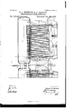
The accompanying drawings illustrate, by way of example, tubular steam-generators constructed according to this invention, Figures 1, la, 2, and 3 relating to the first type of a Normand steanrgenerator. Figs. l and 1a are a vertical longitudinal section of the steam-generator, taken along the axis thereof. Fig. 2 shows the said generator half in front elevation and half in cross -sectiong and Fig. 3 is a longitudinal section taken on the line X Y, Fig. 2, of the water-tubes.
A A are the front ends of the boilers, which are coupled together so as to form a single steam-generator.
B B are-the two side cylindrical vessels, into which the lower ends of the water-tubes open, while the upper ends of the said tubes from each lateral receiver terminate in the upper central reservoir C.
D D are bridges situated at the end of the grates.
E E E2 E3 indicate the return-water tubes situated outside the fire.
Hollow tie-rods F F F2 F3, containing water, connect the upper and lower collectors or receivers in the central part of the generator.
G G are inverted bridges under which the heated gases pass, as shown by the arrows,
before entering the smoke-box. A plate H divides the said smoke-box into two parts, and extending upwardly into the chimney separates the currents of gas from the two halves of the combined generator whatever be the difference of the pressures of the air or of the draft in the two heating-chambers. The chimney I is made common to the two united generators.
The upper central receiver O is preferably formed in two parts, as shown in Fig. l, communicating with each other by one or more tubes or pipes, so as to offer a small resistance to the passage of the gases and to reduce the Ico motion of the water in said upper receiver in a longitudinal direction. The said motion of the water can be further diminished both in the upper receiver and the lower receivers by means of horizontal screens or plates not Water-tight. The steam may be taken off either from one part of the two upper receivers, which constitute when connected one main upper receiver, or from each of the two parts. In the first case the junction-pipes, which form the communication for the steam between tlie two said parts ofthe receiver, must be of sufficient size to prevent the existence of any appreciable difference in pressure and level between the two said parts. The feedwater is preferably supplied to yeach of the generators, so as to secure a uniform production of steam.
The apparatus is preferably constructed to be readily separated when desired into two parts longitudinally, so as to facilitate its transport and erection.
WVhen there are two steam-generators of the new type in the width of the boat with receivers parallel to the longitudinal axis of the boat, the chimneys of the two generators are united according to this invention so as to form one. Figs. 4, 5, and 6 show two generators so arranged, Fig. 4 being a longitudinal elevation of generators of the first type; Fig. 5, a longitudinal velevation of generators of the second type-that is to say, generators in which the products of combustion are caused to return to the chimneys situated in the front portion of the said generators; and Fig. 6 is a transverse view common to both types of generators. The various parts of the said generators are similar to those which we have already described with reference to Figs. l, 2, and 3, and by reference to these figures their operation will be readily understood.
Vhen the vessel is sufficiently broad in its beam, generators constructed according to this invention may be arranged therein so that their longitudinal axis be at right angles to the axis of the vessel, the stoke holes being situated longitudinally on both sides the vessel. To facilitate such an installation which presents several advantages chiefly in connection with the service of the coal-bunkers and the arrangement of the chimneys, the
length of the said generators may be reduced by dispensing with the smoke-boxes separated by the plate H, as shown in Fig. l, and causing the heated products of combustion to leave laterally near the bridges D D. A passage for the said gases is made by opening the screen formed by the two rows or series of the outer longitudinal heating-tubes, the said passage starting from the said bridges and extending through a certain length toward the fronts of the generators. This arrangement is illustrated in Figs. 7 and 8 of the accompanying drawings, Fig. 7 showing in end View three generators arranged across the axis of the vessel, and Fig. 8 showing a side view of such generators. Figs. 9, 9, l0, and l1 illustrate, on a larger scale, one of these generators. Fig. 9 is a vertical longitudinal section of the said generator, taken along the axis thereof. Fig. lO shows the said generator half in front elevation and half yin cross-section; and Fig. ll isa longitudinal section taken on the line X V, Fig. l0, of the water-tubes.
The letters of reference have the same meaning as in Figs. l, 2, and 3.
This invention is not limited to the precise details described and illustrated inthe drawings, the various parts being capable of modiiication to suit the requirements of particular installations.
In a multitubular steam generator, the combination with two generators of like character provided with distinct furnaces and united to form a single combined generator, of an upper central receiver constructed in two like parts arranged end to end and a contracted neck or necks joining said receivers whereby communication between the sameis established, substantially as and for the purpose described.
In testimony-whereof we have signed this specification in the presence of two subscrib ing witnesses.
JACQUES AUGUSTIN NORMAND. PIERRE SIGAUDY.
Witnesses:
ALBERT DIQUET, V. L. MAIQUENT.
Publications (1)
| Publication Number | Publication Date |
|---|---|
| US548451A true US548451A (en) | 1895-10-22 |
Family
ID=2617194
Family Applications (1)
| Application Number | Title | Priority Date | Filing Date |
|---|---|---|---|
| US548451D Expired - Lifetime US548451A (en) | normand |
Country Status (1)
| Country | Link |
|---|---|
| US (1) | US548451A (en) |
-
0
- US US548451D patent/US548451A/en not_active Expired - Lifetime
Similar Documents
| Publication | Publication Date | Title |
|---|---|---|
| US548451A (en) | normand | |
| US439684A (en) | Sectional steam-boiler | |
| US610681A (en) | Steam-boiler | |
| US661529A (en) | Steam-boiler. | |
| US199139A (en) | Improvement in steam-boilers | |
| US261122A (en) | Cox and nathaniel w | |
| US113298A (en) | Improvement in tubular steam-boilers | |
| US599780A (en) | von grubinski | |
| US738964A (en) | Steam-generator. | |
| US626118A (en) | Dooooooooooooooo | |
| US200294A (en) | Improvement in sectional steam-generators | |
| US661530A (en) | Steam-boiler. | |
| US718525A (en) | Combination scotch and water-tube marine boiler. | |
| US711546A (en) | Water-tube boiler. | |
| US365801A (en) | De naeyer | |
| US476181A (en) | baird | |
| US249671A (en) | And stephen wilcox | |
| US839166A (en) | Steam-boiler. | |
| US405344A (en) | Steam-boiler | |
| US490303A (en) | Steam-boiler | |
| US719501A (en) | Steam-generator. | |
| US660751A (en) | Boiler. | |
| US809683A (en) | Steam generator and superheater. | |
| US670976A (en) | Water-tube boiler. | |
| US771657A (en) | Boiler. |