US5471122A - DC-motor bridge driver with end-of-braking detector - Google Patents
DC-motor bridge driver with end-of-braking detector Download PDFInfo
- Publication number
- US5471122A US5471122A US08/210,498 US21049893A US5471122A US 5471122 A US5471122 A US 5471122A US 21049893 A US21049893 A US 21049893A US 5471122 A US5471122 A US 5471122A
- Authority
- US
- United States
- Prior art keywords
- motor
- bridge
- braking
- output
- voltage
- Prior art date
- Legal status (The legal status is an assumption and is not a legal conclusion. Google has not performed a legal analysis and makes no representation as to the accuracy of the status listed.)
- Expired - Lifetime
Links
- 230000001052 transient effect Effects 0.000 abstract description 3
- 230000000694 effects Effects 0.000 abstract description 2
- 230000007704 transition Effects 0.000 abstract 1
- 239000004020 conductor Substances 0.000 description 4
- 238000001514 detection method Methods 0.000 description 2
- 230000005669 field effect Effects 0.000 description 2
- 239000004065 semiconductor Substances 0.000 description 2
- XUIMIQQOPSSXEZ-UHFFFAOYSA-N Silicon Chemical compound [Si] XUIMIQQOPSSXEZ-UHFFFAOYSA-N 0.000 description 1
- 230000003213 activating effect Effects 0.000 description 1
- 238000013459 approach Methods 0.000 description 1
- 230000002028 premature Effects 0.000 description 1
- 230000001681 protective effect Effects 0.000 description 1
- 230000011664 signaling Effects 0.000 description 1
- 229910052710 silicon Inorganic materials 0.000 description 1
- 239000010703 silicon Substances 0.000 description 1
Images


Classifications
-
- H—ELECTRICITY
- H02—GENERATION; CONVERSION OR DISTRIBUTION OF ELECTRIC POWER
- H02P—CONTROL OR REGULATION OF ELECTRIC MOTORS, ELECTRIC GENERATORS OR DYNAMO-ELECTRIC CONVERTERS; CONTROLLING TRANSFORMERS, REACTORS OR CHOKE COILS
- H02P7/00—Arrangements for regulating or controlling the speed or torque of electric DC motors
- H02P7/03—Arrangements for regulating or controlling the speed or torque of electric DC motors for controlling the direction of rotation of DC motors
- H02P7/04—Arrangements for regulating or controlling the speed or torque of electric DC motors for controlling the direction of rotation of DC motors by means of a H-bridge circuit
-
- Y—GENERAL TAGGING OF NEW TECHNOLOGICAL DEVELOPMENTS; GENERAL TAGGING OF CROSS-SECTIONAL TECHNOLOGIES SPANNING OVER SEVERAL SECTIONS OF THE IPC; TECHNICAL SUBJECTS COVERED BY FORMER USPC CROSS-REFERENCE ART COLLECTIONS [XRACs] AND DIGESTS
- Y10—TECHNICAL SUBJECTS COVERED BY FORMER USPC
- Y10S—TECHNICAL SUBJECTS COVERED BY FORMER USPC CROSS-REFERENCE ART COLLECTIONS [XRACs] AND DIGESTS
- Y10S388/00—Electricity: motor control systems
- Y10S388/907—Specific control circuit element or device
- Y10S388/921—Timer or time delay means
Definitions
- This invention relates to full-bridge drivers, for driving permanent magnet DC motors in either direction, that are capable of braking the motor when the motor direction is to be reversed, and more particularly to such a fully integratable bridge driver that additionally includes a detecting means which during braking relies upon the back-electromotive-force (b.e.m.f.) voltage of the motor for determining the time at which the motor has come to rest for signaling end-of-braking.
- b.e.m.f. back-electromotive-force
- Such transistor bridge drivers have included a braking means wherein at least one of the bridge transistors is utilized to "short" the motor, i.e. place a low impedance across the motor.
- a means for detecting the end of braking in such prior art drivers is rarely provided but in cases where such a feature is included, it is by employment of at least one braking-current sense resistor.
- the sense resistor is in series with the at least one bridge transistor used for "shorting" the motor.
- sense resistors are generally of very low value and difficult to integrate.
- sense resistors used in conjunction with integrated driver circuits of the prior art, are for these reasons commonly supplied as expensive discrete resistors, external to the integrated circuit, and thus become a source of a substantial increase in the cost of the driver circuit.
- This invention recognizes that in a reversing full-bridge driver utilizing one or more of the four bridge switches for braking by "shorting" the motor (through a low impedance circuit), the voltage across the motor during breaking first rises and then falls through zero voltage to an opposite polarity voltage before more slowly returning asymptotically toward zero again.
- the invention further recognizes that the asymptotic return of motor voltage to within a small range near zero voltage will be a practical measure of end-of-braking and that to use it requires means for ignoring the first brief fall of the motor voltage through zero.
- the invention is therefore to a permanent magnet DC-motor bridge-driver circuit of the kind having four transistor switches connected in bridge configuration and having two bridge output terminals to which a motor may be connected.
- a differential window comparator has a differential input connected to the bridge output terminals, for producing a binary signal at a first level only when the voltage across the two output terminals is within a small voltage range centered at about zero volts.
- a pulse-width filter circuit having an input connected to the window comparator is for producing an output signal of a particular binary level only when the comparator-produced binary signal remains at the first level for greater than a predetermined time. The effect of the pulse-width filter in combination with the window comparator is to ignore the first occurrence during braking of zero motor voltage.
- the small voltage range provided by the differential window comparator is preferably less than 50 millivolts.
- the pulse-width filter circuit is comprised of a signal-delay circuit having a delay time that is the above-mentioned predetermined time and the predetermined time is preferably less than 50 microseconds.
- the advantages of the end-of-detection feature of this invention include the dispensing with the need for sense resistors leading to the possibility for fully integrating the motor driver and the entire associated braking circuit.
- FIG. 1 shows a motor driver circuit of this invention.
- FIG. 2 shows a waveform of the motor current in the circuit of FIG. 1 during braking.
- FIG. 3 shows a waveform of the voltages V A and V B at the two motor terminals, respectively, in the circuit of FIG. 1 during braking.
- FIG. 4 shows a waveform of the motor voltage, V B -V A , at the two motor terminals in the circuit of FIG. 1 during braking.
- the time scales of the waveforms in FIGS. 2, 3 and 4 are the same.
- the voltage scales of FIGS. 3 and 4 are not the same.
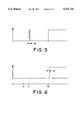
- FIG. 5 shows a waveform of the binary-signal voltage produced during braking at the output of the window comparator of FIG. 1.
- FIG. 6 shows a waveform of the binary-signal voltage produced during braking at the output of the pulse-width filter of FIG. 1.
- FIG. 7 shows a further developed motor driver circuit of this invention including the end-of-braking detector employed in FIG. 1.
- the DC-motor driver circuit of FIG. 1 includes a basic full-bridge driver that has four switches 11s, 12s, 13s and 14s that may be bipolar or field effect transistor switches. Shunting each of these switches are four clamp diodes 11d, 12d, 13d and 14d, respectively, which are used to clamp transient voltage spikes for protecting the semiconductor switches 11s, 12s, 13s and 14s respectively.
- the bridge 10 has two output terminals 16 and 18 to which a DC motor 20 is connected.
- the coasting motor 20 After time v the coasting motor 20 generates at the motor terminals a back electromotive force (b.e.m.f.) voltage causing the current Im through the motor to reverse and flow through closed switch 13s and diode 14d.
- This b.e.m.f. generated reverse motor current Im generates in turn a reverse, or braking, motor torque.
- the braking phase ends when the kinetic energy stored in the rotor mass is exhausted, and the b.e.m.f. and motor current Im become zero; and the motor has reached a full stop.
- Braking in both directions can be accomplished using either just the upper pair of switches 11s and 12s and diodes 11d and 12d, or just the lower pair of switches 13s and 14s and diodes 13d and 14d. If a full bridge driver has control circuits that automatically reverse the motor only after an end-of-braking signal is received, b.e.m.f. of the motor essentially never appears across and tends to break down the two bridge transistor switches which are not used for braking. Only in this special case, the protective diodes conventionally connected in parallel with the transistor switches which are not used for braking may be eliminated.
- the output of the bridge is the motor voltage V B -V A appearing across the bridge output terminals 16 and 18.
- the bridge output is connected to the input of a conventional differential window comparator 21.
- Comparator 21 is comprised of a pair of essentially identical resistors 22 and 24, and a pair of essentially identical current sources 26 and 28, which are series connected with the pair of resistors between a positive supply voltage +V and a negative supply voltage -V.
- the comparator 21 further includes an amplifier 31 having a positive input connected to resistor 22, and another amplifier 33 with a negative input connected to resistor 24.
- the positive and negative inputs respectively of amplifiers 31 and 33 are connected to each other and to the bridge output terminal 18.
- the junction between the resistors 22 and 24 is connected to the bridge output terminal 16.
- Comparator 21 also has an AND gate 36 with two inputs connected respectively to the outputs of the two amplifiers 31 and 33 so that when the voltage at the comparator input voltage lies within a small voltage range near zero, a high binary voltage is produced at the AND gate output, and otherwise a low binary voltage is produced as shown in FIG. 5.
- the output of the window comparator is connected to the input of a pulse-width filter 40 having a signal delay circuit 42 of fixed delay time t d and has an AND gate 44 with one input connected to the output of the delay circuit 42.
- the input of the delay circuit 42 is the input of the pulse-width filter circuit 40 which is also connected to another input of the AND gate 44.
- the output conductor 46 of the AND gate 44 is the output of the filter circuit 40 and of the entire end of braking circuit 47 in FIG. 1.
- the comparator 21 produces the narrow pulse of width t g .
- the width t g of this pulse is less than the delay time t d of the pulse-width filter 40, the binary voltage at output conductor 46 remains low. But at the end of motor braking action at time w when the motor voltage is again within the comparator window and is at near zero for a time exceeding t d , the output voltage level at conductor 46 goes high to signal the end of braking.
- the pulse width t g is approximately 50 microseconds.
- the delay time t d should be made great enough to insure that the output voltage at conductor 46 does not respond to the first passage through zero of the motor voltage to avoid a premature false indication of end of braking.
- the integrated-circuit DC-motor driver 48 of FIG. 7 includes the bridge and the end-of-braking detector of FIG. 1, and control logic 50 whereby the motor direction is controlled, and whereby feedback from the end-of-braking detector is provided to automatically brake the motor each time a signal to reverse motor direction is received, prior to the reversal of the motor direction.
- the motor 20 can be started in the forward direction, in the reverse direction or braked by means of the three momentary push buttons 51, 52 and 53, respectively.
- the symmetrical motor control logic 56 includes three 0R gates 57, 58 and 59, three set-reset latches 61, 62 and 63, four AND gates 67, 68, 69 and 70, and a bridge-logic block 72.
- the bridge logic block 72 turns on only bridge transistors 11 and 14 to cause the motor 20 to run in the forward direction when latch 61 is set and the binary signal level FW at the input of the bridge logic block 72 is high. Conversely when RV is high, only transistors 12 and 13 are turned on.
- the brake signal BK at the input of the bridge logic block 72 is high, a motor braking phase begins and when BK is low braking action stops.
- latch 62 When subsequently the push button 52 becomes activated, latch 62 will become set, while latch 61 becomes reset via OR gate 57.
- the pulse generated at the output of AND gate 67 will set, via OR gate 59 latch 63, via OR gate 59, so that via AND gates 69 and 70 a high FW or RV signal is blocked and prevented from activating the motor 20 in either forward or reverse directions, and the binary input signal BK to the bridge logic block 72 becomes high and will initiate a motor braking phase.
- the rotational inertia of the motor keeps it running, and the end-of-braking detector 74 produces a low binary output signal.
- the end-of-braking detector 74 produces a high binary output that resets latch 63 and allowing at the same time the binary reverse signal RV to start the motor in the reverse direction.
Abstract
Description
Claims (7)
Priority Applications (1)
| Application Number | Priority Date | Filing Date | Title |
|---|---|---|---|
| US08/210,498 US5471122A (en) | 1993-09-14 | 1993-09-14 | DC-motor bridge driver with end-of-braking detector |
Applications Claiming Priority (1)
| Application Number | Priority Date | Filing Date | Title |
|---|---|---|---|
| US08/210,498 US5471122A (en) | 1993-09-14 | 1993-09-14 | DC-motor bridge driver with end-of-braking detector |
Publications (1)
| Publication Number | Publication Date |
|---|---|
| US5471122A true US5471122A (en) | 1995-11-28 |
Family
ID=22783145
Family Applications (1)
| Application Number | Title | Priority Date | Filing Date |
|---|---|---|---|
| US08/210,498 Expired - Lifetime US5471122A (en) | 1993-09-14 | 1993-09-14 | DC-motor bridge driver with end-of-braking detector |
Country Status (1)
| Country | Link |
|---|---|
| US (1) | US5471122A (en) |
Cited By (8)
| Publication number | Priority date | Publication date | Assignee | Title |
|---|---|---|---|---|
| US6198315B1 (en) * | 1998-01-12 | 2001-03-06 | Mitsubishi Denki Kabushiki Kaisha | Current detection circuit |
| US6392373B1 (en) | 2000-12-06 | 2002-05-21 | Milwaukee Electric Tool Corporation | Automatic reverse motor controller |
| US20040183490A1 (en) * | 2003-01-27 | 2004-09-23 | Rohm Co., Ltd. | Electric motor control device |
| US20070069672A1 (en) * | 2000-12-06 | 2007-03-29 | Glasgow Kevin L | Power tool and motor controller |
| US20100007381A1 (en) * | 2008-07-10 | 2010-01-14 | Sanyo Electric Co., Ltd. | Drive signal output circuit and multi-chip package |
| US20130207647A1 (en) * | 2010-07-22 | 2013-08-15 | Robert Bosch Gmbh | Method and device for the sensor-free position determination of an electronically commutated electric machine |
| WO2017179061A1 (en) * | 2016-04-15 | 2017-10-19 | Rewalk Robotics Ltd. | Apparatus and systems for controlled collapse of an exoskeleton |
| US11374513B2 (en) | 2019-01-23 | 2022-06-28 | Allegro Microsystems, Llc | Motor control circuit with degauss filter |
Citations (13)
| Publication number | Priority date | Publication date | Assignee | Title |
|---|---|---|---|---|
| US3813591A (en) * | 1973-03-06 | 1974-05-28 | Gen Electric | Dc motor speed control circuit |
| US3969661A (en) * | 1973-08-20 | 1976-07-13 | Hitachi, Ltd. | Motor control apparatus |
| US4270164A (en) * | 1979-02-28 | 1981-05-26 | Contraves Goerz Corporation | Short circuit protection for switching type power processors |
| US4493015A (en) * | 1981-12-21 | 1985-01-08 | Siemens Aktiengesellschaft | Circuit arrangement for determining the load current in a reversible d-c controller or chopper |
| US4511835A (en) * | 1982-12-23 | 1985-04-16 | Borg-Warner Corporation | Voltage-controlled, inverter-motor system |
| US4562386A (en) * | 1984-01-26 | 1985-12-31 | Performance Controls Company | Current sense demodulator |
| US4562387A (en) * | 1984-11-26 | 1985-12-31 | General Motors Corporation | Vehicle power window control |
| US4562393A (en) * | 1983-09-29 | 1985-12-31 | Kollmorgen Technologies Corporation | Modulation scheme for PWM-type amplifiers or motors |
| US4628232A (en) * | 1985-05-28 | 1986-12-09 | Kb Electronics Inc. | Anti-plug reversing module |
| US4677356A (en) * | 1984-12-27 | 1987-06-30 | Haruhiro Tsuneda | DC motor drive control device |
| US4680513A (en) * | 1986-08-11 | 1987-07-14 | Harbor Branch Oceanographic Institute Inc. | Electric motor reversing control devices |
| US4897882A (en) * | 1989-03-10 | 1990-01-30 | Caterpillar Industrial Inc. | Motor control apparatus and method |
| US5032780A (en) * | 1989-09-29 | 1991-07-16 | Sgs-Thomson Microelectronics, Inc. | Programmable stepper motor controller |
-
1993
- 1993-09-14 US US08/210,498 patent/US5471122A/en not_active Expired - Lifetime
Patent Citations (13)
| Publication number | Priority date | Publication date | Assignee | Title |
|---|---|---|---|---|
| US3813591A (en) * | 1973-03-06 | 1974-05-28 | Gen Electric | Dc motor speed control circuit |
| US3969661A (en) * | 1973-08-20 | 1976-07-13 | Hitachi, Ltd. | Motor control apparatus |
| US4270164A (en) * | 1979-02-28 | 1981-05-26 | Contraves Goerz Corporation | Short circuit protection for switching type power processors |
| US4493015A (en) * | 1981-12-21 | 1985-01-08 | Siemens Aktiengesellschaft | Circuit arrangement for determining the load current in a reversible d-c controller or chopper |
| US4511835A (en) * | 1982-12-23 | 1985-04-16 | Borg-Warner Corporation | Voltage-controlled, inverter-motor system |
| US4562393A (en) * | 1983-09-29 | 1985-12-31 | Kollmorgen Technologies Corporation | Modulation scheme for PWM-type amplifiers or motors |
| US4562386A (en) * | 1984-01-26 | 1985-12-31 | Performance Controls Company | Current sense demodulator |
| US4562387A (en) * | 1984-11-26 | 1985-12-31 | General Motors Corporation | Vehicle power window control |
| US4677356A (en) * | 1984-12-27 | 1987-06-30 | Haruhiro Tsuneda | DC motor drive control device |
| US4628232A (en) * | 1985-05-28 | 1986-12-09 | Kb Electronics Inc. | Anti-plug reversing module |
| US4680513A (en) * | 1986-08-11 | 1987-07-14 | Harbor Branch Oceanographic Institute Inc. | Electric motor reversing control devices |
| US4897882A (en) * | 1989-03-10 | 1990-01-30 | Caterpillar Industrial Inc. | Motor control apparatus and method |
| US5032780A (en) * | 1989-09-29 | 1991-07-16 | Sgs-Thomson Microelectronics, Inc. | Programmable stepper motor controller |
Cited By (19)
| Publication number | Priority date | Publication date | Assignee | Title |
|---|---|---|---|---|
| US6198315B1 (en) * | 1998-01-12 | 2001-03-06 | Mitsubishi Denki Kabushiki Kaisha | Current detection circuit |
| US20080047974A1 (en) * | 2000-12-06 | 2008-02-28 | Glasgow Kevin L | Power tool and motor controller |
| US6392373B1 (en) | 2000-12-06 | 2002-05-21 | Milwaukee Electric Tool Corporation | Automatic reverse motor controller |
| US7420341B2 (en) | 2000-12-06 | 2008-09-02 | Milwaukee Electric Tool Corporation | Power tool and motor controller |
| US6823134B2 (en) | 2000-12-06 | 2004-11-23 | Milwaukee Electric Tool Corporation | Automatic reverse motor controller |
| US20020136541A1 (en) * | 2000-12-06 | 2002-09-26 | Milwaukee Electric Tool Corporation | Automatic reverse motor controller |
| US20070069672A1 (en) * | 2000-12-06 | 2007-03-29 | Glasgow Kevin L | Power tool and motor controller |
| US7282880B2 (en) | 2000-12-06 | 2007-10-16 | Milwaukee Electric Tool Corporation | Power tool and motor controller |
| US20040183490A1 (en) * | 2003-01-27 | 2004-09-23 | Rohm Co., Ltd. | Electric motor control device |
| US6922032B2 (en) * | 2003-01-27 | 2005-07-26 | Rohm Co., Ltd. | Electric motor control device |
| US7928771B2 (en) * | 2008-07-10 | 2011-04-19 | Sanyo Electric Co., Ltd. | Drive signal output circuit and multi-chip package |
| CN101626218B (en) * | 2008-07-10 | 2012-07-25 | 三洋电机株式会社 | Driving signal output circuit and multi chip package |
| US20100007381A1 (en) * | 2008-07-10 | 2010-01-14 | Sanyo Electric Co., Ltd. | Drive signal output circuit and multi-chip package |
| US20130207647A1 (en) * | 2010-07-22 | 2013-08-15 | Robert Bosch Gmbh | Method and device for the sensor-free position determination of an electronically commutated electric machine |
| US10101146B2 (en) * | 2010-07-22 | 2018-10-16 | Robert Bosch Gmbh | Method and device for the sensor-free position determination of an electronically commutated electric machine |
| WO2017179061A1 (en) * | 2016-04-15 | 2017-10-19 | Rewalk Robotics Ltd. | Apparatus and systems for controlled collapse of an exoskeleton |
| CN109069338A (en) * | 2016-04-15 | 2018-12-21 | 人行道机器人有限公司 | The device and system of controlled collapse for ectoskeleton |
| US10980698B2 (en) | 2016-04-15 | 2021-04-20 | Rewalk Robotics Ltd. | Apparatus and systems for controlled collapse of an exoskeleton |
| US11374513B2 (en) | 2019-01-23 | 2022-06-28 | Allegro Microsystems, Llc | Motor control circuit with degauss filter |
Similar Documents
| Publication | Publication Date | Title |
|---|---|---|
| US5457364A (en) | Bridge motor driver with short-circuit protection and motor-current limiting feature | |
| US6335608B1 (en) | Fault protection circuitry for motor controllers | |
| US4725765A (en) | Method and apparatus for the protection of D.C. motors under stalled conditions | |
| US4901366A (en) | Circuit arrangement for the timed control of semiconductor switches | |
| US4496886A (en) | Three state driver for inductive loads | |
| US4731570A (en) | Electrical drive circuit for a variable-speed switched reluctance motor | |
| CN109599845B (en) | Protection circuit, upper bridge driving chip and IPM module | |
| US5471122A (en) | DC-motor bridge driver with end-of-braking detector | |
| EP0392831A3 (en) | Power transistor drive circuit with improved short circuit protection | |
| US4314325A (en) | Method and circuit for pulse-width control of a bilateral direct current control element | |
| JPH0923664A (en) | Inverter device | |
| EP0639005A1 (en) | Fast turn-off circuit for solid-state relays or the like | |
| US7719223B2 (en) | Switching node based sensorless motor control for PM motor | |
| US4651252A (en) | Transistor fault tolerance method and apparatus | |
| US4972129A (en) | Passive seat belt apparatus | |
| GB2029136A (en) | Speed control circuit for a direct current motor having armature control | |
| US4011492A (en) | Chopper motor controller having pulse-by-pulse sensing of plugging | |
| JPS5826572A (en) | Controlling device | |
| JPH07297698A (en) | On/off control circuit for semiconductor element | |
| WO1997050162A1 (en) | Motor driving apparatus | |
| US4477758A (en) | Stepping motor overcurrent detection and protection device | |
| US6252436B1 (en) | Method and arrangement for determining state information of power semiconductor | |
| JPH10217763A (en) | Motor control device for switching mechanism | |
| JP3596415B2 (en) | Inductive load drive circuit | |
| JPH08265121A (en) | Overcurrent limit circuit for power transistor |
Legal Events
| Date | Code | Title | Description |
|---|---|---|---|
| AS | Assignment |
Owner name: ALLEGRO MICROSYSTEMS, INC., MASSACHUSETTS Free format text: ASSIGNMENT OF ASSIGNORS INTEREST;ASSIGNORS:BILOTTI, ALBERTO;TALLARICO, JOSE LUIS;REEL/FRAME:006863/0116 Effective date: 19940131 |
|
| STCF | Information on status: patent grant |
Free format text: PATENTED CASE |
|
| FPAY | Fee payment |
Year of fee payment: 4 |
|
| FPAY | Fee payment |
Year of fee payment: 8 |
|
| FPAY | Fee payment |
Year of fee payment: 12 |
|
| AS | Assignment |
Owner name: ALLEGRO MICROSYSTEMS, LLC, MASSACHUSETTS Free format text: CONVERSION AND NAME CHANGE;ASSIGNOR:ALLEGRO MICROSYSTEMS, INC.;REEL/FRAME:030426/0178 Effective date: 20130321 |
|
| AS | Assignment |
Owner name: CREDIT SUISSE AG, CAYMAN ISLANDS BRANCH, AS COLLATERAL AGENT, NEW YORK Free format text: PATENT SECURITY AGREEMENT;ASSIGNOR:ALLEGRO MICROSYSTEMS, LLC;REEL/FRAME:053957/0874 Effective date: 20200930 Owner name: MIZUHO BANK LTD., AS COLLATERAL AGENT, NEW YORK Free format text: PATENT SECURITY AGREEMENT;ASSIGNOR:ALLEGRO MICROSYSTEMS, LLC;REEL/FRAME:053957/0620 Effective date: 20200930 |
|
| AS | Assignment |
Owner name: ALLEGRO MICROSYSTEMS, LLC, NEW HAMPSHIRE Free format text: RELEASE OF SECURITY INTEREST IN PATENTS (R/F 053957/0620);ASSIGNOR:MIZUHO BANK, LTD., AS COLLATERAL AGENT;REEL/FRAME:064068/0360 Effective date: 20230621 |
|
| AS | Assignment |
Owner name: ALLEGRO MICROSYSTEMS, LLC, NEW HAMPSHIRE Free format text: RELEASE OF SECURITY INTEREST IN PATENTS AT REEL 053957/FRAME 0874;ASSIGNOR:CREDIT SUISSE AG, CAYMAN ISLANDS BRANCH, AS COLLATERAL AGENT;REEL/FRAME:065420/0572 Effective date: 20231031 |