US546565A - Tobacco-granulating machine - Google Patents
Tobacco-granulating machine Download PDFInfo
- Publication number
- US546565A US546565A US546565DA US546565A US 546565 A US546565 A US 546565A US 546565D A US546565D A US 546565DA US 546565 A US546565 A US 546565A
- Authority
- US
- United States
- Prior art keywords
- tobacco
- bar
- cylinder
- cutter
- cutting
- Prior art date
- Legal status (The legal status is an assumption and is not a legal conclusion. Google has not performed a legal analysis and makes no representation as to the accuracy of the status listed.)
- Expired - Lifetime
Links
- 241000208125 Nicotiana Species 0.000 description 68
- 235000002637 Nicotiana tabacum Nutrition 0.000 description 68
- 241000681094 Zingel asper Species 0.000 description 18
- 239000000428 dust Substances 0.000 description 6
- 230000000284 resting Effects 0.000 description 6
- 238000010276 construction Methods 0.000 description 4
- 239000002184 metal Substances 0.000 description 4
- 210000002370 ICC Anatomy 0.000 description 2
- 238000006243 chemical reaction Methods 0.000 description 2
- 238000001035 drying Methods 0.000 description 2
- 239000004744 fabric Substances 0.000 description 2
- 239000000835 fiber Substances 0.000 description 2
- 239000008187 granular material Substances 0.000 description 2
- 238000005469 granulation Methods 0.000 description 2
- 230000003179 granulation Effects 0.000 description 2
- 210000001699 lower leg Anatomy 0.000 description 2
- 238000000034 method Methods 0.000 description 2
- 238000000926 separation method Methods 0.000 description 2
- 239000007787 solid Substances 0.000 description 2
- 239000002699 waste material Substances 0.000 description 2
Images


Classifications
-
- B—PERFORMING OPERATIONS; TRANSPORTING
- B02—CRUSHING, PULVERISING, OR DISINTEGRATING; PREPARATORY TREATMENT OF GRAIN FOR MILLING
- B02C—CRUSHING, PULVERISING, OR DISINTEGRATING IN GENERAL; MILLING GRAIN
- B02C7/00—Crushing or disintegrating by disc mills
- B02C7/11—Details
- B02C7/14—Adjusting, applying pressure to, or controlling distance between, discs
-
- Y—GENERAL TAGGING OF NEW TECHNOLOGICAL DEVELOPMENTS; GENERAL TAGGING OF CROSS-SECTIONAL TECHNOLOGIES SPANNING OVER SEVERAL SECTIONS OF THE IPC; TECHNICAL SUBJECTS COVERED BY FORMER USPC CROSS-REFERENCE ART COLLECTIONS [XRACs] AND DIGESTS
- Y10—TECHNICAL SUBJECTS COVERED BY FORMER USPC
- Y10S—TECHNICAL SUBJECTS COVERED BY FORMER USPC CROSS-REFERENCE ART COLLECTIONS [XRACs] AND DIGESTS
- Y10S83/00—Cutting
- Y10S83/906—Chip making
-
- Y—GENERAL TAGGING OF NEW TECHNOLOGICAL DEVELOPMENTS; GENERAL TAGGING OF CROSS-SECTIONAL TECHNOLOGIES SPANNING OVER SEVERAL SECTIONS OF THE IPC; TECHNICAL SUBJECTS COVERED BY FORMER USPC CROSS-REFERENCE ART COLLECTIONS [XRACs] AND DIGESTS
- Y10—TECHNICAL SUBJECTS COVERED BY FORMER USPC
- Y10T—TECHNICAL SUBJECTS COVERED BY FORMER US CLASSIFICATION
- Y10T83/00—Cutting
- Y10T83/444—Tool engages work during dwell of intermittent workfeed
- Y10T83/447—Plural tools successively actuated at same station
- Y10T83/4473—During one dwell period
-
- Y—GENERAL TAGGING OF NEW TECHNOLOGICAL DEVELOPMENTS; GENERAL TAGGING OF CROSS-SECTIONAL TECHNOLOGIES SPANNING OVER SEVERAL SECTIONS OF THE IPC; TECHNICAL SUBJECTS COVERED BY FORMER USPC CROSS-REFERENCE ART COLLECTIONS [XRACs] AND DIGESTS
- Y10—TECHNICAL SUBJECTS COVERED BY FORMER USPC
- Y10T—TECHNICAL SUBJECTS COVERED BY FORMER US CLASSIFICATION
- Y10T83/00—Cutting
- Y10T83/444—Tool engages work during dwell of intermittent workfeed
- Y10T83/4645—With means to clamp work during dwell
-
- Y—GENERAL TAGGING OF NEW TECHNOLOGICAL DEVELOPMENTS; GENERAL TAGGING OF CROSS-SECTIONAL TECHNOLOGIES SPANNING OVER SEVERAL SECTIONS OF THE IPC; TECHNICAL SUBJECTS COVERED BY FORMER USPC CROSS-REFERENCE ART COLLECTIONS [XRACs] AND DIGESTS
- Y10—TECHNICAL SUBJECTS COVERED BY FORMER USPC
- Y10T—TECHNICAL SUBJECTS COVERED BY FORMER US CLASSIFICATION
- Y10T83/00—Cutting
- Y10T83/647—With means to convey work relative to tool station
- Y10T83/6579—With means to press work to work-carrier
-
- Y—GENERAL TAGGING OF NEW TECHNOLOGICAL DEVELOPMENTS; GENERAL TAGGING OF CROSS-SECTIONAL TECHNOLOGIES SPANNING OVER SEVERAL SECTIONS OF THE IPC; TECHNICAL SUBJECTS COVERED BY FORMER USPC CROSS-REFERENCE ART COLLECTIONS [XRACs] AND DIGESTS
- Y10—TECHNICAL SUBJECTS COVERED BY FORMER USPC
- Y10T—TECHNICAL SUBJECTS COVERED BY FORMER US CLASSIFICATION
- Y10T83/00—Cutting
- Y10T83/869—Means to drive or to guide tool
- Y10T83/8748—Tool displaceable to inactive position [e.g., for work loading]
Definitions
- My invention relates to tobacco-granulating machines, and has for its objects to improve the construction and capacityof such machines, avoid waste and loss of tobacco by enabling it to be worked more economically and with less making of dust, and to largely increase the product within a given time by reason of the greater speed with which the tobacco may be handled.
- the invention consists in features of construction and novel combinations of parts in a tobacco cutting and granulating machine, as hereinafter more particularly described and claimed.
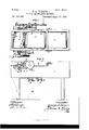
- Figure 1 is a plan of my improved tobacco-granulating machine.
- Figs. 2 and 3 are elevations from opposite sides.
- Fig. 4 is a vertical longitudinal section of the machine.
- Fig. 5 is a view of the detachable top framesection.
- FIG. 8 is a view of one of the splitting-knives detached.
- Fig. 10 is a view of the rotary tended diagonally about one-fourth around this cylinder 3 and from end to end thereof is set a series of tobacco-splitters or splittingknives 4, that are each about one inch and a half in length, say, one-eighth of an inch thick at the base or attaching portion, and
- the knives 4 are arranged parallel with each other them in the cylinder 3, and they may be detachably secured therein by any suitable means, as by a metal strip 5screwed to the Figs.'6 and 7 are views of the out cylinder and bearing on the ends of the knife shanks in such manner as to hold the knives in place.
- the purpose of the series of splitters or knives 4- is to split into longitudinal strips the tobacco fed to the cylinder 3, as hereinafter explained. At. a point about or very nearly opposite the diagonally-arranged series of splitters 4 there is secured to the cylinder 3 adiagonally-placed cutting-blade 6 for cutting the strips of tobacco transversely.
- the cutting-blade 6 is extended diagonally about one-fourth around the cylinder and from end to end.
- the cutting-edge of the blade 6 is beveled underneath, and may project beyond the face or periphery of the cylinderabout one-eighth of an inch.
- Each splitting-knife 4 may project fully one-fourth of an inch beyond the cylinder-face.
- a straight-edged cutter-bar 7 to co-act with the cutting-blade 6, that is carried by the cylinder.
- the cutter-bar 7 is arranged to have a forward and back movement in guideslots 8, provided in the sides of the machinefra'me.
- studs 9 for connection with eccentric rods 10,
- the rear roller 16 may be provided with means for adjusting the tension of the belt or apron 12, such as rods 17, attached at one end to the journal-bearings of the rollershaft and their other ends resting in sockets formed lengthwise in the frame 1, the said rods being each threaded a sufficient distance intermediate their ends and their threaded portions engaged in screw-taps or nuts 18, loosely supported by the frame 1 in such manner that by turning said nuts the rods engaged therewith will be moved longitudinally to adjust the connected roller 16 forward or back and thereby give any required tension to the endless belt or apron.
- means for adjusting the tension of the belt or apron 12 such as rods 17, attached at one end to the journal-bearings of the rollershaft and their other ends resting in sockets formed lengthwise in the frame 1, the said rods being each threaded a sufficient distance intermediate their ends and their threaded portions engaged in screw-taps or nuts 18, loosely supported by the frame 1 in such manner that by turning said nuts the rods engaged therewith will be moved
- the lower belt or apron 12 is actuated from the roller 14, the shaft of which has secured to one end a ratchet-wheel 19, with its teeth disposed in such direction as to permit the application of power from the rear for causing the upper face of the lower belt 12 to be moved intermittently toward the cutting-cylinder.
- a pawl-lever 20 carrying on its upper end a pawl 21, engaged with the upper rear portion of the ratchet-wheel 19, and the lower end of the lever 20 is connected by a rod or eccentric strap 22 with an eccentric 23 on the shaft 2 of the cutting-cylinder.
- the upper endless belt or apron 13 is carried on rollers 21 and 25, journaled transversely in a removable framesection 26, mounted on the upper portion of the main frame.
- a removable framesection 26 When the upper frame-section 26 is in position, the forward roller 2st of the upper belt 13 will occupy position above the forward roller 11 of the lower belt 12 and the rear upper roller 25 may occupy position above the intermediate lower roller 15, with which the lower endless belt or apron 12 is preferably provided.
- the shaft of the front upper roller 21 has secured to one end a ratchet-wheel 27, having its teeth disposed in such direction as to be engaged by a pawl 28, carried by a lever 29, mounted on and actuated from an eccentric 30 on the shaft 2 of the cutting-cylinder in such manner as to cause an intermittent movement of the lower face of the upper endless belt or apron 13 toward said cylinder.
- the top frame-section 26 is detachably secured to the main frame 1 by means of four bolts 31, extended vertically through both sections of the frame, there being two bolts on each side.
- the upper ends of the bolts 31 are headed, and their lower ends have nuts 32 engaged therewith and arranged as bearings for strong spiral springs 33, through which the top frame-section 26 and belt 13, mounted therein, will be caused to press the tobacco down as it is fed toward the cutting mechanism.
- hooks or catches 3st may be arranged to engage the ends of the top sec tion 26 with the main frame.
- a presser-baror presser-foot 35 having its ends supported by and secured to angle-bars 36, that are adj ustably connected to the rearward ends of a pair of levers 37, arranged on opposite sides of the frame 1 and having their forward ends pivoted thereto.
- Springs 38 are mounted on the frame 1 and arranged to force the presser-bar 35 down onto the tobacco resting above the cutter-bar 7 when the latter is in its forward position.
- the levers 37 extend above and bear upon cams 39, carried on the shaft 2 of the cuttingoylinder 3 and arranged to act on the levers 37, so as to cause them to lift the prosser-bar 35 at proper intervals.
- the leaf-tobacco to be granulated is untied and spread out upon the exposed surface of the lower traveling band or apron 12 and is carried by and between the two feed-bands 12 and 13 to the cutter-bar 7 and beneath the raised presser-bar 35, which works above the top of the cutter-bar 7 and holds the tobacco down after it has been fed forward until the splitters 4 pass down through the tobacco, splitting it longitudinally one-eighth of an inch deep and, say, at intervals one-eighth of an inch apart.
- the cutter-bar 7 then moves forward, and the tobacco is held down thereon by the presser-bar 35 until after the cuttingblade 6 comes around and cuts off smoothly and cleanly the ends of the split tobacco in lengths of,say, one-eighth of an inch, and the tobacco being thus out into uniform squares drops down between the cylinder 3 and cutter-bar 7 and into any suitable receptacle.
- the ratchet-wheels 19 and 27 may each have eighty teeth or notches one-half inch apart, and each revolution of the cylinder 3 moves the ratchet-wheels one notch.
- the rollers to which the ratchet-wheels are connected will be about ten inches in circumference, so that eighty cuts of one-eighth inch each will be made during each revolution of these ratchetwheels.
- Power may be applied to the cylinder-shaft 2 in any convenient or suitable manner, as by a spur-gear 40, mounted thereon and having, say, twenty teeth or cogs meshing with a larger spur-gear 41, having, say, one hundred teeth, and mounted on a spindle secured to the main frame of the machine.
- the gear 41 may be provided with a crank for applying handpower, or instead of this gearing any other means may be provided for giving motion to the machine.
- a balance or fly'wheel 42 may be placed on one end of the cylinder-shaft.
- the geared wheels may be replaced by a pulley placed on the cylinder-shaft 2 and bolted to the band-Wheel of an engine.
- the tobacco can with this machine be readily granulated or cut into squares of one-eighth inch while in good tough handling orderandin such manner as to avoid the loss and expense of drying, with consequent conversion of a large part of ICC the tobacco'into dust, it being possible to save at least ten per cent.
- the diagonally-arranged series of splittingknives 4 should project about one-fourth of an inch from the periphery of the cutting-cylinder, so as to properly split the tobacco, and in order that the cutter-bar 7 may be placed close to the cylinder 3 in position for properly holdin g the tobacco to the action of the diagonallyarranged transversely cutting-blade 6, and yet avoid contact with the splitting-knives 4 that travel in a larger circle than the blade 6, it is necessary to give the said cutter-bar 7 an automatic adjustment, as before explained.
- the presser-bar 35 drops onto the tobacco over the cutter-bar 7 and the latter slides backward under the action of its connected eccentric mechanism, thereby enabling the splitting-knives 4 to pass down through the tobacco without touching the cutter-bar, the presser-bar 35 meantime being still on the tobacco, holding it in its place, until the eccentric movement again brings the cutter-bar 7 to the front under the tobacco and within about one-eighth inch of the split-tobacco ends.
- the diagonally-arranged cutting-blade 6, carried by the cylinder 3, now comes into proper position and shaves off the projecting ends of the tobacco strips with a shear cut along the entire length of the cutter-bar 7, from which the tobacco drops, out into square pieces one-eighth of an inch each way.
- the presser-bar 35 now rises to receive the feed again, and the operations described are repeated.
- the cut or granulated tobacco may be received in a chute 43, leading to one of the open ends of a rotary screen-cylinder 44 placed on a lower floor of the building.
- the rotary screen 44 is to be open at both ends and consists of a suitable framework having its pe-v riphery composed of wire-cloth in different divisions of varying mesh.
- One division or section 45 of the rotary screen 44 should consist of wire in meshes of twenty-five or thirty to the square inch for separation of any fine dust mingled with the tobacco.
- the next section 46 should be woven with small wire three strands close together and then a space of half an inch, and so on alternately throughout the length of the section, which is filled in longitudinally with wire strands one-twentieth of an inch apart.
- the third and last section 47 of the rotary screen may consist of six meshes to the inch each way.
- the meshing is such that the granulated leaf-tobacco will pass through edgewise, while the stems, being more-bulky, are carried farther along and may escape through the last section of the screen.
- a solid and rigidly-supported bed-plate 48 secured by bracket-arms 49 to the inner sides of the machine-frame.
- a stationary plate 50 of thin metal, arranged above the top of the movable cutter-bar 7 to prevent the tobacco from getting behind and choking the space between the lower feed-belt and said automatically-adjustable cutter-bar.
- a sufficient space is provided between the upper plate 50 and bed-plate 48 for the cutter-bar 7 to move automatically and with ease.
- the plates 48 and 50 are justoutside the circuit of the splitting-knives 4, and when the splitting takes place the tobacco is resting on the top plate 50 with the cutter-bar 7 under it and on a line with the front edges of both the top plate and bed-plate. Before the cutting-blade 6 comes around the cutter-bar 7- moves forward about one-eighth of an inch, and as the said blade passes the cutter-bar the tobacco is cut off.
- I claim as my invention is 1.
- a tobacco-cutting or granulating machine the combination with a rotary cylinder provided with a cutting blade and with a series of splitting knives moving in a larger circle than said cutting blade and projecting beyond the same, of an automatically adjustable cutter-bar supported adjacent to said cylinder for joint operation with the said cutting blade and knives, substantially as described.
- a rotary cylinder provided with a cutting-blade and with a series of splitting knives moving in a larger circle than said cutting-blade and projecting beyond the same, of a movable cutter-bar supported adjacent to said cylinder for joint operation with the cutting blade carried thereon, and eccentric mechanism connecting said cutter-bar with the shaft of the said cylinder to automatically move said bar to and from the cylinder and out of the path of the splitting knives, substantially as described.
- a tobacco-cutting or granulating machine the combination with a rotary cylinder provided with a cutting-blade and with a series of splitting knives, of an automatically movable cutter-bar supported adjacent to the said cylinder, eccentric mechanism connect- IIO vided with a cutting-blade and with a series of splitting knives, an automatically adj ustable cutter-bar actuated from the cylindershaft, and a yielding presser-bar provided with cam-actuated lifting mechanism, of two endless feed bands arranged one above the other and mounted on the rollers, ratchetwheels secured to rollers of said feed bands, and pawl mechanism engaged with said ratchet wheels and actuated from the cyli ndershaft, substantially as described.
- a frame having a cutting-cylinder mounted in one end, a cutter-bar supported on said frame and automatically adjustable from the cylinder shaft, a presser-bar arranged above the cutter-bar, means for actuating said presser-bar, a lower endless feed band mounted in the main frame and actuated from the cylinder-shaft, an upper detachable frame section having an upper endless feed band mounted therein and actuated from the cylinder shaft, and spring pressed rods or bolts extended vertically through the main frame and upper frame section and adapted to cause the upper feed band to press down on the tobacco, substantially as described.
- a rotary cylinder provided with a cutting-blade and with a series of splitting knives moving in a larger circle than said cutting blade and projecting beyond the same
- an automatically adjustable cutter-bar supported adjacent to said cylinder for joint operation with the cutting-blade and knives carried thereon, means for auto matically adjusting the said cutter-bar, and a stationary plate supported above said outter-bar and outside the circuit of the splitting knives carried by the cylinder, substantially as described.
- a rotary cylinder provided with a cutting-blade and with a series of splitting knives
- an automatically adjustable cutter-bar arranged for joint operation with the cutting-blade and knives carried on the rotary cylinder
- a stationary bedplate below said movable cutter-bar
- a stationary top plate above the movable cutterbar
- said bed plate and top plate being outside the circuit of the splitting knives carried by the cylinder
- means for automatically moving the adjustable cutter-bar to and from the cylinder and out of the path of the splitting knives substantially as described.
- a rotary cylinder provided with a cutting-blade and a series of splitting knives, an automatically adjustable cutter-bar for joint operation with the cutting-blade and knives, means for automatically adjusting said cutter-bar, a stationary plate above said cutter-bar, a yielding presser-bar above said plate, and the endless feed bands, substantially as described.
Landscapes
- Engineering & Computer Science (AREA)
- Food Science & Technology (AREA)
- Manufacturing Of Cigar And Cigarette Tobacco (AREA)
Description
(N0 M'odIJ) 3 Sheets-Sheet 1.
' G. A. TURNER.
TOBACCO GRANULATING MACHINE.
No. 546,565. Patented Sept. 1'7, 1895,.
wfia dmsot zzyezzfor M ewyeul 12127267.
ANDREW B.GRANAM.PHOTOUMQWASHINGTDMDL in the partly-spiral groove or seat formed for- UNrnn 'rArns Enron.
GEORGE A. TURNER, OF ROANOKE, VIRGINIA.
.TOBACCO-GRANULATING MACHINE.
SPECIFICATION forming part of Letters Patent No. 546,565, dated September 17, 1895.
Application filed May 18. 1895. fierial No. 549,801. (No model.)
To all whom it may concerm Be it known that I, GEORGE A. TURNER, a citizen of the United States, residing at Roanoke, in the county of Roanoke and State of Virginia, have invented new and useful Improvements in Tobacco Granulating Machines, of which the following is a specification.
My invention relates to tobacco-granulating machines, and has for its objects to improve the construction and capacityof such machines, avoid waste and loss of tobacco by enabling it to be worked more economically and with less making of dust, and to largely increase the product within a given time by reason of the greater speed with which the tobacco may be handled.
The invention consists in features of construction and novel combinations of parts in a tobacco cutting and granulating machine, as hereinafter more particularly described and claimed.
In the annexed drawings, illustrating the invention, Figure 1 is a plan of my improved tobacco-granulating machine. Figs. 2 and 3 are elevations from opposite sides. Fig. 4 is a vertical longitudinal section of the machine. Fig. 5 is a view of the detachable top framesection.
ting-cylinder and its knives. Fig. 8 is a view of one of the splitting-knives detached. Fig.
9 is a detail View of the feed and presser mechanism. Fig. 10 is a view of the rotary tended diagonally about one-fourth around this cylinder 3 and from end to end thereof is set a series of tobacco-splitters or splittingknives 4, that are each about one inch and a half in length, say, one-eighth of an inch thick at the base or attaching portion, and
for the remainder of their width they are each hollow-ground to an edge, as shown. The knives 4 are arranged parallel with each other them in the cylinder 3, and they may be detachably secured therein by any suitable means, as by a metal strip 5screwed to the Figs.'6 and 7 are views of the out cylinder and bearing on the ends of the knife shanks in such manner as to hold the knives in place. The purpose of the series of splitters or knives 4-is to split into longitudinal strips the tobacco fed to the cylinder 3, as hereinafter explained. At. a point about or very nearly opposite the diagonally-arranged series of splitters 4 there is secured to the cylinder 3 adiagonally-placed cutting-blade 6 for cutting the strips of tobacco transversely. The cutting-blade 6 is extended diagonally about one-fourth around the cylinder and from end to end. The cutting-edge of the blade 6 is beveled underneath, and may project beyond the face or periphery of the cylinderabout one-eighth of an inch. Each splitting-knife 4 may project fully one-fourth of an inch beyond the cylinder-face.
There is arranged on the frame of the machine, in rear of and adjacent to the cylinder 3, a straight-edged cutter-bar 7 to co-act with the cutting-blade 6, that is carried by the cylinder. As the splitting-knives 4 project beyond the cylinder farther than the cuttingblade 6, it is necessary to provide for the cutter-bar 7 an automatic adjustment to and from the cylinder 3, so that at the proper intervalsthe said cutter-bar 7 will occupy a suitable position for joint operation with the cutting-blade 6 and at other times be moved back to permit free passage of the splittingknives 4, that rotate with the cylinder. For this purpose the cutter-bar 7 is arranged to have a forward and back movement in guideslots 8, provided in the sides of the machinefra'me. On the ends of the cutter-bar 7 are studs 9 for connection with eccentric rods 10,
actuated from eccentrics 11 on the cylindershaft 2 in such manner as to automatically fadjust the cutter-bar 7 in proper time movements with relation to'the position of the cutting mechanism carried by the rotary cyllocated in rear of and slightly below the automatically-adjustable cutter-bar 7, and the said lower belt or apron 12 may be extended rearward nearly or quite the entire length of the machine. The rear roller 16 may be provided with means for adjusting the tension of the belt or apron 12, such as rods 17, attached at one end to the journal-bearings of the rollershaft and their other ends resting in sockets formed lengthwise in the frame 1, the said rods being each threaded a sufficient distance intermediate their ends and their threaded portions engaged in screw-taps or nuts 18, loosely supported by the frame 1 in such manner that by turning said nuts the rods engaged therewith will be moved longitudinally to adjust the connected roller 16 forward or back and thereby give any required tension to the endless belt or apron. The lower belt or apron 12 is actuated from the roller 14, the shaft of which has secured to one end a ratchet-wheel 19, with its teeth disposed in such direction as to permit the application of power from the rear for causing the upper face of the lower belt 12 to be moved intermittently toward the cutting-cylinder. For this purpose there is fulcrumed to one side of the frame 1 a pawl-lever 20, carrying on its upper end a pawl 21, engaged with the upper rear portion of the ratchet-wheel 19, and the lower end of the lever 20 is connected by a rod or eccentric strap 22 with an eccentric 23 on the shaft 2 of the cutting-cylinder.
The upper endless belt or apron 13 is carried on rollers 21 and 25, journaled transversely in a removable framesection 26, mounted on the upper portion of the main frame. When the upper frame-section 26 is in position, the forward roller 2st of the upper belt 13 will occupy position above the forward roller 11 of the lower belt 12 and the rear upper roller 25 may occupy position above the intermediate lower roller 15, with which the lower endless belt or apron 12 is preferably provided. The shaft of the front upper roller 21 has secured to one end a ratchet-wheel 27, having its teeth disposed in such direction as to be engaged by a pawl 28, carried by a lever 29, mounted on and actuated from an eccentric 30 on the shaft 2 of the cutting-cylinder in such manner as to cause an intermittent movement of the lower face of the upper endless belt or apron 13 toward said cylinder. The top frame-section 26 is detachably secured to the main frame 1 by means of four bolts 31, extended vertically through both sections of the frame, there being two bolts on each side. The upper ends of the bolts 31 are headed, and their lower ends have nuts 32 engaged therewith and arranged as bearings for strong spiral springs 33, through which the top frame-section 26 and belt 13, mounted therein, will be caused to press the tobacco down as it is fed toward the cutting mechanism. lf desired, hooks or catches 3st may be arranged to engage the ends of the top sec tion 26 with the main frame.
Above the automatically-adj ustable cutterbar 7 is arranged a presser-baror presser-foot 35, having its ends supported by and secured to angle-bars 36, that are adj ustably connected to the rearward ends of a pair of levers 37, arranged on opposite sides of the frame 1 and having their forward ends pivoted thereto. Springs 38 are mounted on the frame 1 and arranged to force the presser-bar 35 down onto the tobacco resting above the cutter-bar 7 when the latter is in its forward position. The levers 37 extend above and bear upon cams 39, carried on the shaft 2 of the cuttingoylinder 3 and arranged to act on the levers 37, so as to cause them to lift the prosser-bar 35 at proper intervals.
The leaf-tobacco to be granulated is untied and spread out upon the exposed surface of the lower traveling band or apron 12 and is carried by and between the two feed- bands 12 and 13 to the cutter-bar 7 and beneath the raised presser-bar 35, which works above the top of the cutter-bar 7 and holds the tobacco down after it has been fed forward until the splitters 4 pass down through the tobacco, splitting it longitudinally one-eighth of an inch deep and, say, at intervals one-eighth of an inch apart. The cutter-bar 7 then moves forward, and the tobacco is held down thereon by the presser-bar 35 until after the cuttingblade 6 comes around and cuts off smoothly and cleanly the ends of the split tobacco in lengths of,say, one-eighth of an inch, and the tobacco being thus out into uniform squares drops down between the cylinder 3 and cutter-bar 7 and into any suitable receptacle. The ratchet-wheels 19 and 27 may each have eighty teeth or notches one-half inch apart, and each revolution of the cylinder 3 moves the ratchet-wheels one notch. The rollers to which the ratchet-wheels are connected will be about ten inches in circumference, so that eighty cuts of one-eighth inch each will be made during each revolution of these ratchetwheels.
Power may be applied to the cylinder-shaft 2 in any convenient or suitable manner, as by a spur-gear 40, mounted thereon and having, say, twenty teeth or cogs meshing with a larger spur-gear 41, having, say, one hundred teeth, and mounted on a spindle secured to the main frame of the machine. The gear 41 may be provided with a crank for applying handpower, or instead of this gearing any other means may be provided for giving motion to the machine. A balance or fly'wheel 42 may be placed on one end of the cylinder-shaft.
For a large machine, adapted to granulate about ten thousand pounds of tobacco per day, the geared wheels may be replaced by a pulley placed on the cylinder-shaft 2 and bolted to the band-Wheel of an engine. The tobacco can with this machine be readily granulated or cut into squares of one-eighth inch while in good tough handling orderandin such manner as to avoid the loss and expense of drying, with consequent conversion of a large part of ICC the tobacco'into dust, it being possible to save at least ten per cent. of the stock, and the cutting of the tobacco into'uniform squares in the manner described can be accomplished more rapidly than is usual in any similar processes for the granulation of tobacco, and no fiber or stems will be left in the granulated stock longer than one-eighth of an inch.
The diagonally-arranged series of splittingknives 4 should project about one-fourth of an inch from the periphery of the cutting-cylinder, so as to properly split the tobacco, and in order that the cutter-bar 7 may be placed close to the cylinder 3 in position for properly holdin g the tobacco to the action of the diagonallyarranged transversely cutting-blade 6, and yet avoid contact with the splitting-knives 4 that travel in a larger circle than the blade 6, it is necessary to give the said cutter-bar 7 an automatic adjustment, as before explained. Just before the splitting-knives come around the feed of the tobacco takes place between the two endless traveling bands or aprons 12 and 13 then the presser-bar 35 drops onto the tobacco over the cutter-bar 7 and the latter slides backward under the action of its connected eccentric mechanism, thereby enabling the splitting-knives 4 to pass down through the tobacco without touching the cutter-bar, the presser-bar 35 meantime being still on the tobacco, holding it in its place, until the eccentric movement again brings the cutter-bar 7 to the front under the tobacco and within about one-eighth inch of the split-tobacco ends. The diagonally-arranged cutting-blade 6, carried by the cylinder 3, now comes into proper position and shaves off the projecting ends of the tobacco strips with a shear cut along the entire length of the cutter-bar 7, from which the tobacco drops, out into square pieces one-eighth of an inch each way. The presser-bar 35 now rises to receive the feed again, and the operations described are repeated.
The cut or granulated tobacco may be received in a chute 43, leading to one of the open ends of a rotary screen-cylinder 44 placed on a lower floor of the building. The rotary screen 44 is to be open at both ends and consists of a suitable framework having its pe-v riphery composed of wire-cloth in different divisions of varying mesh. One division or section 45 of the rotary screen 44 should consist of wire in meshes of twenty-five or thirty to the square inch for separation of any fine dust mingled with the tobacco. The next section 46 should be woven with small wire three strands close together and then a space of half an inch, and so on alternately throughout the length of the section, which is filled in longitudinally with wire strands one-twentieth of an inch apart. The third and last section 47 of the rotary screen may consist of six meshes to the inch each way. In the second section 46 of the rotary wire screen the meshing is such that the granulated leaf-tobacco will pass through edgewise, while the stems, being more-bulky, are carried farther along and may escape through the last section of the screen.
In some instances it may be desirable to arrange beneath the antomatically-adjustable cutter-bar 7 a solid and rigidly-supported bed-plate 48, secured by bracket-arms 49 to the inner sides of the machine-frame. There may also be secured to the machine-frame a stationary plate 50, of thin metal, arranged above the top of the movable cutter-bar 7 to prevent the tobacco from getting behind and choking the space between the lower feed-belt and said automatically-adjustable cutter-bar. A sufficient space is provided between the upper plate 50 and bed-plate 48 for the cutter-bar 7 to move automatically and with ease. The plates 48 and 50 are justoutside the circuit of the splitting-knives 4, and when the splitting takes place the tobacco is resting on the top plate 50 with the cutter-bar 7 under it and on a line with the front edges of both the top plate and bed-plate. Before the cutting-blade 6 comes around the cutter-bar 7- moves forward about one-eighth of an inch, and as the said blade passes the cutter-bar the tobacco is cut off.
hat I claim as my invention is 1. In a tobacco-cutting or granulating machine, the combination with a rotary cylinder provided with a cutting blade and with a series of splitting knives moving in a larger circle than said cutting blade and projecting beyond the same, of an automatically adjustable cutter-bar supported adjacent to said cylinder for joint operation with the said cutting blade and knives, substantially as described.
2. In a tobacco-cutting or granulating machine, the combination with a rotary cylinder provided with a cutting-blade and with a series of splitting knives moving in a larger circle than said cutting-blade and projecting beyond the same, of a movable cutter-bar supported adjacent to said cylinder for joint operation with the cutting blade carried thereon, and eccentric mechanism connecting said cutter-bar with the shaft of the said cylinder to automatically move said bar to and from the cylinder and out of the path of the splitting knives, substantially as described.
3. In a tobacco-cutting or granulating machine, the combination with a rotary cylinder provided with a cutting-blade and with a series of splitting knives, of an automatically movable cutter-bar supported adjacent to the said cylinder, eccentric mechanism connect- IIO vided with a cutting-blade and with a series of splitting knives, an automatically adj ustable cutter-bar actuated from the cylindershaft, and a yielding presser-bar provided with cam-actuated lifting mechanism, of two endless feed bands arranged one above the other and mounted on the rollers, ratchetwheels secured to rollers of said feed bands, and pawl mechanism engaged with said ratchet wheels and actuated from the cyli ndershaft, substantially as described.
5. In a tobacco-cutting or granulating machine, the combination of a frame having a cutting-cylinder mounted in one end, a cutter-bar supported on said frame and automatically adjustable from the cylinder shaft, a presser-bar arranged above the cutter-bar, means for actuating said presser-bar, a lower endless feed band mounted in the main frame and actuated from the cylinder-shaft, an upper detachable frame section having an upper endless feed band mounted therein and actuated from the cylinder shaft, and spring pressed rods or bolts extended vertically through the main frame and upper frame section and adapted to cause the upper feed band to press down on the tobacco, substantially as described.
6. In a tobacco-cutting or granulating machine, the combination of a rotary cylinder provided with a cutting-blade and with a series of splitting knives moving in a larger circle than said cutting blade and projecting beyond the same, an automatically adjustable cutter-bar supported adjacent to said cylinder for joint operation with the cutting-blade and knives carried thereon, means for auto matically adjusting the said cutter-bar, and a stationary plate supported above said outter-bar and outside the circuit of the splitting knives carried by the cylinder, substantially as described.
7. In a tobacco-cutting or granulating machine, the combination of a rotary cylinder provided with a cutting-blade and with a series of splitting knives, an automatically adjustable cutter-bar arranged for joint operation with the cutting-blade and knives carried on the rotary cylinder, a stationary bedplate below said movable cutter-bar, a stationary top plate above the movable cutterbar, said bed plate and top plate being outside the circuit of the splitting knives carried by the cylinder, and means for automatically moving the adjustable cutter-bar to and from the cylinder and out of the path of the splitting knives, substantially as described.
8. In a tobaccocutting or granulating machine, the combination of a rotary cylinder provided with a cutting-blade and a series of splitting knives, an automatically adjustable cutter-bar for joint operation with the cutting-blade and knives, means for automatically adjusting said cutter-bar, a stationary plate above said cutter-bar, a yielding presser-bar above said plate, and the endless feed bands, substantially as described.
In testimony whereof I have hereunto set my hand and aifixed my seal in presence of two subscribing witnesses.
GEORGE A. TURNER.
\Vitnesses:
J NO. 11. WRIGHT, B. LACY HOGE.
Publications (1)
| Publication Number | Publication Date |
|---|---|
| US546565A true US546565A (en) | 1895-09-17 |
Family
ID=2615308
Family Applications (1)
| Application Number | Title | Priority Date | Filing Date |
|---|---|---|---|
| US546565D Expired - Lifetime US546565A (en) | Tobacco-granulating machine |
Country Status (1)
| Country | Link |
|---|---|
| US (1) | US546565A (en) |
Cited By (4)
| Publication number | Priority date | Publication date | Assignee | Title |
|---|---|---|---|---|
| US2659402A (en) * | 1948-03-31 | 1953-11-17 | Ray T Townsend | Skinning machine for flat pork cuts |
| US3195594A (en) * | 1963-01-09 | 1965-07-20 | Evert V Bloomquist | Material cutting machine |
| US3823633A (en) * | 1972-06-05 | 1974-07-16 | Consolidated Educational Publi | Self-adjusting plural blade cutting roller with cushioned anvil roller |
| US4478030A (en) * | 1980-10-20 | 1984-10-23 | Hesston Corporation | Machine for cutting forage plants |
-
0
- US US546565D patent/US546565A/en not_active Expired - Lifetime
Cited By (4)
| Publication number | Priority date | Publication date | Assignee | Title |
|---|---|---|---|---|
| US2659402A (en) * | 1948-03-31 | 1953-11-17 | Ray T Townsend | Skinning machine for flat pork cuts |
| US3195594A (en) * | 1963-01-09 | 1965-07-20 | Evert V Bloomquist | Material cutting machine |
| US3823633A (en) * | 1972-06-05 | 1974-07-16 | Consolidated Educational Publi | Self-adjusting plural blade cutting roller with cushioned anvil roller |
| US4478030A (en) * | 1980-10-20 | 1984-10-23 | Hesston Corporation | Machine for cutting forage plants |
Similar Documents
| Publication | Publication Date | Title |
|---|---|---|
| US546565A (en) | Tobacco-granulating machine | |
| US509989A (en) | wilton | |
| US417733A (en) | Bullets and shot | |
| US219296A (en) | Improvement in machines for slicing logs into strips | |
| US799890A (en) | Machine for cutting envelop-bands. | |
| US845212A (en) | Apparatus for cutting cake or leaf tobacco. | |
| US390601A (en) | Feed-cutter | |
| US442732A (en) | Candy-machine | |
| US517558A (en) | Veneer-mortising machine | |
| US639436A (en) | Cane-mill. | |
| US1230288A (en) | Cake-cutting machine. | |
| US233450A (en) | Newspaper-wrapper machine | |
| US157594A (en) | Improvement in apparatus for making cube-sugar | |
| US880194A (en) | Machine for cutting bagging. | |
| US989831A (en) | Cake-making machine. | |
| US404130A (en) | Straw-cutter | |
| US411415A (en) | Machine for cutting webbing | |
| US517625A (en) | powebs | |
| US272856A (en) | cobtjef | |
| US571292A (en) | Machine for cutting leather | |
| US327885A (en) | New yoek | |
| US600085A (en) | Machine for cutting match-splints | |
| US257615A (en) | robertson | |
| US297576A (en) | Machine for cutting straw-board for paper boxes | |
| US1320435A (en) | Machine for jokmilirg gaudy |