US5460338A - Retractor having a clamping mechanism - Google Patents
Retractor having a clamping mechanism Download PDFInfo
- Publication number
- US5460338A US5460338A US08/172,249 US17224993A US5460338A US 5460338 A US5460338 A US 5460338A US 17224993 A US17224993 A US 17224993A US 5460338 A US5460338 A US 5460338A
- Authority
- US
- United States
- Prior art keywords
- webbing
- clamp
- plate
- retractor
- winding shaft
- Prior art date
- Legal status (The legal status is an assumption and is not a legal conclusion. Google has not performed a legal analysis and makes no representation as to the accuracy of the status listed.)
- Expired - Fee Related
Links
Images


Classifications
-
- B—PERFORMING OPERATIONS; TRANSPORTING
- B60—VEHICLES IN GENERAL
- B60R—VEHICLES, VEHICLE FITTINGS, OR VEHICLE PARTS, NOT OTHERWISE PROVIDED FOR
- B60R22/00—Safety belts or body harnesses in vehicles
- B60R22/34—Belt retractors, e.g. reels
- B60R22/36—Belt retractors, e.g. reels self-locking in an emergency
- B60R22/42—Belt retractors, e.g. reels self-locking in an emergency having means for acting directly upon the belt, e.g. by clamping or friction
Definitions
- This invention relates to the retractor (take-up device) of a seat belt, and more particularly to an improvement of a retractor which is equipped with a clamping mechanism adapted to directly hold the webbing to minimize the amount of pullout of the webbing in an emergency.
- a webbing pull-out direction an emergency locking type retractor equipped with an emergency locking mechanism which physically locks the rotation of the winding shaft in the direction of pulling out the webbing (hereinafter referred to as "a webbing pull-out direction", when applicable) for instance with the aid of inertia sensing means which operates in response to abrupt acceleration, collision or deceleration suffers from a difficulty that the webbing is somewhat stretched in an emergency, even though the rotation of the winding shaft in the webbing pull-out direction has been locked.
- clamping mechanisms disclosed by U.S. Pat. No. 5,127,598 and Japanese Patent Application (OPI) No. 112750/1991 are designed as follows:
- the clamping mechanism comprises a clamp member which includes a clamp for clamping the webbing on the back of the base of the retractor; and a clamp holder for swingably holding the clamp.
- a locking member which is swung in association with the rotation of a latch member forming an emergency locking mechanism to engage with a ratchet wheel mounted on the winding shaft of the retractor, is supported by a transfer member.
- the transfer member When the latch member rotates in the webbing pull-out direction together with the winding shaft, the transfer member is swingably turned by the torque of the winding shaft which is transferred through the locking member, so that the clamp member is swingably turned in a webbing clamping direction. Under this condition, the clamp member clamps the webbing on the back of the base of the retractor, to prevent the webbing from being pulled out of the retractor.
- the clamp tightens the webbing as follows:
- the latch member turned upon activation of the emergency locking mechanism, the latch member is turned to swing the locking member.
- the transfer member swingably turned by the torque of the winding shaft swingably rotates the clamp holder, so that the clamp tightens the webbing.
- an object of this invention is to eliminate the above-described difficulties accompanying a conventional retractor having a clamping mechanism. More specifically, an object of the invention is to provide a retractor which is equipped with an emergency locking mechanism adapted to lock the rotation of the winding shaft in the webbing pull-out direction in an emergency such as a collision, in which a clamping mechanism for the webbing is simple in structure, and is able to quickly stop the webbing from being pulled out.
- an emergency locking mechanism which comprises:
- a ratchet wheel mounted on the winding shaft of a retractor on which a webbing is wound
- a latch member which rotates together with the winding shaft in a webbing pull-out direction to cause a pawl member to engage with the ratchet wheel thereby to lock the rotation of the winding shaft in the webbing pull-out direction;
- locking means for coupling, when the inertial member delays in rotation with respect to the winding shaft, the latch member to the winding shaft
- a clamping mechanism for holding the webbing between a movable clamp member and the rear surface of the base of the retractor to prevent the webbing from being pulled out
- control means for moving the clamp member in a webbing holding direction to position the clamp member at a first position where pulling the webbing is prevented and at a second position where pulling the webbing is permitted,
- control means comprising:
- a tension plate which is so arranged to be rotatable around the same axis as that of the ratchet wheel, and urges the latch member in a webbing winding direction and rotatably supports the pawl member;
- interlocking means which is driven in association with the rotation of the tension plate, to move the clamp member to the first or second position.
- a retractor with a clamping mechanism for directly clamping a webbing to prevent the webbing from being pulled out, which comprises:
- a winding shaft rotatably supported on the base for winding the webbing
- a ratchet wheel mounted on the winding shaft
- a pawl member which engages with the ratchet wheel to lock the rotation of the winding shaft in a webbing pull-out direction;
- control means for moving the clamp member in a webbing holding direction to a first position where pulling the webbing is prevented and a second position where pulling the webbing is permitted
- control means comprising:
- a tension plate which is so arranged as to be rotatable around the same axis as that of the ratchet wheel, and has first and second swinging end portions;
- interlocking means for moving the clamp member to one of the first position and the second position, the interlocking means being driven in association with the tension plate.
- a retractor with a clamping mechanism for directly clamping a webbing to prevent the webbing from being pulled out, which comprises:
- a winding shaft rotatably supported on the base, for winding the webbing
- a ratchet wheel mounted on the winding shaft
- control means for moving the clamp member in the webbing clamping direction to a first position where pulling the webbing is prevented and a second position where pulling the webbing is permitted.
- a retractor including an emergency locking mechanism for locking the rotation of a winding shaft in a webbing pull-out direction in an emergency, and a clamping mechanism for directly clamping a webbing to prevent the webbing from being pulled out, which comprises:
- a winding shaft rotatably supported on the base, for winding the webbing
- a ratchet wheel mounted on the winding shaft
- a pawl member which engages with the ratchet wheel and is movable to an engaging position to lock the rotation of the winding shaft in a webbing pull-out direction, and a non-engaging position to allow the rotation of the winding shaft in the webbing pull-out direction;
- a latch member which rotates together with the winding shaft in the webbing pull-out direction to cause the pawl member to engage with the ratchet wheel thereby to lock the rotation of the winding shaft in the webbing pull-out direction;
- locking means for coupling the latch member to the winding shaft when the inertial member delays in rotation with respect to the winding shaft
- control means for moving the clamp member in a webbing clamping direction to a first position where pulling the webbing is prevented and a second position where pulling the webbing is permitted
- control means comprising:
- interlocking means for moving the clamp member to the first or second position, the interlocking means being driven in association with the tension plate.
- the interlocking means may be a lever member which is swingably supported with its one end engaged with the tension plate and with the other end engaged with the clamp member, or a cam mechanism comprising a cam surface provided between the tension plate and the clamp member, and an engaging protrusion.
- the locking means of the emergency locking mechanism When, retractor, the locking means of the emergency locking mechanism is activated; that is, when the pawl member is engaged with the ratchet wheel by the latch member turned in the webbing pull-out direction, and the tension plate is turned in the webbing pull-out direction, in association with the rotation of the tension plate the interlocking means operates to move the clamp member to the first position, where pulling the webbing is prevented, thereby to positively prevent the webbing from being pulled out.
- the clamp-operated retractor unlike the transfer member in the conventional clamping mechanism, it is unnecessary to provide, in addition to the pawl member, a locking member engaging with the ratchet wheel mounted on the winding shaft.
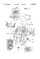
- FIG. 1 is a part of an explode perspective view showing a clamp-operated retractor, which constitutes a first embodiment of this invention.
- FIG. 2 is the remaining of the exploded perspective view showing the clamp-operated retractor.
- FIGS. 3 through 5 are side views, with parts cut away, for a description of the operation of a clamping mechanism in the clamp-operated retractor shown in FIG. 1.
- FIG. 6 is an enlarged diagram showing essential components of an emergency locking mechanism in the clamp-operated retractor shown in FIG. 1.
- FIG. 7 is an enlarge perspective view of an upper stay shown in FIG. 1.
- FIG. 8(a) is a fragmentary sectional view of the upper stay shown in FIG. 7 which is to be mounted on the base of the clamp-operated retractor, and the FIG. 8(b) is also a fragmentary sectional view of the upper stay which is mounted on the base.
- FIG. 9 is an enlarged side view showing the upper stay shown in FIG. 1 which is mounted on the base.
- FIG. 10 is a fragmentary sectional view showing an upper stay mounted on the base in another embodiment of the invention.
- FIG. 11 is a fragmentary sectional view showing an upper stay to be mounted on the base in another embodiment of the invention.
- FIG. 12 is a fragmentary sectional view showing an upper stay to be mounted on the base in another embodiment of the invention.
- FIGS. 1 and 2 are exploded perspective views showing a clamp-operated retractor, which constitutes a first embodiment of the invention.
- a base 1 is substantially U-shaped in section, and has two side boards 1a confronted with each other.
- the side boards la have through-holes 1c, respectively.
- a winding shaft 4, on which a bobbin 2 is fixedly mounted, is swingably inserted through right and left plastic bushings 3b and 3a into the through-holes 1c of the side boards 1a.
- a webbing is wound on the bobbin 2.
- a conventional tension reducer 5 is mounted on one end portion of the winding shaft 4, so that the latter 4 is urged to take up the webbing at all times.
- an emergency locking mechanism is provided at the other end of the winding shaft 4.
- the emergency locking mechanism is to prevent the webbing from being pulled out.
- the emergency locking mechanism includes a latch plate 4a which is a ratchet wheel fixedly mounted on the other end portion of the winding shaft 4 in such a manner that the latter 4 is protruded from the outer surface of the ratchet wheel.
- a tension plate 9 having a through-hole 9c, and a latch cup 13 which is a latch member having internal teeth 13a are loosely mounted on the end portion of the winding shaft 4 thus protruded.
- a return spring 12 is connected between the spring hanger 13b of the latch cup 13 and the spring hanger 9a of the tension plate 9, so that the latch cup 13 is urged to turn in the direction of the arrow X 2 .
- Locking means, and a conventional inertial member are provided on the end portion of the winding shaft 4 which is exposed outside the latch cup 13, so that, when tension is applied to the webbing in an emergency thereby to abruptly apply an excessively great torque to the winding shaft 4 in a webbing pull-out direction (or in the direction of the arrow X 1 ), the latch cup 13 is turned in the direction of the arrow X 1 against the elastic force of the return spring 12.
- reference numeral 11 designates a pawl which engages with the latch plate 4a to stop the rotation of the latter 4a in the webbing pull-out direction (in the direction of the arrow X 1 ).
- the pawl 11 is detachably supported on a pawl pin 10 outside the side board 1a.
- the pawl pin 10 is inserted into a through-hole 27 formed in one side board la and an elongated hole 21 formed in the other side board 1a, and therefore the pawl pin 10 is swingable along the elongated hole 21 with its portion as a fulcrum which is engaged with the through-hole 27.
- the outer end portion 10b of the pawl pin 10 is inserted into a through-hole 9b formed in a first swinging portion of the tension plate 9. Therefore, the swinging rotation center of the pawl 11 can be shifted along the elongated hole 21.
- a pawl guide protrusion 11b is extended from the pawl 11, and it is inserted into a pawl guide hole 13c formed in the outer periphery of the latch cup 13.
- a sensor casing 31 forming vehicle body acceleration sensing means 30 is fixedly provided below the side boards 1a. Inside the sensor case 31, a ball weight 33 serving as a sensor is provided, and a sensor arm 32 with a locking protrusion 32a is swingably mounted. A sensor cover 14 is provided outside the side board 1a which covers the emergency locking mechanism constructed as described above.
- a clamping mechanism is provided inside the base 1, which holds the webbing directly, thereby to prevent the webbing from being pulled out.
- FIG. 3 is a fragmentary side view, with parts cut away, showing the clamping mechanism.
- the clamping mechanism comprises: a clamp 6 which is a wedge-shaped clamp member having clamp teeth 6c which are to tighten the webbing 26; and an upper stay 19 holding an upper plate 20.
- the upper plate 20 is a guide member adapted to slidably contact a planar portion 6d opposite to a planar portion where the clamp teeth 6c are formed.
- the upper stay 19 has mounting holes 19b which are engaged with protrusions 1d of the side boards 1a, and a mounting plate 19a to which the upper plate 20 is secured with screws. That is, the upper stay 19 is a mounting member for regulating the longitudinal movement of the upper plate 20.
- the upper stay 19 is made up of a plate member such as a thin metal plate having a predetermined configuration which is formed by blanking. Both end portions of the mounting plate 19a are bent into hooking portions 19c which are engaged with the edges of the side boards 1a.
- the hooking portions 19c have mounting holes 19b, respectively, and the hooking portions 19c include: pushing pieces 19e which, when the upper stay 19 is secured to the base 1, push the upper edges of the side boards la; and pushing portions 19d which, in the same case, push the side boards la inwardly of the base.
- the upper stay 19 is shaped as shown in the parts (a) and (b) of FIG. 8. That is, it is so shaped that the bend angle ⁇ 1 which each of the hooking portions 19c forms with the mounting plate 19a before the upper stay 19 is coupled to the base is larger than that ⁇ 2 after coupled to the base.
- the upper plate 20 is urged with respect to the base 1 both in the direction of the arrow A and in the direction of the arrow B.
- the upper plate 20 is accurately positioned with its both end portions pushed against the upper corners of the through-holes 24 formed in the side boards 1a.
- the pushing portions 19d of the upper stay 19 push the side boards la inwardly of the base 1, as a result of which the upper plate 20 is secured to the base without play in the longitudinal direction.
- the upper stay 19 has the elastically deformable portions adapted to urge the upper plate 20 in the above-described directions.
- the fixed position, and the angle of inclination of the upper plate 20 are positively determined with the aid of the through-holes 24; that is, the upper plate 20 thus mounted has no play.
- the embodiment is free from the problems that would result if the upper plate 20 is not settled because of dimensional errors between the upper stay 19 and the base 1, or it is impossible to completely secure the upper stay 19 to the upper plate 20 with the screws because the former 19 is not in close contact with the latter 20.
- the upper plate 20 is fixedly secured to the mounting plate 19a of the upper stay 19 after both end portions thereof are engaged with the through-holes 24 formed in the side boards 1a. Therefore, the upper plate 20 is so positioned that its slide contact surface 21 for guiding the clamp 6 to the webbing tightening position forms a predetermined angle with a lower plate 16 which is fixedly secured to the back board 1b of the base in such a manner that the distance between the slide contact surface 21 and the lower plate 16 is shorter as one moves upwardly.
- the clamp 6 is so positioned that, with its acute end portion at the top, the planar portion 6d is in surface contact with the slide contact surface 20a of the upper plate 20.
- the clamping teeth 6c of the clamp 6 thus positioned are set in parallel with the surface of the webbing 26 at all times, and therefore the clamp 6 sliding on the slide contact surface 20a of the upper plate 20 is able to uniformly fasten the webbing 26.
- a return spring 15 is connected between an engaging portion 6b protruded from the rear end of the clamp 6 and the rear end face 20b of the upper plate 20, to urge the clamp 6 so that the latter 6 may not engage with the webbing 26.
- a clamp lever 7 is provided below the clamp 6 to regulate the movement of the clamp 6 which is urged by the return spring 15.
- the clamp lever 7 together with an outer plate 8 form a lever member which is interlocking means for moving the clamp 6 in the webbing tightening direction in association with the emergency locking mechanism.
- the outer plate 8 is provided outside the side board la and engaged with the above-described tension plate 9.
- the clamp lever 7 comprises: a pair of plate-shaped members 7a and 7b which have slots 7f and 7f, respectively, which are engaged with shafts 6a and 6a protruded from the side walls of the clamp 6; and a coupling part 7c which is connected between those plate-shaped members 7a and 7b and abutted against the rear end wall of the clamp 6.
- the plate-shaped members 7a and 7b are swingably supported on a lever pin 17, which is inserted into holes 7d formed in the plate-shaped members 7a and 7b, and through-holes 23 which are formed in the side boards 1a in such a manner that they are in alignment with the holes 7d, respectively.
- the outer plate 8 comprises: an inside shaft 8a which is extended inwardly through the elongated hole 22 of the side board la to engage with an engaging hole 7e formed in the plate-shaped member 7a; and an abutting part 8c which is engaged with an engaging part 9d of a second swinging end portion of the above-described tension plate 9.
- the clamp lever 7, being prevented from turning downwardly with the inside shaft 8a locked to the elongated hole 22, regulates the movement of the clamp 6 against the elastic force of the return spring 15. That is, in the clamp 6, its shafts 6a are engaged with the slots 7f formed in the swinging end portions of the plate-shaped members 7a and 7b, and its rear end wall is supported by the coupling part 7c, and therefore its clamping teeth 6c are held in such a manner that they are not in engagement with the webbing 26. Hence, when the outer plate 8 is turned upwardly, the clamp lever 7 is turned upwardly through the inside shaft 8a of the outer plate 8.
- the clamp lever 7 thus turned pushes the shafts 6a of the clamp 6 against the elastic force of the return spring 15, as a result of which the clamp 6 is moved to engage with the webbing 26 while the planar portion 6d is being slidably moved on the slide contact surface 20 of the upper plate 20.
- the aforementioned elongated hole 22 will not interfere with the inside shaft 8a of the outer plate 8.
- the engaging part 9d of the second swinging portion of the tension plate 9 is pushed downwardly (in FIG. 2) by the outer plate 8 to which the elastic force of the return spring 15 is applied which is greater than that of the return spring 12; that is, the tension plate 9 is urged to turn in the direction of the arrow X 2 in FIG. 2.
- the pawl pin 10 is urged in the webbing winding direction on the side of one end 21a of the elongated hole 21 which is on the back board side.
- the lever member comprising the clamp lever 7 and the outer plate 8, and the tension plate 9 form control means for moving the clamp 6 in the webbing holding direction to position the latter 6 at a first position where pulling the webbing is prevented, and a second position where pulling the webbing is permitted.
- the clamp-operated retractor thus constructed operates as follows:
- the inside shaft 8a of the outer plate 8, which is engaged with the engaging hole 7e of the clamp lever 7, is positioned on the bottom of the elongated hole 22 by the elastic force of the return spring 15, and the clamp 6 is urged by the elastic force of the return spring 15 so as not to engage with the webbing 26.
- the latch cup 13 is urged in the direction of the arrow X 2 by the return spring 12 connected between the spring hanger 13b of the latch cup 13 and the spring hanger 9a of the tension plate 9, while the pawl 11 whose pawl guide protrusion 11b is engaged with the pawl guide hole 13c is urged so as not to engage with the latch plate 4a.
- webbing 26 can be freely pulled out.
- the webbing is kept not in contact with the clamp teeth 6c with the aid of the aforementioned coupling part 7c and a webbing guide pin 18 which are inserted into through-holes 25 formed in the upper portion of the side boards 1a.
- tension is applied to the webbing 26. That is, when a torque greater than the predetermined value is applied to the winding shaft 4 in the webbing pull-out direction (i.e., in the direction of the arrow X 1 ), an inertial force is applied to the inertial member (not shown), so that the rotation of the winding shaft 4 in the webbing pull-out direction is delayed.
- the locking means operates; that is, the engaging portion 28a of a locking member 28 is engaged with the internal teeth 13a of the latch cup 13, and therefore the torque of a flange 27 is transmitted to the latch cup 13.
- the latch cup 13 is turned in the direction of the arrow X 1 against the elastic force of the return spring 12.
- the engaging part 9d of the tension plate 9 turns the outer plate 8 in the direction of the arrow Y through the abutting part 8c of the outer plate, and therefore the clamp lever 7 is turned in the direction of the arrow Y with the aid of the inside shaft 8a engaged with the elongated hole 22.
- the clamp 6, being engaged with the slots 7f formed in the swinging end portions of the clamp lever 7, is immediately moved upwardly along the slide contact surface 20a of the upper plate 20.
- the slide contact surface 20a is so inclined with respect to the lower plate 16 that the distance between the slide contact surface 20 and the lower plate 16 is shorter upwardly, as was described before.
- the wedge-shaped clamp 6 moved upwardly against the elastic force of the return spring 15 moves in the webbing holding direction (i.e., in the direction of the arrow W), so that the webbing 26 is positively held between the slide contact surface 20a and the lower plate 16 in such a manner that it is nipped between them. That is, the webbing 26, being positively held between the clamp 6 and the lower plate 16, is prevented from being pulled out.
- the movement of the pawl pin 10 supporting the pawl 11 is stopped when the pawl pin 10 abuts against the end 21b, on the front side, of the elongated hole 21, so that the winding shaft 4 is prevented from being turned in the direction of the arrow X 1 .
- the timing that the pawl pin 10 abuts against the end 21b of the elongated hole 21 is so determined that it occurs immediately after the clamping teeth 6c have completely bit into the webbing 26.
- the operating timing of the clamp 6 and the pawl 11 can be freely changed by changing the configuration of the abutting part 8c of the outer plate 8 and that of the elongated hole 21 of the side board 1a.
- the above-described vehicle body acceleration sensing means 30 activates the locking means, and the clamping mechanism and the emergency locking means operate in the above-described manner.
- the engaging portion 28a of the locking member 28 is disengaged from the internal teeth 12a of the latch cup 13, so that the latter 13 is turned in the direction of the arrow X 2 by the elastic force of the return spring 12 to the original position, whereby the webbing can be freely pulled out.
- the locking means of the emergency locking mechanism is activated to turn the latch cup 13 in the webbing pull-out direction
- the pawl 11 is engaged with the latch plate 4a, so that the tension plate 9 is turned in the webbing pull-out direction by the torque of the winding shaft 4, and the lever member made up of the clamp lever 7 and the outer plate 8 is turned by the tension plate 9 to move the clamp 6 in the webbing holding direction.
- the webbing 26 can be positively prevented from being pulled out.
- the clamp-operated retractor unlike the transfer member in the conventional clamping mechanism, it is unnecessary to provide, in addition to the pawl 11, a locking member engaging with the latch plate 4a mounted on the winding shaft 4, which reduces the number of components of the clamp-operated retractor as much, and contributes to simplification of the construction and to reduction of the manufacturing cost.
- an engaging protrusion is formed on the clamp 6 in such a manner that it is inserted into the elongated hole formed in the side board 1a, and a cam surface which is engaged with the engaging protrusion is formed on the tension plate 9 so that, in association with the swing of the tension plate 9, the clamp 6 is moved to the first position where pulling the webbing 26 is prevented and to the second position where pulling the webbing is permitted; that is, a cam mechanism is formed as interlocking means between the tension plate 9 and the clamp 6.
- the number of components of the transfer means can be further reduced which is required to transfer the rotation of the latch cup 13 to the clamp 6 to cause the latter 6 to clamp the webbing, and accordingly the energy loss due to the play thereof can be decreased. Therefore, the webbing 26 can be quickly prevented from being pulled out; that is, the clamp 6 is able to clamp the webbing immediately when the inertia sensing means detects the collision.
- the clamp lever, the outer plate, and the tension plate, which provide the interlocking means which forms the control means in the clamp-operated retractor of the invention are not limited those which have been described above. That is, it goes without saying that they may be changed and modified in various manners without departing from the invention.
- FIG. 10 is a fragmentary sectional view of an upper stay 40 mounted in a third embodiment of the invention.
- the upper stay 40 includes a mounting plate 40a, both end portions of which are bent into hooking portions 40c which are engaged with the edges of the side boards 1a.
- the hooking portions 40c have mounting holes 40b, respectively, and the hooking portions 40c include: pushing pieces 40e which, when the upper stay 40 is secured to the base 1, push the upper edges of the side boards 1a; and pushing portions 40d which, in the same case, push the side boards 1a inwardly of the base.
- the coupling portions between the mounting plate 40a and the hooking portions 40c are formed into elastically bendable portions 41.
- the mounting plate 40a is parallelly movable towards the back board 1b so that the upper plate 20 secured to the base with both ends engaged with the through-holes 24 is urged in the direction of the arrow A.
- the upper stay 40 urges the upper plate 20 in the direction of the arrow A in FIG. 10 with the aid of the elastic restoring force of the elastic bent portions 41, and the pushing pieces 40e push the upper edges of the side boards 1b.
- the upper plate 20 is positioned accurately with its both end portions pushed against the upper corners of the through-holes 24.
- FIG. 11 shows an upper stay 42 in a fourth embodiment.
- the upper stay 42 includes a mounting plate 42a, both end portions of which are bent into hooking portions 42c which are engaged with the edges of the side boards 1a.
- the hooking portions 42c have mounting holes 42b, respectively, and include: pushing pieces 42e at the ends which, when the upper stay 42 is secured to the base 1, push the upper edges of the side boards 1a; and pushing portions 42d which, in the same case, push the side boards 1a inwardly of the base.
- a bead 43 is formed on the inner surface of each of the hooking portions 42c to allow the inner surface wall of the latter which confronts with the inner surface of the respective side board 1a and the inner surface around the through-hole 42b to smoothly merge with each other.
- the protrusions 1d of the side boards 1b slidably contact the inner surfaces of the hooking portions 42c, so that the latter 42c are elastically deformed inwardly.
- the protrusions 1d are smoothly engaged with the mounting holes 42b being guided by the beads 43, which improves the assembling efficiency of the clamp-operated retractor.
- FIG. 12 shows an upper stay 44 in a fifth embodiment.
- the upper stay 44 includes a mounting plate 44a, both end portions of which are bent into hooking portions 44c which are engaged with the edges of the side boards 1a.
- the hooking portions 44c have mounting holes 44b, respectively, and include: pushing pieces 44e at the ends which, when the upper stay 44 is secured to the base 1, push the upper edges of the side boards 1a; and pushing portions 44d which, in the same case, push the side boards 1a inwardly of the base. More specifically, each of the hooking portions 44c is bent at a position where its the inner surface which confronts with the inner surface of the respective side board 1a is substantially flush with the inner surface around the mounting hole 44b.
- the protrusions 1d of the side boards 1b slidably contact the inner surfaces of the hooking portions 44c, so that the latter 44c are elastically deformed inwardly. In this operation, the protrusions 1d are smoothly engaged with the mounting holes 44b. This means that the retractor of the invention can be assembled with high efficiency.
- the wedge-shaped clamping member namely, the clamp 6 is moved along the upper plate 20, to clamp the webbing 26 on the upper plate 16.
- a clamping member is employed which comprises a clamp holder which is swingably supported, and a clamp is held on the clamp holder at the swinging end.
- the swinging end portion of a lever member having an abutting part which is abutted against the engaging part formed in the second swinging end portion of the tension plate is engaged with the clamp holder, so that the clamp holder is swung in the webbing holding direction by the rotation of the tension plate.
- an engaging protrusion adapted to engage with a cam surface formed in the second swinging end portion of the tension plate is extended from the clamp holder, so that the clamp holder is directly swung in the webbing holding direction by the rotation of the tension plate.
- the emergency locking mechanism is designed as described above; however, the invention is not limited thereto or thereby. That is, the technical concept of the invention is applicable to a clamp-operated retractor having an emergency locking mechanism comprising inertia sensing means and locking means which are different from those which have been described.
- the control means for moving the clamp member in the webbing holding direction to position the clamp member at the first position where pulling the webbing is prevented and at the second position where pulling the webbing is permitted comprises: the tension plate which is so arranged to be rotatable around the same axis as that of the ratchet wheel, and urges the latch member in the webbing winding direction and rotatably supports the pawl member; and the interlocking means which is driven in association with the rotation of the tension plate, to move the clamp member to the first or second position.
- the clamp-operated retractor unlike the transfer member in the conventional clamping mechanism, it is unnecessary to have, in addition to the pawl member, a locking member engaging with the ratchet wheel mounted on the winding shaft. This means that the number of components can be reduced as much, and the resultant clamp-operated retractor is accordingly simplified in construction and reduced in manufacturing cost.
- the number of components of the transfer means can be further reduced which is required to transfer the rotation of the latch member to the clamp member to cause the latter to clamp the webbing, and accordingly the energy loss due to the play of the transfer means can be decreased.
- the webbing is quickly stopped from being pulled out; that is, the clamp member is able to clamp the webbing immediately when the inertia sensing means detects the collision.
- the retractor including the emergency locking mechanism adapted to lock the rotation of the winding shaft in the webbing pull-out direction in an emergency such as collision, in which the webbing clamping mechanism able to quickly stop the webbing from being pulled out is simple in structure, can be provided at low manufacturing cost according to the invention.
Landscapes
- Engineering & Computer Science (AREA)
- Mechanical Engineering (AREA)
- Automotive Seat Belt Assembly (AREA)
Abstract
Description
Claims (13)
Applications Claiming Priority (4)
| Application Number | Priority Date | Filing Date | Title |
|---|---|---|---|
| JP4-093220U | 1992-12-25 | ||
| JP9322092 | 1992-12-25 | ||
| JP1993058830U JP2599175Y2 (en) | 1992-12-25 | 1993-10-05 | Retractor with clamp |
| JP5-058830U | 1993-10-05 |
Publications (1)
| Publication Number | Publication Date |
|---|---|
| US5460338A true US5460338A (en) | 1995-10-24 |
Family
ID=26399842
Family Applications (1)
| Application Number | Title | Priority Date | Filing Date |
|---|---|---|---|
| US08/172,249 Expired - Fee Related US5460338A (en) | 1992-12-25 | 1993-12-23 | Retractor having a clamping mechanism |
Country Status (2)
| Country | Link |
|---|---|
| US (1) | US5460338A (en) |
| JP (1) | JP2599175Y2 (en) |
Cited By (4)
| Publication number | Priority date | Publication date | Assignee | Title |
|---|---|---|---|---|
| US5588609A (en) * | 1994-04-13 | 1996-12-31 | Nsk Ltd. | Seat belt winding device |
| US5624086A (en) * | 1995-09-01 | 1997-04-29 | Trw Vehicle Safety Systems, Inc. | Seat belt retractor |
| US5678782A (en) * | 1994-12-27 | 1997-10-21 | Nsk Ltd. | Retractor having a clamp |
| US5735479A (en) * | 1993-10-26 | 1998-04-07 | Nsk Ltd. | Retractor for seat belt |
Citations (12)
| Publication number | Priority date | Publication date | Assignee | Title |
|---|---|---|---|---|
| US4241886A (en) * | 1978-09-08 | 1980-12-30 | Mitsubishi Jidosha Kogyo Kabushiki Kaisha | Retractor device for seat belt mechanism |
| US4437623A (en) * | 1982-09-21 | 1984-03-20 | American Safety Equipment Corporation | Integrated weblocker with program pawl retractor |
| US4786079A (en) * | 1986-11-26 | 1988-11-22 | American Safety Corporation | Web guide and emergency locking assembly |
| US4854644A (en) * | 1986-08-27 | 1989-08-08 | Britax-Kolb Gmbh & Co. | Deflection clamping device |
| US4928902A (en) * | 1988-07-27 | 1990-05-29 | Takata Corporation | Vehicle seat belt retractor |
| JPH03112750A (en) * | 1989-09-27 | 1991-05-14 | Takata Kk | Seat belt retractor |
| US5029769A (en) * | 1989-01-26 | 1991-07-09 | Trw Repa Gmbh | Safety belt retractor having webbing clamping means |
| US5044575A (en) * | 1987-09-16 | 1991-09-03 | Autoliv-Kolb Gmbh & Co. | Belt retractor apparatus for a seat belt system comprising a belt retractor |
| US5127598A (en) * | 1989-09-11 | 1992-07-07 | Takata Corporation | Seat belt retractor |
| US5232178A (en) * | 1991-04-25 | 1993-08-03 | Nsk Ltd. | Retractor with clamping mechanism |
| US5299854A (en) * | 1991-01-28 | 1994-04-05 | Takata Corporation | Seat belt retractor locking mechanism using deformable force reducing portion |
| US5364048A (en) * | 1992-04-06 | 1994-11-15 | Takata Corporation | Seat belt retractor |
-
1993
- 1993-10-05 JP JP1993058830U patent/JP2599175Y2/en not_active Expired - Fee Related
- 1993-12-23 US US08/172,249 patent/US5460338A/en not_active Expired - Fee Related
Patent Citations (12)
| Publication number | Priority date | Publication date | Assignee | Title |
|---|---|---|---|---|
| US4241886A (en) * | 1978-09-08 | 1980-12-30 | Mitsubishi Jidosha Kogyo Kabushiki Kaisha | Retractor device for seat belt mechanism |
| US4437623A (en) * | 1982-09-21 | 1984-03-20 | American Safety Equipment Corporation | Integrated weblocker with program pawl retractor |
| US4854644A (en) * | 1986-08-27 | 1989-08-08 | Britax-Kolb Gmbh & Co. | Deflection clamping device |
| US4786079A (en) * | 1986-11-26 | 1988-11-22 | American Safety Corporation | Web guide and emergency locking assembly |
| US5044575A (en) * | 1987-09-16 | 1991-09-03 | Autoliv-Kolb Gmbh & Co. | Belt retractor apparatus for a seat belt system comprising a belt retractor |
| US4928902A (en) * | 1988-07-27 | 1990-05-29 | Takata Corporation | Vehicle seat belt retractor |
| US5029769A (en) * | 1989-01-26 | 1991-07-09 | Trw Repa Gmbh | Safety belt retractor having webbing clamping means |
| US5127598A (en) * | 1989-09-11 | 1992-07-07 | Takata Corporation | Seat belt retractor |
| JPH03112750A (en) * | 1989-09-27 | 1991-05-14 | Takata Kk | Seat belt retractor |
| US5299854A (en) * | 1991-01-28 | 1994-04-05 | Takata Corporation | Seat belt retractor locking mechanism using deformable force reducing portion |
| US5232178A (en) * | 1991-04-25 | 1993-08-03 | Nsk Ltd. | Retractor with clamping mechanism |
| US5364048A (en) * | 1992-04-06 | 1994-11-15 | Takata Corporation | Seat belt retractor |
Cited By (4)
| Publication number | Priority date | Publication date | Assignee | Title |
|---|---|---|---|---|
| US5735479A (en) * | 1993-10-26 | 1998-04-07 | Nsk Ltd. | Retractor for seat belt |
| US5588609A (en) * | 1994-04-13 | 1996-12-31 | Nsk Ltd. | Seat belt winding device |
| US5678782A (en) * | 1994-12-27 | 1997-10-21 | Nsk Ltd. | Retractor having a clamp |
| US5624086A (en) * | 1995-09-01 | 1997-04-29 | Trw Vehicle Safety Systems, Inc. | Seat belt retractor |
Also Published As
| Publication number | Publication date |
|---|---|
| JPH0661610U (en) | 1994-08-30 |
| JP2599175Y2 (en) | 1999-08-30 |
Similar Documents
| Publication | Publication Date | Title |
|---|---|---|
| JP3674800B2 (en) | Seat belt retractor | |
| JP3787001B2 (en) | Seat belt retractor | |
| EP0768219B1 (en) | Webbing take-up device | |
| JP2004090672A (en) | Webbing winder | |
| US5460338A (en) | Retractor having a clamping mechanism | |
| JPH0627384U (en) | Seat belt retractor | |
| JPH1059128A (en) | Seat belt retractor | |
| US5820059A (en) | Retractor for seat belt | |
| JPH08133011A (en) | Webbing winding device | |
| JPH10230817A (en) | Retractor for seat belt | |
| US4809926A (en) | Webbing retractor | |
| JP2653764B2 (en) | Vehicle seat belt retractor | |
| JPH09226518A (en) | Retractor meshing mechanism | |
| US5495993A (en) | Retractor for seat belt | |
| JP3335004B2 (en) | Lock structure of retractor | |
| JP3683648B2 (en) | Seat belt retractor | |
| JP3547546B2 (en) | Seat belt retractor | |
| JPH07232617A (en) | Retractor for seat belt | |
| JPH08175324A (en) | Retractor fitted with clamp | |
| JPH0711460U (en) | Retractor with clamp | |
| JP3609218B2 (en) | Seat belt retractor | |
| JP3032687B2 (en) | Webbing take-up device | |
| JP2586841Y2 (en) | Seat belt retractor | |
| JPH03231055A (en) | Clamping device for seat belt | |
| JPH0727967U (en) | Retractor with clamp |
Legal Events
| Date | Code | Title | Description |
|---|---|---|---|
| AS | Assignment |
Owner name: NSK LTD., JAPAN Free format text: ASSIGNMENT OF ASSIGNORS INTEREST;ASSIGNORS:HIRATA, KAZUMI;SASAKI, TAKANOBU;MATSUKI, MASUO;AND OTHERS;REEL/FRAME:006819/0394 Effective date: 19931214 |
|
| FEPP | Fee payment procedure |
Free format text: PAYOR NUMBER ASSIGNED (ORIGINAL EVENT CODE: ASPN); ENTITY STATUS OF PATENT OWNER: LARGE ENTITY |
|
| FPAY | Fee payment |
Year of fee payment: 4 |
|
| FPAY | Fee payment |
Year of fee payment: 8 |
|
| AS | Assignment |
Owner name: NSK AUTOLIV CO., LTD., JAPAN Free format text: ASSIGNMENT OF ASSIGNORS INTEREST;ASSIGNOR:NSK, LTD.;REEL/FRAME:014261/0353 Effective date: 20030106 |
|
| REMI | Maintenance fee reminder mailed | ||
| LAPS | Lapse for failure to pay maintenance fees | ||
| STCH | Information on status: patent discontinuation |
Free format text: PATENT EXPIRED DUE TO NONPAYMENT OF MAINTENANCE FEES UNDER 37 CFR 1.362 |
|
| FP | Lapsed due to failure to pay maintenance fee |
Effective date: 20071024 |