US5437357A - Bill identification apparatus - Google Patents
Bill identification apparatus Download PDFInfo
- Publication number
- US5437357A US5437357A US08/170,402 US17040293A US5437357A US 5437357 A US5437357 A US 5437357A US 17040293 A US17040293 A US 17040293A US 5437357 A US5437357 A US 5437357A
- Authority
- US
- United States
- Prior art keywords
- value
- bill
- heterogeneity
- bills
- data
- Prior art date
- Legal status (The legal status is an assumption and is not a legal conclusion. Google has not performed a legal analysis and makes no representation as to the accuracy of the status listed.)
- Expired - Fee Related
Links
Images


Classifications
-
- G—PHYSICS
- G07—CHECKING-DEVICES
- G07F—COIN-FREED OR LIKE APPARATUS
- G07F7/00—Mechanisms actuated by objects other than coins to free or to actuate vending, hiring, coin or paper currency dispensing or refunding apparatus
- G07F7/04—Mechanisms actuated by objects other than coins to free or to actuate vending, hiring, coin or paper currency dispensing or refunding apparatus by paper currency
-
- G—PHYSICS
- G07—CHECKING-DEVICES
- G07D—HANDLING OF COINS OR VALUABLE PAPERS, e.g. TESTING, SORTING BY DENOMINATIONS, COUNTING, DISPENSING, CHANGING OR DEPOSITING
- G07D7/00—Testing specially adapted to determine the identity or genuineness of valuable papers or for segregating those which are unacceptable, e.g. banknotes that are alien to a currency
- G07D7/06—Testing specially adapted to determine the identity or genuineness of valuable papers or for segregating those which are unacceptable, e.g. banknotes that are alien to a currency using wave or particle radiation
- G07D7/12—Visible light, infrared or ultraviolet radiation
-
- G—PHYSICS
- G07—CHECKING-DEVICES
- G07D—HANDLING OF COINS OR VALUABLE PAPERS, e.g. TESTING, SORTING BY DENOMINATIONS, COUNTING, DISPENSING, CHANGING OR DEPOSITING
- G07D7/00—Testing specially adapted to determine the identity or genuineness of valuable papers or for segregating those which are unacceptable, e.g. banknotes that are alien to a currency
- G07D7/181—Testing mechanical properties or condition, e.g. wear or tear
- G07D7/187—Detecting defacement or contamination, e.g. dirt
Definitions
- the present invention relates to a bill identification apparatus fop use in an automatic vending machine, exchange machine, game machine, etc.
- Bill identification apparatuses fop determining the type and authenticity of bills ape conventionally proposed and described in Japanese Patent KOKOKU Publication Nos. 63-26918, 64-5854, fop example. These apparatuses ape designed so that sampling data are obtained by detecting colors and shades on various parts of the bills of magnetic particulates contained in ink on the bills by means of sensors as the bills are transported, and the obtained data ape compared with reference patterns.
- authentic bill signals for types of bills corresponding to the reference patterns ape outputted only when all the data sampled in individual positions are within their respective tolerances with respect to data fop the reference patterns.
- the reliability of the classification and authentication depends solely on deviations between the values of the sampling data and the reference pattern data fop the individual positions.
- the tolerances as criteria must be made considerably small. If the tolerances ape too small, however, authentic bills may possibly be concluded to be false when the values of the detected data are uniformly shifted due to stains all over the circulating bills.
- Japanese Patent KOKOKU Publication No. 58-9990 To cope with fluctuations of the detected data attributable to soiling or aging of the bills, shifts of the detected data values due to changes of the ambient temperature, etc., an improved bill identification apparatus is proposed and described in Japanese Patent KOKOKU Publication No. 58-9990. According to this apparatus, detected data are corrected by means of the average of the data sampled in individual positions, and the corrected data are compared with reference patterns. If an authentic bill is partially changed in properties by soiling, in this case, however, it will inevitably be rejected as a false bill.
- Japanese Patent KOKAI Publication No. 2-148383 Proposed in Japanese Patent KOKAI Publication No. 2-148383, moreover, is a bill identification apparatus which is arranged so that the relationships between reference data for individual bill types and frequency distributions are previously stored, and operations for decision are performed on the basis of the fuzzy theory. Even though the detected data themselves are subject to fluctuations, this apparatus carries out no corrective operation to maintain conformity between the detected data and frequency distribution data as
- the present invention provides a bill identification apparatus which is hardly subject to decision errors attributable to fluctuations of detected data caused by aging or partial soiling of bills, and can smoothly perform decision operation without increasing the memory capacity of memory means or excessively loading an arithmetic unit.
- Fluctuations of detected data pi attributable to deterioration of bills and aging of detecting means equally affect the data pi detected in various detection positions i. Accordingly, scattering of the data caused by the deterioration or aging of the bills and the detecting means can be corrected by preparing modified detected data pm.pi, which is a product of the detected data pi for the detection positions i and a correction value pm.
- the correction value pm is obtained by dividing the sum total ⁇ pci of standard pattern values pci by an integrated value ⁇ pi of the detected data pi for an entire detection section.
- the deviation phi thus obtained is equivalent to a sample from a population which has a 0-average 1-variance standard normal distribution, and that the sum of the squares of the deviation complies with the ⁇ 2 distribution.
- a heterogeneity pr indicative of the correlation between the respective diagram forms of the modified detected data pm.pi and the authentic standard data pci is defined as the following equation (4), the heterogeneity pr complies with the ⁇ 2 distribution, and the modified detected data pm.pi for each position i is associated with the probability which pertains to the diagram form of the authentic standard data pci. ##EQU1##
- the general soiling and deterioration of the detecting means and the bill are substantially homogeneous.
- the respective values of correction factors pmj of the individual detecting means should be substantially equal to one another.
- discriminating means outputs no authentic bill signal.
- a bill identification apparatus which comprises: transportation means for transporting bills along a transportation path; detecting means in the transportation path for sampling the bills in synchronism with the bill transportation speed, detecting the physical properties of the bills in each of detection positions i, and outputting detected data pi for the detected properties; memory means for storing standard pattern values pci, indicative of average values for the individual detection positions i computed in accordance with the detected data pi obtained by sampling a number of authentic bills by the detecting means, and standard deviation values psi indicative of the degrees of scattering of data in the detection positions i; correction value computing means for obtaining a correction value pm for making an average value for a detection section for the detected data pi, detected by sampling the bills to be identified by the detecting means, equal to an average value fop a detection section for the standard pattern value pci; heterogeneity computing means for obtaining a heterogeneity pr by correcting the detected data pi, detected by sampling the bills to be identified by the detecting
- the memory means further stores the sum total ⁇ pci of the standard pattern values pci for the detection section and the sum total ⁇ (pci/psi) 2 of the square of each standard pattern value pci divided by each corresponding standard deviation value psi for the detection section;
- the correction value computing means successively integrates the detected data pi delivered from the detecting means in the detection section, and obtains the correction value pm by dividing the sum total ⁇ pci of the standard pattern values pci by the resulting integrated value ⁇ pi when the detection section terminates;
- the heterogeneity computing means successively obtains an integral ⁇ (pi/psi) 2 of the square of the detected data pi divided by the deviation value psi in the corresponding position and an integral ⁇ (pi.pci/psi 2 ) of a value obtained by dividing the product of the detected data pi and the corresponding standard pattern value pci by the square of the deviation value psi, and
- the data required for the computation of the heterogeneity pr are obtained by integrative processing and stored in succession, so that the necessary memory capacity for the retention of the detected data can be saved, the load required for the arithmetic processing of the heterogeneity computing means can be reduced, and the time for the computation of the heterogeneity can be shortened.
- the detecting means comprises a plurality of detecting means Pj arranged in an offset manner in a direction perpendicular to the direction of transportation of the bills; the memory means stores average values, standard pattern values pcij, and deviation values psij for the individual detecting means Pj; the correction value computing means and the heterogeneity computing means obtain correction values pmj and heterogeneities prj, respectively, for the individual detecting means Pj; and the discriminating means concludes that the bills transported thereto are authentic only when all the correction values and the heterogeneities are within the respective tolerances thereof.
- the memory means stores sum total ⁇ (pcij/psij) 2 of the square of each standard pattern value pcij divided by each corresponding standard deviation value psij for the detection section; the correction value computing means and the heterogeneity computing means obtain correction values pmj and heterogeneities prj, respectively, for the individual detecting means Pj; and the discriminating means concludes that the bills transported thereto are authentic only when all the correction values and the heterogeneities are within the respective tolerances thereof.
- the bill identification apparatus further comprises correction value scattering detecting means for detecting the degrees of scattering of the correction values pmj of the individual detecting means Pj, and the discriminating means concludes that the bills are authentic only when all the correction values, heterogeneities, and scattering degrees are within the respective tolerances thereof.
- the authenticity of the bills can be judged by determining whether or not the computed correction values serve to correct the scattering of the data attributable to general soiling or deterioration of the bills.
- the bill identification apparatus further comprises overall heterogeneity computing means for obtaining an overall heterogeneity ⁇ prj by summing up the heterogeneities prj for the individual detecting means Pj, and the discriminating means does not conclude that the bills are authentic when the overall heterogeneity ⁇ prj is not within the tolerance thereof.
- the authenticity of the bills can be determined exactly on the basis of synthetic evaluation by means of the individual detecting means.
- the memory means stores each data corresponding to the type of the bills, the correction value computing means, the heterogeneity computing means, and the overall heterogeneity computing means obtain the correction value, heterogeneity, and overall heterogeneity, respectively, for each bill type, and the discriminating means outputs authentic bill signals corresponding to the bills of types such that the correction value, heterogeneity, and overall heterogeneity are all within the respective tolerances thereof, and that the overall heterogeneity ⁇ prj has a minimum value.
- the discriminating means outputs the authentic bill signals corresponding to the bill types in consideration of the degree of scattering of the correction value obtained by the correction value scattering detecting means.
- FIG. 1 is a plan view showing the principal part of a bill identification apparatus according to one embodiment of the present invention
- FIG. 2 is a block diagram showing an outline of a control section of the bill identification apparatus shown in FIG. 1;
- FIG. 3 is a view illustrating a bill as an object of decision
- FIGS. 4a to 4g are diagrams showing transitions of data processing indicative of the physical properties of bills detected by means of sensors of the bill identification apparatus
- FIG. 5 is a diagram showing a case in which upper and lower limit values are set as criteria for a decision process
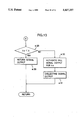
- FIG. 6 is a flow chart showing an outline of processing operations that the bill identification apparatus of the invention executes
- FIG. 7 is a flow chart showing a data fetch process
- FIG. 8 is a flow chart showing a data compression process
- FIG. 9 is a flow chart showing a decision data origination process
- FIG. 10 is a flow chart showing a decision process
- FIGS. 11 to 13 are continuations of the flow chart of FIG. 10.
- Each belt conveyor means comprises a driving timing pulley 2, a driven timing pulley 3, and a timing belt 4 passed around these pulleys.
- An inserted bill is transported by means of the driving timing pulleys 2 on both sides driven by a motor M.
- Symbol PC designates a pulse coder for outputting a rotation detection signal with every predetermined number of revolutions of the motor M.
- Symbols P0 to P3 designate transmission-type optical sensors which are each formed of a light emitting element and a photoelectric transducer disposed on either side of a bill transportation path on the plate 1.
- the sensors P0 to P3 output electrical signals corresponding to the volume of light transmitted through the inserted bill.
- Magnetic sensors P4 and P5 detect magnetic particulates contained in ink on the bill and outputting electrical signals. The bill is inserted and transported from left to right of FIG. 1.
- the respective photoelectric transducers of the sensors P0 to P3 are connected, through their corresponding preamplifiers 10 to 13 and A/D converters 20 to 23, to an input/output circuit 30 which is connected to a CPU 31.
- the output signals (see FIG. 4a) from the sensors P0 to P3 are amplified by means of the preamplifiers 10 to 13, respectively, converted into digital signals (see FIG. 4b), and applied to predetermined input ports of the input/output circuit 30.
- the sensors P4 and P5 are connected to the input/output circuit 30 through their corresponding preamplifiers 14 and 15 and waveform shaping circuits 24 and 25.
- the signals from the sensors P4 and P5 are amplified by means of the preamplifiers 14 and 15, respectively (see FIG. 4d), digitized by means of the waveform shaping circuits 24 and 25, respectively (see FIG. 4e), and applied to the input/output circuit 30. Every time a shaped waveform is applied to the input/output circuit 30, values in counters C1 and C2 in the circuit 30 are counted up automatically (see FIG. 4f). In response to a reset signal from the CPU 31, moreover, the counters C1 and C2 are reset automatically. The reset cycle of the counters C1 and C2 is equal to the output cycle of the rotation detection signal from the pulse coder PC.
- a memory 32 which comprises a RAM and a nonvolatile ROM, stores in a nonvolatile manner control programs associated with the sequence operation of a bill identification apparatus, decision on bills, etc. and various set data necessary for the decision on bills and the like.
- the set data for decision can be freely reloaded by operation through a manual data input device 33.
- the motor M as the drive source for the belt conveyor means, is operatively controlled by the CPU 31 through a motor driver circuit 26 and the input/output circuit 30.
- the rotation detection signals from the pulse coder PC are applied to the CPU 31 via the input/output circuit 30.
- An input/output interface 34 is used for the input and output of signals between the bill identification apparatus and an automatic vending machine, game machine, or the like which incorporates the identification apparatus.
- the CPU 31 concludes that the bill is inserted, and rotates the motor M forwardly, thereby starting to receive the inserted bill.
- the rotation detection signal which is delivered from the pulse coder PC with every predetermined number of revolutions of the motor M, the light transmission factor for a specific position on the inserted bill and the presence of the magnetic particulates therein are detected by means of the sensors P0 to P5.
- FIG. 4a is a diagram showing the transition (change of light transmission factor) of the electrical signal delivered from the sensor P0 when a leading end 100a of a bill 100, such as the one shown in FIG. 3, is inserted into the bill identification apparatus, with respect to an integrated value n (specific position on the inserted bill) of the frequency of delivery of the rotation detection signals from the pulse coder PC.
- the bill is inserted from left to right of FIG. 1, so that a light transmission factor for the leading-end side of the bill 100 shown in FIG. 3 corresponds to the left-hand end (with a smaller value for n) of the diagram of FIG.
- the distance between the respective positions on the bill in which the light transmission factors detected by the sensor P0 are read corresponds to the number of revolutions of the motor M which is equivalent to the transportation pitch for the bill.
- the position for a first data read cycle is determined depending on the insertion detection timings for the sensors P0 and P1 which function as bill insertion sensors.
- the authenticity and type of the inserted bill can be determined by previously storing a diagram form as an array (n, pcn) indicative of the relationship between values n for the integrated pulse number and detected values pcn, obtained when an authentic bill is inserted.
- the average of the values pcn corresponding to the individual values n is obtained by depositing a large number of authentic bills, and the average value, along with a tolerance , is previously stored as a criterion. Thereafter, the authenticity and type of each deposited bill are determined depending on whether or not all of detected values si associated with data (n, sn) detected from each bill are between pcn+ (upper limit value) and pcn-s (lower limit value).
- the difference between the upper and lower limit values as criteria must be set at a considerably small value, as shown in FIG. 5, for example. If the tolerance is too small, however, those authentic bills which cannot satisfy some of authenticity conditions due to partial soiling or the like may be rejected in some cases. Also, those authentic bills which are entirely soiled by long circulation so that their detected data values are uniformly shifted up or down may possibly be concluded to be false.
- the following processes are executed in order to prevent wrong decisions which are attributable to partial soiling of the bills, fluctuations of optical data caused by aging of the optical sensors or deterioration of the bills, etc.
- an appropriate discrimination process can be executed by comparing authentic standard data pci with a modified value pm.sn which is the product of the detected data sn detected from each position n for authenticity decision and the correction factor pm.
- a bill inspection section is divided into a plurality of subsections so that data obtained between the subsections are leveled to be detected data for each position (section), without using the data from the sensors P0 to P5 directly as data for the position.
- the deposition of the bill as an object of identification is completed as the rotation detection signals from the pulse coder PC are inputted for nmax number of pulses after the drive of the motor M is started for transportation.
- the correction factor pm is given by the following equation (2), and modified detected data for each detected data pi is represented by pm ⁇ ##EQU3##
- the deviation phi thus obtained is equivalent to a sample from a population which has a 0-average 1-variance standard normal distribution, and that the sum of the squares of the deviation complies with the ⁇ 2 distribution.
- the heterogeneity pr indicative of the correlation between the respective diagram forms of the modified detected data pm.pi and the authentic standard data pci according to the following equation (4), the heterogeneity pr complies with the ⁇ 2 distribution, and the value of modified detected data pm.pi for each position i pertains to the probability associated with the diagram form of the authentic standard data pci. ##EQU4##
- the respective values of correction factors pmj of the individual optical sensors Pj should be substantially equal to one another when an authentic bill is inserted.
- the general soiling of the bill cannot be regarded as uniform if the correction factors pmj of the individual sensors are subject to remarkable scattering.
- the scattering of the correction factors pmj of the individual sensors also constitutes an essential factor for the authenticity decision. This scattering of the correction factors may be determined on the basis of the difference between the maximum and minimum values of the correction factors of the sensors, for example.
- the scattering is estimated from the average of the correction factors and the standard deviation between the correction factors obtained when a number of authentic bills are inserted, as in the case based on equation (3).
- possible values for the correction factors pmj of the sensors Pj range from 0 to positive infinity, centering around 1, so that this distribution is transformed into a normal distribution covering values which range from negative infinity to positive infinity, centering around 0.
- the correction factors pmj of the individual sensors Pj are transformed into standardized correction factors zpmj according to the following equation (5), using standard deviations pmsj for the correction factors of the sensors Pj obtained when a number of authentic bills are inserted.
- pmss indicative of scattering of the correction factor distribution for the sensors Pj is computed according to the following equation (6).
- pmcx and pmsx are the average of the correction factors of the sensors Pj and the standard deviation of the correction factors, respectively, obtained when a number of authentic bills are tested.
- the root-signed term of equation (6) represents the correction factor deviation for each sensor for the subject bill.
- the scattering of the correction factor deviations for the sensors may be determined depending on whether or not the difference between the maximum and minimum values of the correction factors pmj is within its tolerance.
- FIG. 6 is a flow chart showing an outline of operation for the aforementioned processes executed by the CPU 31 for operatively controlling the bill identification apparatus according to the present embodiment.
- FIGS. 7 to 13 are flow chart schematically showing the principal parts of the processing operation. Referring now to these flow charts, the processing operation according to the present embodiment will be described.
- Step a1 When the light volumes detected by means of the sensors P0 and P1, which function as bill insertion sensors, are reduced in Step a1, the CPU 31 concludes that a bill is inserted, and then proceeds to Step a2.
- the CPU 31 initializes a counter n for integrating the rotation detection signals from the pulse coder PC, various temporary-storage registers in the memory 32, and the counters C1 and C2 in the input/output circuit 30. Then, in Step a3, the CPU 31 causes the motor M to rotate forwardly, thereby starting the operation of the timing belt 4 for transportation.
- the motor M rotates to transport a predetermined number of inserted bills
- the CPU 31 receives every rotation detection signal from the pulse coder PC as an interruption signal, and executes a data fetch process of Step a4, the principal part of which is shown in FIG. 7.
- the CPU 31 first determines, in Step b1, whether or not a value in the counter n for integrating the rotation detection signals from the pulse coder PC is greater than the set maximum value nmax, which is indicative of the number of pulses for the completion of the deposition of the bills.
- Step b2 If the value in the counter n is not greater than the set maximum value nmax, the CPU 31 proceeds to Step b2, whereupon it initializes a sensor selection index j at 0, and determines, in Step b3, whether or not the value of the index j is greater than a maximum value jmax corresponding to the number of sensors.
- Step b5 the CPU 31 selects an input port of the input/output circuit 30 in accordance with the value of the sensor selection index j, and reads current output values px(j) in the A/D converter 20, 21, 22 or 23 for one of the sensors Pj or a current integrated value px(j) in the counter C1 or C2.
- Step b6 After reading the output value or integrated value px(j), the CPU 31 proceeds to Step b6, whereupon it integratively stores one of array registers p(i, j) corresponding to the section name i or sensor name j with the value px(j) obtained in Step b5. Then, the CPU 31 increments the value of the index j in Step b7. Thereafter, the CPU 31 repeatedly executes the processes of Steps b3 to b7 in the same manner as described until the value of the index j exceeds the set maximum value jmax corresponding to the number of sensors, and detects and integratively stores data for the individual sensors Pj.
- the array registers p(i, j) are initialized in the aforementioned process of Step a2, and their initial values are all 0.
- the CPU 31 When the CPU 31 confirms that the value of the sensor selection index j is greater than the set maximum value jmax and that the addition of the detected data for the individual sensors Pj is completed, it divides the current value in the counter n by the set value pdev, which is indicative of the number of pulses corresponding to one section of the data detection region, and obtains the remaining integer (this process is represented by n MOD pdev in FIG. 7). Then, the CPU 31 determines whether or not the remaining integer is equal to pdev-1, that is, whether or not the data detection timing for the present cycle is one for the final or pdev'th cycle in the data detection region for the one section (Step b8).
- Step b11 the CPU 31 increments the value in the counter n, and suspends the data fetch process (Step b11). Every time the rotation detection signal from the pulse coder PC is inputted, thereafter, the CPU 31 repeatedly executes the processes of Steps b1 and b2, loop processes of Steps b3 to b7, and processes of Steps b8 and b11 in the same manner as described until the value in the counter n exceeds the set maximum value nmax, or the discrimination condition of Step b8 is satisfied.
- the integral value i obtained by dividing the current value in the counter n by the set value pdev in the process of Step b4 cannot be updated.
- the value for the section name i once computed is maintained until the processes of Steps b1 and b2, loop processes of Steps b3 to b7, and processes of Steps b8 and b11 are successively executed pdev number of times.
- the values px(j) detected with the pdev number of detection timings corresponding to each section of the data detection region are integrated and stored individually in (jmax+1) number of array registers p(i, j), which have the same section name i and different sensor names j. Then, the processes of Steps b1 and b2, loop processes of Steps b3 to b7, and processes of Steps b8 and b11 are successively executed pdev number of times.
- Step b9 Every time the remaining integer obtained by dividing the current value in the counter n by the set value pdev becomes equal to pdev-1 so that the decision in Step b8 is positive, the CPU 31 executes a data compression process (Step b9) and a decision data origination process (Step b10) corresponding to the section name i.
- Step b8 If it is concluded in the discrimination process of Step b8 that the data fetch process is continuously repeated pdev number of times, the CPU 31 first executes the data compression process of Step b9, the principal part of which is shown in FIG. 8, in order to level the optical data and magnetic data with every section i and compute the detected data for each section i.
- the CPU 31 initializes the value of the sensor selection index j in Step c1, and determines in Step c2 whether or not the value of the index j is greater than the maximum value jmax. If the value of the index j is not greater than the maximum value jmax, the CPU 31 proceeds to Step c3, whereupon it determines whether or not the current value of the index j is not greater than 3, that is, whether or not the index j indicates a value corresponding to one of the optical sensors.
- Step c4 If it is concluded that the current value of the index j is not greater than 3 and is indicative of one optical sensor, the CPU 31 proceeds to Step c4, whereupon it reads an integrated value stored in the array register p(i, j) corresponding to the section name i and sensor name j, and divides the integrated value by the set value pdev, thereby obtaining an average value equivalent to one detection timing for the sensor Pj in the data detection region corresponding to the section name i.
- the CPU 31 stores the array register p(i, j) for renewal with this average value as detected data for the optical sensor Pj in the section i (see FIG. 4c).
- Step c4 If it is concluded that the current value of the index j is not smaller than 4 and is indicative of one of the magnetic sensors, the process of Step c4 is not executed, and the integrated value stored in the array register p(i, j) is maintained as it is as detected data for the magnetic sensor Pj in the section i (see FIG. 4g).
- Step c5 the CPU 31 increments the value of the sensor selection index j, and then returns to the process of Step c2. Thereafter, the CPU 31 repeatedly executes the processes of Steps c2 to c5 in the same manner as described until the value of the index j exceeds jmax, and stores the array register p(i, j) with the detected data for each sensor Pj in the section i.
- the detected data in the register p(i, j) corresponds to each value pi in equation (2).
- the integrated value in the register p(i, j) is divided by pdev only if the index j corresponds to the value indicative of the optical sensor, and stores the register p(i, j) again with the resulting value as the detected data. Since the pdev number of cycles of detection in one section itself is helpful in leveling the data, the integrated value p(i, j) need not always be divided by pdev to obtain the average value. As in the case of the magnetic data, the integrated value p(i, j) itself can be used as the detected data by only properly setting set values for computations, decisions, etc.
- Step c2 If it is concluded in the discrimination process of Step c2 that jmax is exceeded by the value of the sensor selection index j or that the storage of the detected data for each sensor in the section i is completed, the CPU 31 finishes the data compression process, and then executes the decision data origination process of Step b10, the principal part of which is shown in FIG. 9.
- the CPU 31 first determines whether or not the current value of the index i indicative of the section name is between set values imin and imax, that is, whether or not an i'th section of the data detection region, indicated by the current value of the index i, is within a range such that it is regarded as an appropriate object of data detection for the authentication and classification of the bill (Step d1).
- Step d1 the processes of Steps d2 to d11, which are required for decision data origination, are not executed, and the CPU 31 proceeds to the process of Step b11 immediately after finishing the discrimination process of Step d1.
- Step d1 determines whether or not the value of the sensor selection index j is greater than the maximum value jmax.
- Each integrating register zp(j) is a register which is initialized in the aforementioned process of Step a2, and its initial value is 0.
- the process of Step d4 is a process which corresponds to ⁇ pi of equation (2), and the value ⁇ pi is the final value of the register zp(j).
- the CPU 31 sets an index k for specifying the types of the bills at the initial value 0 in Step d5, and determines in Step d6 whether or not the current value of the index k is greater than a set value kmax which corresponds to the number of types of the bills to be handled in the bill identification apparatus. If the value of the index k is not greater than the set value kmax, the CPU 31 proceeds to Step d7, whereupon it reads the respective values of standard data pc(i, j, k) and standard deviation ps(i, j, k) thereof from the nonvolatile RAM of the memory 32.
- the standard data pc(i, j, k) is the average of data obtained from the detection section i by testing a number of authentic bills of the type k by means of the sensors Pj.
- the standard deviation ps(i, j, k) is indicative of scattering of the data obtained from the detection section.
- the CPU 31 executes an operational expression [p(i, j)/ps(i, j, k)] 2 in Step d8, on the basis of the value of the data p(i, j) detected from the detection sections i of the currently deposited bill by means of the sensors Pj and the value Ds(i, j, k), and integratively stores an integrating register zps(j, k) with the resulting value.
- Step d9 the CPU 31 executes an operational expression p(i, j).pc(i, j, k)/ps(i, j, k) 2 on the basis of the value of the detected data p(i, j) and the values of the standard data pc(i, j, k) and the standard deviation ps(i, j, k) thereof, and integratively stores an integrating register zcps(j, k) with the resulting value.
- Each of the registers zps(j, k) and zcps(j, k) is initialized in the aforementioned process of Step a2, and its initial value is 0.
- Steps d8 and d9 are processes for obtaining values corresponding to the terms ⁇ (pi/psi) 2 and ⁇ (pi.pci)/psi 2 ⁇ of equation (4), respectively.
- ⁇ (pi/psi) 2 and ⁇ (pi.pci)/psi 2 ⁇ of equation (4) are the final values of the registers zps(j, k) and zcps(j, k), respectively.
- the CPU 31 increments the value of the index k for specifying the bill type in Step d10. Thereafter, the CPU 31 repeatedly executes the processes of Steps d8 to d10 in the same manner as described until the value of the index k exceeds the value kmax for the number of types of the bills to be handled in the bill identification apparatus.
- Step d6 If it is concluded in the process of Step d6 that the value of the index k is greater than the bill type number kmax or that the integral data ⁇ (pi/psi) 2 and ⁇ (pi.pci)/psi 2 ⁇ , computed for the sensor Pj specified by the current value of the index j, in accordance with the standard data for each bill type, are stored for renewal, the CPU 31 proceeds to Step d11, whereupon it increments the value of the sensor selection index j for specifying the sensor. Thereafter, the CPU 31 repeatedly executes the processes of Steps d3 to d11 in the same manner as described until the value of the index j exceeds jmax.
- Step d3 If it is then concluded in the discrimination process of Step d3 that the value of the index j for specifying the sensor is greater than the set maximum value jmax corresponding to the number of sensors and the like or that the integration of various data for all the combinations of the sensors Pj of the bill identification apparatus and the bill types is finished, the CPU 31 finishes the decision data origination process and proceeds to Step b11.
- Step b11 the CPU 31 increments the value in the counter n, and executes again the data fetch process shown in FIG. 7 from the beginning, in response to the next rotation detection signal from the pulse coder PC.
- This data fetch process is repeatedly executed every time the rotation detection signal from the pulse coder PC is inputted before nmax is exceeded by the value in the counter n.
- Step b1 If it is concluded in the discrimination process of Step b1 that the set value nmax for bill deposition is exceeded by the value in .the counter n as the data fetch process is repeatedly executed or that the bills are delivered to a discrimination position (where it is determined whether the bills should be deposited or returned after bill data detection), the CPU 31 proceeds to Step at, whereupon it stops the drive of the motor M to suspend the transportation of the bills. Then, the CPU 31 proceeds to the discrimination process of Step a6, the principal part of which is shown in FIGS. 10 to 13.
- the CPU 31 When the discrimination process is started, the CPU 31 first sets the index k for specifying the types of the bills at the initial value 0 in Step e1, and determines in Step d8 whether or not the current value of the index k is greater than the set value kmax which corresponds to the number of types of the bills to be handled in the bill identification apparatus. If the value of the index k is not greater than the set value kmax, the CPU 31 then executes a process for determining the authenticity and type of the bills on the basis of the standard data for each bill type k and sensor type j.
- the CPU 31 initializes the sensor selection index j in Step e3, and then determines in Step e4 whether or not the value of the index j is greater than the maximum value jmax. If the value of the index j is not greater than jmax, the CPU proceeds to Step e5, whereupon it reads and temporarily stores the following data from the data previously stored in the nonvolatile RAM of the memory
- Step e6 the CPU 31 obtains the correction factors of the sensors Pj for the bill type k by dividing the value of the standard data integrated value zpc(j, k) by the value in the sensor-classified detected data integrating register zp(j), obtained by integrating the detected data from the sensors Pj throughout the range from imin to imax, and stores a correction factor storage register zpm1 with the resulting value.
- the process of Step e6 is an arithmetic process corresponding to equation (2).
- the CPU 31 executes an operational expression corresponding to equation (4) in Step e7.
- the CPU 31 executes the operational expression on the basis of the value in the correction factor storage register zpm1 corresponding to ⁇ pci/ ⁇ pi, which is obtained in Step e6, the value in the integrating register zps(j, k) corresponding to ⁇ (pi/psi) 2 which is obtained in the process of Step d8, the value in the integrating register zcps(j, k) corresponding to ⁇ (pi-pci)/psi 2 ⁇ , which is obtained in the process of Step d9, and the standard deviation integrated value zcs(j, k) for standard data corresponding to ⁇ (pi/psi) 2 , which is read in Step e5.
- the CPU 31 obtains the heterogeneity pr of each sensor Pj for the bill type k, and stores a heterogeneity storage register zpr with this value. Then, in Step e8, the CPU 31 executes an operational expression corresponding to equation (5) by taking a logarithm of the correction factor zpm1 of each sensor Pj for the bill type k and dividing the logarithm by the correction factor standard deviation pms(j, k) of the sensor Pj for the bill type k. Thus, the CPU 31 obtains a standardized correction factor by converting the correction factor zpm1 into normal distribution, and stores a storage register zpm2 with the obtained correction factor. In Step e9, moreover, the CPU 31 takes the absolute value of zpm2 for comparison, and temporarily stores a register xpm with it.
- Step e10 the CPU 31 determines whether or not the absolute value xpm of the standardized correction factor zpm2 is greater than the correction factor scattering criterion value xsigm, that is, whether or not to conclude that the deposited bill is not of the type k in accordance with the standardized correction factor based on the detected data obtained from the currently deposited bill by means of the sensors Pj.
- Step e11 If it is concluded that the absolute value of the standardized correction factor zpm2 is greater than the correction factor scattering criterion value xsigm or that the bill is not of the type k, the CPU 31 proceeds to Step e11, whereupon it sets 1 in a rejection condition register R1(k) for recording that the deposited bill is not of the type k, and records that the lately deposited bill is not of the type k. If it is concluded that the absolute value of the standardized correction factor zpm2 is smaller than the correction factor scattering criterion value xsigm, the current value in the register R1(k) is retained as it is. Each rejection condition register R1(k) is initialized in the aforementioned process of Step a2, and its initial value is 0.
- Step e12 the CPU 31 determines whether or not the value of the heterogeneity (zpr) obtained in Step e7 is greater than the heterogeneity criterion value xkais, that is, whether or not to conclude that the deposited bill is not of the type k in accordance with the heterogeneity based on the detected data obtained from the currently deposited bill by means of the sensors Pj.
- the CPU 31 proceeds to Step e13, whereupon it sets 1 in the rejection condition register R1(k) for recording that the deposited bill is not of the type k, and records that the lately deposited bill is not of the type k. If it is concluded that the value of the heterogeneity zpr is smaller than the heterogeneity criterion value xkais, the current value in the register R1(k) is retained as it is.
- Step e14 the CPU 31 integratively stores a linear correction factor function integrating register ypm(k) for each bill type k with the value of the standardized correction factor zpm2 obtained in the process of Step e8.
- Step e15 the CPU 31 integratively stores a quadratic correction factor function integrating register zpm(k) for each bill type k with the square of the standardized correction factor zpm2.
- Each of the linear and quadratic correction factor function integrating registers ypm(k) and zpm(k) is initialized in the aforementioned process of Step a2, and its initial value is 0.
- the process of Step e14 is a process for integrating values of the standardized correction factor zpm2 corresponding to zpmj of equations (5) and (8), thereby obtaining a value corresponding to ⁇ zpmj of equation (8).
- ⁇ zpmj of equation (8) is the final value of the register ypm(k).
- the process of Step e15 is a process for integrating values zpm2 2 corresponding to zpmj 2 of equation (6), thereby obtaining a value corresponding to ⁇ zpmj 2 of equation (8).
- ⁇ zpmj 2 of equation (8) is the final value of the register zpm(k).
- Step e16 the CPU 31 integratively stores an overall heterogeneity storage register zpr(k) for each bill type k with the value of the heterogeneity (zpr) obtained in the process of Step e7.
- Step e17 moreover, the CPU 31 increments the value of the sensor selection index j, and then returns to the process of Step e4.
- Each overall heterogeneity storage register zpr(k) is initialized in the aforementioned process of Step a2, and its initial value is 0.
- the CPU 31 repeatedly executes the processes of Steps e4 to e17 in the same manner as described until the value of the sensor selection index j exceeds the maximum value jmax. Then, the CPU 31 determines whether or not it is appropriate to recognize that the currently deposited bill, as an object of decision, is of the type specified by the index k, in accordance with the criterion data previously stored in the nonvolatile RAM of the memory 32, corresponding to the combination of the bill type indicated by the index k and each sensor Pj.
- the criterion data include the standard data integrated value zpc(j, k), standard deviation integrated value zcs(j, k) for standard data, correction factor standard deviation pms(j, k), correction factor scattering criterion value xsigm common to individual combinations, and heterogeneity criterion value xkais.
- the values corresponding to ⁇ zpmj and ⁇ zpmj 2 of equation (6) is loaded into the registers ypm(k) and zpm(k), respectively, in the finally executed processes of Steps e14 and e15.
- the register zpr(k) is loaded with the overall heterogeneity as an integrated value of the heterogeneities computed according to the data obtained from the individual sensors Pj (Step e16), and the value of the sensor selection index j is inched to jmax+i (Step e17).
- Step e18 the CPU 31 executes an operational expression corresponding to equation (8) on the basis of the values in the registers ypm(k) and zpm(k), which correspond to ⁇ zpmj and ⁇ zpmj 2 of equation (8), respectively, and the set values pmcx(k) and pmsx(k) corresponding to pmcx and pmsx of equation (6), respectively, and read in Step e5, thereby computing a value indicative of scattering of the correction factor of each sensor on the assumption that the deposited bill as the object of decision is of the type k.
- Step e19 the CPU 31 determines whether or not the value in the register pm(k) is greater than the correction factor scattering criterion value xsigm, that is, whether or not the assumption that the deposited bill is of the type k is appropriate. If it is concluded that the value in the register pm(k) is greater than the criterion value xsigm or that the assumption that the deposited bill is of the type k is wrong, the CPU 31 proceeds to Step e20, whereupon it sets 1 in the rejection condition register R1(k) for recording that the deposited bill is not of the type k.
- Step e21 the CPU 31 determines whether or not the value of the overall heterogeneity zpr(k) is greater than the overall heterogeneity criterion value xkait, that is, whether or not it is appropriate to recognize that the deposited bill is of the type k.
- the CPU 31 proceeds to Step e22, whereupon it sets 1 in the rejection condition register R1(k). If it is concluded that the value zpr(k) is smaller than xkait, the current value in the register R1(k) is retained as it is.
- Step e23 the CPU 31 determines whether or not the lately computed value of the overall heterogeneity zpr(k) is smaller than a current value in a minimum heterogeneity storage register parks.
- the register parks is initialized in the aforementioned process of Step e2, and its initial value is positive infinity (maximum settable value). If it is concluded that the lately computed value of the overall heterogeneity zpr(k) is smaller than the current value in the register parks, the CPU 31 proceeds to Step e24, whereupon it determines whether or not 0 is set in the rejection condition register R1(k), that is, whether or not it has already been concluded that it is appropriate to recognize that the currently deposited bill is of the type k.
- the CPU 31 stores the register parks for renewal with the lately computed value of the overall heterogeneity zpr(k) as a minimum overall heterogeneity value in Step e25.
- the CPU 31 stores an authentic bill type candidate storage register ks with the bill type k for renewal.
- the register ks is initialized in the aforementioned process of Step a2, and its initial value is negative infinity (at least smaller than zero).
- Step e23 or e24 if the decision in Step e23 or e24 is negative, that is, if it is concluded that the lately computed value of the overall heterogeneity zpr(k) is greater than the current value in the register parks, the processes of Steps e25 and e26 are not executed, and the CPU 31 retains the current values in the minimum heterogeneity storage register parks and the authentic bill type candidate storage register ks as they are. This is also done when it has already been concluded that it is inappropriate to recognize that the currently deposited bill is of the type k, even though it is concluded that the lately computed value of the overall heterogeneity zpr(k) is smaller than the current value in the register parks.
- Step e27 the CPU 31 increments the value of the index k for specifying the bill type in Step e27, and then proceeds to the process of Step e2.
- the CPU 31 repeatedly executes the processes of Steps e2 to e27 for the newly specified bill type k in the same manner as described until the value of the index k exceeds the set value kmax corresponding to the number of types of the bills to be handled in the bill identification apparatus.
- the CPU 31 stores the minimum heterogeneity storage register parks and the authentic bill type candidate storage register ks with the value of the overall heterogeneity zpr(k) and the bill type k, respectively, for renewal (Steps e25 and e26), provided that the overall heterogeneity zpr(k), obtained on the assumption that the currently deposited bill is of the type k, is smaller than the minimum heterogeneity value parks computed so far (or initialized) and that it is concluded that it is appropriate to recognize that the currently deposited bill is of the type k (Steps e23 and e24).
- the register ks stores the value k corresponding to the bill type with which the value of the overall heterogeneity zpr(k), as compared with the currently deposited bill, is the smallest, among other bill types with which i is not set in their corresponding rejection condition registers R1(k).
- Step e28 determines whether or not the value in the authentic bill type candidate storage register ks is smaller than 0. If the value in the register ks is smaller than 0, then it indicates that the decision in Step e24 has no opportunity at all to be positive, and that there is not any bill type indicated by the rejection condition register R1(k) which is not set to 1, that is, the currently deposited bill is false.
- the CPU 31 proceeds to Step e29, whereupon it outputs a return signal, and then proceeds to Step a7 to execute a return process for the bill. If the value in the authentic bill type candidate storage register ks is not smaller than 0, then it indicates that the register ks is stored with the value k corresponding to the bill type with which the value of the overall heterogeneity zpr(k), as compared with the currently deposited bill, is the smallest, among other bill types with which 1 is not set in their corresponding rejection condition registers R1(k). Accordingly, the CPU 31 proceeds to Step e30, whereupon it outputs an authentic bill signal corresponding to one of the bill types stored in the register ks. After outputting a bill collecting signal for collecting the bill in the bill identification apparatus in Step e31, the CPU 31 proceeds to Step a7, whereupon it executes a collecting process for the bill.
- the detected data pi are corrected by means of the correction value pm, and the authentication is effected by comparing the corrected detected data pm.pi and the standard pattern value pci.
- the authenticity of the bills can be discriminated without any fluctuations of the data attributable to general deterioration or soiling of the bills or detecting means.
- the authenticity and type of the bills are discriminated by computing the heterogeneity pr on the basis of a statistical synthetic evaluation of the correlation between the standard pattern value pci and the detected data pi for each detection position i. Even if the bills are subject partial soiling or the like, therefore, the decision cannot be substantially affected by partial data errors. Thus, the reliability of the authentication and classification of the bills can be further improved.
- the data required for the computation of the correction value pm and the heterogeneity pr are gradually updated by means of correction value computing means and heterogeneity computing means every time the detecting means detects the characteristic data pi, so that the detected data pi need not be stored in large numbers in the memory, and a large number of stored data need not be processed en bloc.
- the memory capacity of the memory means can be saved, and the load on the arithmetic processing means, such as the correction value and heterogeneity computing means, can be reduced.
Landscapes
- Physics & Mathematics (AREA)
- General Physics & Mathematics (AREA)
- Health & Medical Sciences (AREA)
- General Health & Medical Sciences (AREA)
- Toxicology (AREA)
- Inspection Of Paper Currency And Valuable Securities (AREA)
Abstract
Description
phi=(pm.pi-pci)/psi (3)
phi=(pm.pi-pci)/psi (3)
zpmj=(LOG pmj)/pmsj (5)
Claims (9)
pr=pm.sup.2.Σ(pi/psi).sup.2 -2.pm.Σ(pi.pci/psi.sup.2) +Σ(pci/psi).sup.2
Applications Claiming Priority (2)
| Application Number | Priority Date | Filing Date | Title |
|---|---|---|---|
| JP4-358125 | 1992-12-25 | ||
| JP04358125A JP3105679B2 (en) | 1992-12-25 | 1992-12-25 | Banknote recognition device |
Publications (1)
| Publication Number | Publication Date |
|---|---|
| US5437357A true US5437357A (en) | 1995-08-01 |
Family
ID=18457678
Family Applications (1)
| Application Number | Title | Priority Date | Filing Date |
|---|---|---|---|
| US08/170,402 Expired - Fee Related US5437357A (en) | 1992-12-25 | 1993-12-20 | Bill identification apparatus |
Country Status (3)
| Country | Link |
|---|---|
| US (1) | US5437357A (en) |
| JP (1) | JP3105679B2 (en) |
| KR (1) | KR100285133B1 (en) |
Cited By (80)
| Publication number | Priority date | Publication date | Assignee | Title |
|---|---|---|---|---|
| US5542518A (en) * | 1994-05-25 | 1996-08-06 | Toyo Communication Equipment Co., Ltd. | Method of identifying the denominations of pieces of paper |
| US5633949A (en) * | 1990-02-05 | 1997-05-27 | Cummins-Allison Corp. | Method and apparatus for currency discrimination |
| US5790245A (en) * | 1995-05-01 | 1998-08-04 | Nippon Conlux Co., Ltd. | Paper examining method and apparatus |
| US5790697A (en) | 1990-02-05 | 1998-08-04 | Cummins-Allion Corp. | Method and apparatus for discriminating and counting documents |
| US5806650A (en) * | 1994-11-14 | 1998-09-15 | Cummins-Allison Corp. | Currency discriminator having a jam detection and clearing mechanism and method of clearing a jam |
| US5815592A (en) | 1990-02-05 | 1998-09-29 | Cummins-Allison Corp. | Method and apparatus for discriminating and counting documents |
| US5870487A (en) * | 1990-02-05 | 1999-02-09 | Cummins-Allison Corp. | Method and apparatus for discriminting and counting documents |
| US5923413A (en) | 1996-11-15 | 1999-07-13 | Interbold | Universal bank note denominator and validator |
| US5940623A (en) | 1997-08-01 | 1999-08-17 | Cummins-Allison Corp. | Software loading system for a coin wrapper |
| WO1999050796A1 (en) * | 1998-03-31 | 1999-10-07 | De La Rue International Ltd. | Methods and apparatus for monitoring articles |
| US5966456A (en) | 1990-02-05 | 1999-10-12 | Cummins-Allison Corp. | Method and apparatus for discriminating and counting documents |
| US5970165A (en) * | 1995-03-06 | 1999-10-19 | Kabushiki Kaisha Nippon Conlux | Paper discriminating device including peak counting and analysis |
| US6039645A (en) | 1997-06-24 | 2000-03-21 | Cummins-Allison Corp. | Software loading system for a coin sorter |
| US6078683A (en) * | 1997-11-20 | 2000-06-20 | De La Rue, Inc. | Method and system for recognition of currency by denomination |
| US6091844A (en) * | 1993-10-14 | 2000-07-18 | Omron Corporation | Image processing device and method for identifying an input image and copier including same |
| EP0987658A4 (en) * | 1998-04-01 | 2000-11-08 | Nippon Conlux Co Ltd | Method and apparatus for processing paper money |
| US6220419B1 (en) | 1994-03-08 | 2001-04-24 | Cummins-Allison | Method and apparatus for discriminating and counting documents |
| US6234294B1 (en) | 1998-10-29 | 2001-05-22 | De La Rue International Ltd | Method and system for recognition of currency by denomination |
| US6278795B1 (en) | 1995-12-15 | 2001-08-21 | Cummins-Allison Corp. | Multi-pocket currency discriminator |
| US6311819B1 (en) | 1996-05-29 | 2001-11-06 | Cummins-Allison Corp. | Method and apparatus for document processing |
| US6318537B1 (en) | 1999-04-28 | 2001-11-20 | Cummins-Allison Corp. | Currency processing machine with multiple internal coin receptacles |
| US6363164B1 (en) | 1996-05-13 | 2002-03-26 | Cummins-Allison Corp. | Automated document processing system using full image scanning |
| US20020039206A1 (en) * | 2000-10-03 | 2002-04-04 | Masanori Mukai | Paper discriminator |
| US6393140B1 (en) * | 1997-04-16 | 2002-05-21 | Nippon Conlux Co., Ltd. | Paper-like piece identifying method and device |
| US6398000B1 (en) | 2000-02-11 | 2002-06-04 | Cummins-Allison Corp. | Currency handling system having multiple output receptacles |
| US20030015396A1 (en) * | 2001-04-18 | 2003-01-23 | Mennie Douglas U. | Method and apparatus for discriminating and counting documents |
| US6573983B1 (en) | 1996-11-15 | 2003-06-03 | Diebold, Incorporated | Apparatus and method for processing bank notes and other documents in an automated banking machine |
| US20030108233A1 (en) * | 1990-02-05 | 2003-06-12 | Raterman Donald E. | Method and apparatus for currency discrimination and counting |
| US6588569B1 (en) | 2000-02-11 | 2003-07-08 | Cummins-Allison Corp. | Currency handling system having multiple output receptacles |
| US6601687B1 (en) | 2000-02-11 | 2003-08-05 | Cummins-Allison Corp. | Currency handling system having multiple output receptacles |
| US6637576B1 (en) | 1999-04-28 | 2003-10-28 | Cummins-Allison Corp. | Currency processing machine with multiple internal coin receptacles |
| US6661910B2 (en) | 1997-04-14 | 2003-12-09 | Cummins-Allison Corp. | Network for transporting and processing images in real time |
| US6778693B2 (en) | 1995-05-02 | 2004-08-17 | Cummins-Allison Corp. | Automatic currency processing system having ticket redemption module |
| EP1494178A1 (en) * | 2003-06-30 | 2005-01-05 | Asahi Seiko Kabushiki Kaisha | A banknote validator with a reflecting optical sensor |
| US6843418B2 (en) | 2002-07-23 | 2005-01-18 | Cummin-Allison Corp. | System and method for processing currency bills and documents bearing barcodes in a document processing device |
| US6860375B2 (en) | 1996-05-29 | 2005-03-01 | Cummins-Allison Corporation | Multiple pocket currency bill processing device and method |
| US6866134B2 (en) | 1992-05-19 | 2005-03-15 | Cummins-Allison Corp. | Method and apparatus for document processing |
| US6880692B1 (en) | 1995-12-15 | 2005-04-19 | Cummins-Allison Corp. | Method and apparatus for document processing |
| US6957733B2 (en) | 1995-12-15 | 2005-10-25 | Cummins-Allison Corp. | Method and apparatus for document processing |
| US6959800B1 (en) | 1995-12-15 | 2005-11-01 | Cummins-Allison Corp. | Method for document processing |
| US6980684B1 (en) | 1994-04-12 | 2005-12-27 | Cummins-Allison Corp. | Method and apparatus for discriminating and counting documents |
| US7000828B2 (en) | 2001-04-10 | 2006-02-21 | Cummins-Allison Corp. | Remote automated document processing system |
| US7016767B2 (en) | 2003-09-15 | 2006-03-21 | Cummins-Allison Corp. | System and method for processing currency and identification cards in a document processing device |
| US7158662B2 (en) | 2002-03-25 | 2007-01-02 | Cummins-Allison Corp. | Currency bill and coin processing system |
| US7187795B2 (en) | 2001-09-27 | 2007-03-06 | Cummins-Allison Corp. | Document processing system using full image scanning |
| US7232024B2 (en) | 1996-05-29 | 2007-06-19 | Cunnins-Allison Corp. | Currency processing device |
| US7269279B2 (en) | 2002-03-25 | 2007-09-11 | Cummins-Allison Corp. | Currency bill and coin processing system |
| US7513417B2 (en) | 1996-11-15 | 2009-04-07 | Diebold, Incorporated | Automated banking machine |
| US7551764B2 (en) | 2002-03-25 | 2009-06-23 | Cummins-Allison Corp. | Currency bill and coin processing system |
| US7559460B2 (en) | 1996-11-15 | 2009-07-14 | Diebold Incorporated | Automated banking machine |
| US7584883B2 (en) | 1996-11-15 | 2009-09-08 | Diebold, Incorporated | Check cashing automated banking machine |
| US7619721B2 (en) | 1996-11-27 | 2009-11-17 | Cummins-Allison Corp. | Automated document processing system using full image scanning |
| US7647275B2 (en) | 2001-07-05 | 2010-01-12 | Cummins-Allison Corp. | Automated payment system and method |
| EP2199986A1 (en) * | 2008-12-22 | 2010-06-23 | Giesecke & Devrient GmbH | Method and device for recognising optical characteristics of a valuable document |
| US20110019900A1 (en) * | 2008-03-19 | 2011-01-27 | Universal Entertainment Corporation | Device for processing paper sheets or the like |
| US7903863B2 (en) | 2001-09-27 | 2011-03-08 | Cummins-Allison Corp. | Currency bill tracking system |
| US7929749B1 (en) | 2006-09-25 | 2011-04-19 | Cummins-Allison Corp. | System and method for saving statistical data of currency bills in a currency processing device |
| US7946406B2 (en) | 2005-11-12 | 2011-05-24 | Cummins-Allison Corp. | Coin processing device having a moveable coin receptacle station |
| US7980378B2 (en) | 2006-03-23 | 2011-07-19 | Cummins-Allison Corporation | Systems, apparatus, and methods for currency processing control and redemption |
| US8162125B1 (en) | 1996-05-29 | 2012-04-24 | Cummins-Allison Corp. | Apparatus and system for imaging currency bills and financial documents and method for using the same |
| US8204293B2 (en) | 2007-03-09 | 2012-06-19 | Cummins-Allison Corp. | Document imaging and processing system |
| US8391583B1 (en) | 2009-04-15 | 2013-03-05 | Cummins-Allison Corp. | Apparatus and system for imaging currency bills and financial documents and method for using the same |
| US8417017B1 (en) | 2007-03-09 | 2013-04-09 | Cummins-Allison Corp. | Apparatus and system for imaging currency bills and financial documents and method for using the same |
| US8428332B1 (en) | 2001-09-27 | 2013-04-23 | Cummins-Allison Corp. | Apparatus and system for imaging currency bills and financial documents and method for using the same |
| US8433123B1 (en) | 2001-09-27 | 2013-04-30 | Cummins-Allison Corp. | Apparatus and system for imaging currency bills and financial documents and method for using the same |
| US8437529B1 (en) | 2001-09-27 | 2013-05-07 | Cummins-Allison Corp. | Apparatus and system for imaging currency bills and financial documents and method for using the same |
| US8437530B1 (en) | 2001-09-27 | 2013-05-07 | Cummins-Allison Corp. | Apparatus and system for imaging currency bills and financial documents and method for using the same |
| US8437532B1 (en) | 2009-04-15 | 2013-05-07 | Cummins-Allison Corp. | Apparatus and system for imaging currency bills and financial documents and method for using the same |
| USRE44252E1 (en) | 2002-01-10 | 2013-06-04 | Cummins-Allison Corp. | Coin redemption system |
| US8459436B2 (en) | 2008-10-29 | 2013-06-11 | Cummins-Allison Corp. | System and method for processing currency bills and tickets |
| US8478020B1 (en) | 1996-11-27 | 2013-07-02 | Cummins-Allison Corp. | Apparatus and system for imaging currency bills and financial documents and method for using the same |
| US8538123B1 (en) | 2007-03-09 | 2013-09-17 | Cummins-Allison Corp. | Apparatus and system for imaging currency bills and financial documents and method for using the same |
| US8627939B1 (en) | 2002-09-25 | 2014-01-14 | Cummins-Allison Corp. | Apparatus and system for imaging currency bills and financial documents and method for using the same |
| US8929640B1 (en) | 2009-04-15 | 2015-01-06 | Cummins-Allison Corp. | Apparatus and system for imaging currency bills and financial documents and method for using the same |
| US8944234B1 (en) | 2001-09-27 | 2015-02-03 | Cummins-Allison Corp. | Apparatus and system for imaging currency bills and financial documents and method for using the same |
| US8950566B2 (en) | 1996-05-13 | 2015-02-10 | Cummins Allison Corp. | Apparatus, system and method for coin exchange |
| US9141876B1 (en) | 2013-02-22 | 2015-09-22 | Cummins-Allison Corp. | Apparatus and system for processing currency bills and financial documents and method for using the same |
| US20150279140A1 (en) * | 2014-03-25 | 2015-10-01 | Ncr Corporation | Media item validation |
| US9818249B1 (en) | 2002-09-04 | 2017-11-14 | Copilot Ventures Fund Iii Llc | Authentication method and system |
| US20180247308A1 (en) * | 2017-02-27 | 2018-08-30 | Ncr Corporation | Validation of damaged banknotes |
Families Citing this family (3)
| Publication number | Priority date | Publication date | Assignee | Title |
|---|---|---|---|---|
| US8055063B2 (en) | 2003-09-30 | 2011-11-08 | Sharp Laboratories Of America, Inc. | Methods and systems for improving robustness of color balance correction |
| JP2005190473A (en) * | 2003-12-05 | 2005-07-14 | Sharp Corp | System and method for illuminant model estimation |
| JP4634073B2 (en) * | 2004-06-29 | 2011-02-16 | マミヤ・オーピー株式会社 | Paper sheet identification device and identification method |
Citations (8)
| Publication number | Priority date | Publication date | Assignee | Title |
|---|---|---|---|---|
| JPS589990A (en) * | 1981-04-10 | 1983-01-20 | クロエ・シミ | Cathode assembly for electrolytic cell |
| JPS6326918A (en) * | 1986-07-17 | 1988-02-04 | 有限会社オリエント | Temperature fuse |
| JPS645354A (en) * | 1987-06-25 | 1989-01-10 | Matsushita Electric Works Ltd | Load controller |
| JPH02148383A (en) * | 1988-11-30 | 1990-06-07 | Fuji Electric Co Ltd | Method of discriminating paper money |
| EP0477711A2 (en) * | 1990-09-27 | 1992-04-01 | Oki Electric Industry Company, Limited | Bill examination device |
| US5199543A (en) * | 1990-08-22 | 1993-04-06 | Oki Electric Industry Co., Ltd. | Apparatus for and method of discriminating bill |
| US5242041A (en) * | 1990-07-19 | 1993-09-07 | Japan Cash Machine Co., Ltd. | Apparatus for currency validation |
| US5301786A (en) * | 1989-06-19 | 1994-04-12 | Nippon Conlux Co., Ltd. | Method and apparatus for validating a paper-like piece |
-
1992
- 1992-12-25 JP JP04358125A patent/JP3105679B2/en not_active Expired - Fee Related
-
1993
- 1993-12-17 KR KR1019930028152A patent/KR100285133B1/en not_active Expired - Fee Related
- 1993-12-20 US US08/170,402 patent/US5437357A/en not_active Expired - Fee Related
Patent Citations (8)
| Publication number | Priority date | Publication date | Assignee | Title |
|---|---|---|---|---|
| JPS589990A (en) * | 1981-04-10 | 1983-01-20 | クロエ・シミ | Cathode assembly for electrolytic cell |
| JPS6326918A (en) * | 1986-07-17 | 1988-02-04 | 有限会社オリエント | Temperature fuse |
| JPS645354A (en) * | 1987-06-25 | 1989-01-10 | Matsushita Electric Works Ltd | Load controller |
| JPH02148383A (en) * | 1988-11-30 | 1990-06-07 | Fuji Electric Co Ltd | Method of discriminating paper money |
| US5301786A (en) * | 1989-06-19 | 1994-04-12 | Nippon Conlux Co., Ltd. | Method and apparatus for validating a paper-like piece |
| US5242041A (en) * | 1990-07-19 | 1993-09-07 | Japan Cash Machine Co., Ltd. | Apparatus for currency validation |
| US5199543A (en) * | 1990-08-22 | 1993-04-06 | Oki Electric Industry Co., Ltd. | Apparatus for and method of discriminating bill |
| EP0477711A2 (en) * | 1990-09-27 | 1992-04-01 | Oki Electric Industry Company, Limited | Bill examination device |
Cited By (170)
| Publication number | Priority date | Publication date | Assignee | Title |
|---|---|---|---|---|
| US5966456A (en) | 1990-02-05 | 1999-10-12 | Cummins-Allison Corp. | Method and apparatus for discriminating and counting documents |
| US6351551B1 (en) | 1990-02-05 | 2002-02-26 | Cummins-Allison Corp. | Method and apparatus for discriminating and counting document |
| US7536046B2 (en) | 1990-02-05 | 2009-05-19 | Cummins-Allison Corp. | Method and apparatus for currency discrimination and counting |
| US5790697A (en) | 1990-02-05 | 1998-08-04 | Cummins-Allion Corp. | Method and apparatus for discriminating and counting documents |
| US20030108233A1 (en) * | 1990-02-05 | 2003-06-12 | Raterman Donald E. | Method and apparatus for currency discrimination and counting |
| US5815592A (en) | 1990-02-05 | 1998-09-29 | Cummins-Allison Corp. | Method and apparatus for discriminating and counting documents |
| US20050117791A2 (en) * | 1990-02-05 | 2005-06-02 | Cummins-Allison Corp. | Method and apparatus for currency discrimination and counting |
| US5870487A (en) * | 1990-02-05 | 1999-02-09 | Cummins-Allison Corp. | Method and apparatus for discriminting and counting documents |
| US5912982A (en) * | 1990-02-05 | 1999-06-15 | Cummins-Allison Corp. | Method and apparatus for discriminating and counting documents |
| US7672499B2 (en) | 1990-02-05 | 2010-03-02 | Cummins-Allison Corp. | Method and apparatus for currency discrimination and counting |
| US5633949A (en) * | 1990-02-05 | 1997-05-27 | Cummins-Allison Corp. | Method and apparatus for currency discrimination |
| US5822448A (en) * | 1990-02-05 | 1998-10-13 | Cummins-Allison Corp. | Method and apparatus for currency discrimination |
| US6866134B2 (en) | 1992-05-19 | 2005-03-15 | Cummins-Allison Corp. | Method and apparatus for document processing |
| US6091844A (en) * | 1993-10-14 | 2000-07-18 | Omron Corporation | Image processing device and method for identifying an input image and copier including same |
| US6378683B2 (en) | 1994-03-08 | 2002-04-30 | Cummins-Allison Corp. | Method and apparatus for discriminating and counting documents |
| US6220419B1 (en) | 1994-03-08 | 2001-04-24 | Cummins-Allison | Method and apparatus for discriminating and counting documents |
| US7817842B2 (en) * | 1994-03-08 | 2010-10-19 | Cummins-Allison Corp. | Method and apparatus for discriminating and counting documents |
| US6980684B1 (en) | 1994-04-12 | 2005-12-27 | Cummins-Allison Corp. | Method and apparatus for discriminating and counting documents |
| US5542518A (en) * | 1994-05-25 | 1996-08-06 | Toyo Communication Equipment Co., Ltd. | Method of identifying the denominations of pieces of paper |
| US5806650A (en) * | 1994-11-14 | 1998-09-15 | Cummins-Allison Corp. | Currency discriminator having a jam detection and clearing mechanism and method of clearing a jam |
| US5970165A (en) * | 1995-03-06 | 1999-10-19 | Kabushiki Kaisha Nippon Conlux | Paper discriminating device including peak counting and analysis |
| US5790245A (en) * | 1995-05-01 | 1998-08-04 | Nippon Conlux Co., Ltd. | Paper examining method and apparatus |
| US7778456B2 (en) | 1995-05-02 | 2010-08-17 | Cummins-Allison, Corp. | Automatic currency processing system having ticket redemption module |
| US6778693B2 (en) | 1995-05-02 | 2004-08-17 | Cummins-Allison Corp. | Automatic currency processing system having ticket redemption module |
| US6955253B1 (en) | 1995-12-15 | 2005-10-18 | Cummins-Allison Corp. | Apparatus with two or more pockets for document processing |
| US6278795B1 (en) | 1995-12-15 | 2001-08-21 | Cummins-Allison Corp. | Multi-pocket currency discriminator |
| US6880692B1 (en) | 1995-12-15 | 2005-04-19 | Cummins-Allison Corp. | Method and apparatus for document processing |
| US6957733B2 (en) | 1995-12-15 | 2005-10-25 | Cummins-Allison Corp. | Method and apparatus for document processing |
| US6959800B1 (en) | 1995-12-15 | 2005-11-01 | Cummins-Allison Corp. | Method for document processing |
| US6731786B2 (en) | 1996-05-13 | 2004-05-04 | Cummins-Allison Corp. | Document processing method and system |
| US6724926B2 (en) | 1996-05-13 | 2004-04-20 | Cummins-Allison Corp. | Networked automated document processing system and method |
| US8950566B2 (en) | 1996-05-13 | 2015-02-10 | Cummins Allison Corp. | Apparatus, system and method for coin exchange |
| US8352322B2 (en) | 1996-05-13 | 2013-01-08 | Cummins-Allison Corp. | Automated document processing system using full image scanning |
| US6363164B1 (en) | 1996-05-13 | 2002-03-26 | Cummins-Allison Corp. | Automated document processing system using full image scanning |
| US20070237381A1 (en) * | 1996-05-13 | 2007-10-11 | Mennie Douglas U | Automated document processing system using full image scanning |
| US6603872B2 (en) | 1996-05-13 | 2003-08-05 | Cummins-Allison Corp. | Automated document processing system using full image scanning |
| US7542598B2 (en) | 1996-05-13 | 2009-06-02 | Cummins-Allison Corp. | Automated check processing system with check imaging and accounting |
| US8346610B2 (en) | 1996-05-13 | 2013-01-01 | Cummins-Allison Corp. | Automated document processing system using full image scanning |
| US6647136B2 (en) | 1996-05-13 | 2003-11-11 | Cummins-Allison Corp. | Automated check processing system and method |
| US6650767B2 (en) | 1996-05-13 | 2003-11-18 | Cummins-Allison, Corp. | Automated deposit processing system and method |
| US6654486B2 (en) | 1996-05-13 | 2003-11-25 | Cummins-Allison Corp. | Automated document processing system |
| US7366338B2 (en) | 1996-05-13 | 2008-04-29 | Cummins Allison Corp. | Automated document processing system using full image scanning |
| US6665431B2 (en) | 1996-05-13 | 2003-12-16 | Cummins-Allison Corp. | Automated document processing system using full image scanning |
| US6678401B2 (en) | 1996-05-13 | 2004-01-13 | Cummins-Allison Corp. | Automated currency processing system |
| US6678402B2 (en) | 1996-05-13 | 2004-01-13 | Cummins-Allison Corp. | Automated document processing system using full image scanning |
| US6724927B2 (en) | 1996-05-13 | 2004-04-20 | Cummins-Allison Corp. | Automated document processing system with document imaging and value indication |
| US7391897B2 (en) | 1996-05-13 | 2008-06-24 | Cummins-Allison Corp. | Automated check processing system with check imaging and accounting |
| US6996263B2 (en) | 1996-05-13 | 2006-02-07 | Cummins-Allison Corp. | Network interconnected financial document processing devices |
| US6810137B2 (en) | 1996-05-13 | 2004-10-26 | Cummins-Allison Corp. | Automated document processing system and method |
| US7949582B2 (en) | 1996-05-13 | 2011-05-24 | Cummins-Allison Corp. | Machine and method for redeeming currency to dispense a value card |
| US6311819B1 (en) | 1996-05-29 | 2001-11-06 | Cummins-Allison Corp. | Method and apparatus for document processing |
| US7735621B2 (en) | 1996-05-29 | 2010-06-15 | Cummins-Allison Corp. | Multiple pocket currency bill processing device and method |
| US8714336B2 (en) | 1996-05-29 | 2014-05-06 | Cummins-Allison Corp. | Apparatus and system for imaging currency bills and financial documents and method for using the same |
| US6860375B2 (en) | 1996-05-29 | 2005-03-01 | Cummins-Allison Corporation | Multiple pocket currency bill processing device and method |
| US8162125B1 (en) | 1996-05-29 | 2012-04-24 | Cummins-Allison Corp. | Apparatus and system for imaging currency bills and financial documents and method for using the same |
| US6929109B1 (en) | 1996-05-29 | 2005-08-16 | Cummins Allison Corp. | Method and apparatus for document processing |
| US7232024B2 (en) | 1996-05-29 | 2007-06-19 | Cunnins-Allison Corp. | Currency processing device |
| US7584883B2 (en) | 1996-11-15 | 2009-09-08 | Diebold, Incorporated | Check cashing automated banking machine |
| US6774986B2 (en) | 1996-11-15 | 2004-08-10 | Diebold, Incorporated | Apparatus and method for correlating a suspect note deposited in an automated banking machine with the depositor |
| US6101266A (en) | 1996-11-15 | 2000-08-08 | Diebold, Incorporated | Apparatus and method of determining conditions of bank notes |
| US6573983B1 (en) | 1996-11-15 | 2003-06-03 | Diebold, Incorporated | Apparatus and method for processing bank notes and other documents in an automated banking machine |
| US7513417B2 (en) | 1996-11-15 | 2009-04-07 | Diebold, Incorporated | Automated banking machine |
| US7559460B2 (en) | 1996-11-15 | 2009-07-14 | Diebold Incorporated | Automated banking machine |
| US5923413A (en) | 1996-11-15 | 1999-07-13 | Interbold | Universal bank note denominator and validator |
| US7619721B2 (en) | 1996-11-27 | 2009-11-17 | Cummins-Allison Corp. | Automated document processing system using full image scanning |
| US7362891B2 (en) | 1996-11-27 | 2008-04-22 | Cummins-Allison Corp. | Automated document processing system using full image scanning |
| US8169602B2 (en) | 1996-11-27 | 2012-05-01 | Cummins-Allison Corp. | Automated document processing system and method |
| US8339589B2 (en) | 1996-11-27 | 2012-12-25 | Cummins-Allison Corp. | Check and U.S. bank note processing device and method |
| US9390574B2 (en) | 1996-11-27 | 2016-07-12 | Cummins-Allison Corp. | Document processing system |
| US8380573B2 (en) | 1996-11-27 | 2013-02-19 | Cummins-Allison Corp. | Document processing system |
| US8437531B2 (en) | 1996-11-27 | 2013-05-07 | Cummins-Allison Corp. | Check and U.S. bank note processing device and method |
| US8442296B2 (en) | 1996-11-27 | 2013-05-14 | Cummins-Allison Corp. | Check and U.S. bank note processing device and method |
| US8478020B1 (en) | 1996-11-27 | 2013-07-02 | Cummins-Allison Corp. | Apparatus and system for imaging currency bills and financial documents and method for using the same |
| US8514379B2 (en) | 1996-11-27 | 2013-08-20 | Cummins-Allison Corp. | Automated document processing system and method |
| US8125624B2 (en) | 1996-11-27 | 2012-02-28 | Cummins-Allison Corp. | Automated document processing system and method |
| US7349566B2 (en) | 1997-04-14 | 2008-03-25 | Cummins-Allison Corp. | Image processing network |
| US6661910B2 (en) | 1997-04-14 | 2003-12-09 | Cummins-Allison Corp. | Network for transporting and processing images in real time |
| US6393140B1 (en) * | 1997-04-16 | 2002-05-21 | Nippon Conlux Co., Ltd. | Paper-like piece identifying method and device |
| US6039645A (en) | 1997-06-24 | 2000-03-21 | Cummins-Allison Corp. | Software loading system for a coin sorter |
| US5940623A (en) | 1997-08-01 | 1999-08-17 | Cummins-Allison Corp. | Software loading system for a coin wrapper |
| US6078683A (en) * | 1997-11-20 | 2000-06-20 | De La Rue, Inc. | Method and system for recognition of currency by denomination |
| WO1999050796A1 (en) * | 1998-03-31 | 1999-10-07 | De La Rue International Ltd. | Methods and apparatus for monitoring articles |
| EP0987658A4 (en) * | 1998-04-01 | 2000-11-08 | Nippon Conlux Co Ltd | Method and apparatus for processing paper money |
| US6437356B1 (en) * | 1998-04-01 | 2002-08-20 | Kabushiki Kaisha Nippon Conlux | Method and apparatus for processing paper money |
| US6234294B1 (en) | 1998-10-29 | 2001-05-22 | De La Rue International Ltd | Method and system for recognition of currency by denomination |
| US6318537B1 (en) | 1999-04-28 | 2001-11-20 | Cummins-Allison Corp. | Currency processing machine with multiple internal coin receptacles |
| US6637576B1 (en) | 1999-04-28 | 2003-10-28 | Cummins-Allison Corp. | Currency processing machine with multiple internal coin receptacles |
| US7650980B2 (en) | 2000-02-11 | 2010-01-26 | Cummins-Allison Corp. | Document transfer apparatus |
| US6398000B1 (en) | 2000-02-11 | 2002-06-04 | Cummins-Allison Corp. | Currency handling system having multiple output receptacles |
| US9495808B2 (en) | 2000-02-11 | 2016-11-15 | Cummins-Allison Corp. | System and method for processing casino tickets |
| US6588569B1 (en) | 2000-02-11 | 2003-07-08 | Cummins-Allison Corp. | Currency handling system having multiple output receptacles |
| US8701857B2 (en) | 2000-02-11 | 2014-04-22 | Cummins-Allison Corp. | System and method for processing currency bills and tickets |
| US6601687B1 (en) | 2000-02-11 | 2003-08-05 | Cummins-Allison Corp. | Currency handling system having multiple output receptacles |
| US7938245B2 (en) | 2000-02-11 | 2011-05-10 | Cummins-Allison Corp. | Currency handling system having multiple output receptacles |
| US6994200B2 (en) | 2000-02-11 | 2006-02-07 | Cummins Allison Corp. | Currency handling system having multiple output receptacles |
| US9129271B2 (en) | 2000-02-11 | 2015-09-08 | Cummins-Allison Corp. | System and method for processing casino tickets |
| US20020039206A1 (en) * | 2000-10-03 | 2002-04-04 | Masanori Mukai | Paper discriminator |
| US6931148B2 (en) * | 2000-10-03 | 2005-08-16 | Fujitsu Limited | Paper discriminator |
| US7000828B2 (en) | 2001-04-10 | 2006-02-21 | Cummins-Allison Corp. | Remote automated document processing system |
| US20030015396A1 (en) * | 2001-04-18 | 2003-01-23 | Mennie Douglas U. | Method and apparatus for discriminating and counting documents |
| US6915893B2 (en) | 2001-04-18 | 2005-07-12 | Cummins-Alliston Corp. | Method and apparatus for discriminating and counting documents |
| US7882000B2 (en) | 2001-07-05 | 2011-02-01 | Cummins-Allison Corp. | Automated payment system and method |
| US7647275B2 (en) | 2001-07-05 | 2010-01-12 | Cummins-Allison Corp. | Automated payment system and method |
| US8126793B2 (en) | 2001-07-05 | 2012-02-28 | Cummins-Allison Corp. | Automated payment system and method |
| US8433123B1 (en) | 2001-09-27 | 2013-04-30 | Cummins-Allison Corp. | Apparatus and system for imaging currency bills and financial documents and method for using the same |
| US9142075B1 (en) | 2001-09-27 | 2015-09-22 | Cummins-Allison Corp. | Apparatus and system for imaging currency bills and financial documents and method for using the same |
| US8041098B2 (en) | 2001-09-27 | 2011-10-18 | Cummins-Allison Corp. | Document processing system using full image scanning |
| US8944234B1 (en) | 2001-09-27 | 2015-02-03 | Cummins-Allison Corp. | Apparatus and system for imaging currency bills and financial documents and method for using the same |
| US8655045B2 (en) | 2001-09-27 | 2014-02-18 | Cummins-Allison Corp. | System and method for processing a deposit transaction |
| US8655046B1 (en) | 2001-09-27 | 2014-02-18 | Cummins-Allison Corp. | Apparatus and system for imaging currency bills and financial documents and method for using the same |
| US7200255B2 (en) | 2001-09-27 | 2007-04-03 | Cummins-Allison Corp. | Document processing system using full image scanning |
| US7903863B2 (en) | 2001-09-27 | 2011-03-08 | Cummins-Allison Corp. | Currency bill tracking system |
| US8644585B1 (en) | 2001-09-27 | 2014-02-04 | Cummins-Allison Corp. | Apparatus and system for imaging currency bills and financial documents and method for using the same |
| US8396278B2 (en) | 2001-09-27 | 2013-03-12 | Cummins-Allison Corp. | Document processing system using full image scanning |
| US8644584B1 (en) | 2001-09-27 | 2014-02-04 | Cummins-Allison Corp. | Apparatus and system for imaging currency bills and financial documents and method for using the same |
| US8428332B1 (en) | 2001-09-27 | 2013-04-23 | Cummins-Allison Corp. | Apparatus and system for imaging currency bills and financial documents and method for using the same |
| US7881519B2 (en) | 2001-09-27 | 2011-02-01 | Cummins-Allison Corp. | Document processing system using full image scanning |
| US8639015B1 (en) | 2001-09-27 | 2014-01-28 | Cummins-Allison Corp. | Apparatus and system for imaging currency bills and financial documents and method for using the same |
| US8437529B1 (en) | 2001-09-27 | 2013-05-07 | Cummins-Allison Corp. | Apparatus and system for imaging currency bills and financial documents and method for using the same |
| US8437530B1 (en) | 2001-09-27 | 2013-05-07 | Cummins-Allison Corp. | Apparatus and system for imaging currency bills and financial documents and method for using the same |
| US8103084B2 (en) | 2001-09-27 | 2012-01-24 | Cummins-Allison Corp. | Document processing system using full image scanning |
| US7187795B2 (en) | 2001-09-27 | 2007-03-06 | Cummins-Allison Corp. | Document processing system using full image scanning |
| USRE44252E1 (en) | 2002-01-10 | 2013-06-04 | Cummins-Allison Corp. | Coin redemption system |
| US7269279B2 (en) | 2002-03-25 | 2007-09-11 | Cummins-Allison Corp. | Currency bill and coin processing system |
| US7158662B2 (en) | 2002-03-25 | 2007-01-02 | Cummins-Allison Corp. | Currency bill and coin processing system |
| US7551764B2 (en) | 2002-03-25 | 2009-06-23 | Cummins-Allison Corp. | Currency bill and coin processing system |
| US6843418B2 (en) | 2002-07-23 | 2005-01-18 | Cummin-Allison Corp. | System and method for processing currency bills and documents bearing barcodes in a document processing device |
| US9818249B1 (en) | 2002-09-04 | 2017-11-14 | Copilot Ventures Fund Iii Llc | Authentication method and system |
| US8627939B1 (en) | 2002-09-25 | 2014-01-14 | Cummins-Allison Corp. | Apparatus and system for imaging currency bills and financial documents and method for using the same |
| US9355295B1 (en) | 2002-09-25 | 2016-05-31 | Cummins-Allison Corp. | Apparatus and system for imaging currency bills and financial documents and method for using the same |
| EP1494178A1 (en) * | 2003-06-30 | 2005-01-05 | Asahi Seiko Kabushiki Kaisha | A banknote validator with a reflecting optical sensor |
| US7016767B2 (en) | 2003-09-15 | 2006-03-21 | Cummins-Allison Corp. | System and method for processing currency and identification cards in a document processing device |
| US7946406B2 (en) | 2005-11-12 | 2011-05-24 | Cummins-Allison Corp. | Coin processing device having a moveable coin receptacle station |
| US7980378B2 (en) | 2006-03-23 | 2011-07-19 | Cummins-Allison Corporation | Systems, apparatus, and methods for currency processing control and redemption |
| US7929749B1 (en) | 2006-09-25 | 2011-04-19 | Cummins-Allison Corp. | System and method for saving statistical data of currency bills in a currency processing device |
| US8417017B1 (en) | 2007-03-09 | 2013-04-09 | Cummins-Allison Corp. | Apparatus and system for imaging currency bills and financial documents and method for using the same |
| US8625875B2 (en) | 2007-03-09 | 2014-01-07 | Cummins-Allison Corp. | Document imaging and processing system for performing blind balancing and display conditions |
| US8542904B1 (en) | 2007-03-09 | 2013-09-24 | Cummins-Allison Corp. | Apparatus and system for imaging currency bills and financial documents and method for using the same |
| US8538123B1 (en) | 2007-03-09 | 2013-09-17 | Cummins-Allison Corp. | Apparatus and system for imaging currency bills and financial documents and method for using the same |
| US8204293B2 (en) | 2007-03-09 | 2012-06-19 | Cummins-Allison Corp. | Document imaging and processing system |
| US20110019900A1 (en) * | 2008-03-19 | 2011-01-27 | Universal Entertainment Corporation | Device for processing paper sheets or the like |
| US8873828B2 (en) * | 2008-03-19 | 2014-10-28 | Universal Entertainment Corporation | Device for processing paper sheets or the like |
| US8459436B2 (en) | 2008-10-29 | 2013-06-11 | Cummins-Allison Corp. | System and method for processing currency bills and tickets |
| EP2199986A1 (en) * | 2008-12-22 | 2010-06-23 | Giesecke & Devrient GmbH | Method and device for recognising optical characteristics of a valuable document |
| US8437532B1 (en) | 2009-04-15 | 2013-05-07 | Cummins-Allison Corp. | Apparatus and system for imaging currency bills and financial documents and method for using the same |
| US9972156B1 (en) | 2009-04-15 | 2018-05-15 | Cummins-Allison Corp. | Apparatus and system for imaging currency bills and financial documents and method for using the same |
| US8948490B1 (en) | 2009-04-15 | 2015-02-03 | Cummins-Allison Corp. | Apparatus and system for imaging currency bills and financial documents and method for using the same |
| US8787652B1 (en) | 2009-04-15 | 2014-07-22 | Cummins-Allison Corp. | Apparatus and system for imaging currency bills and financial documents and method for using the same |
| US8644583B1 (en) | 2009-04-15 | 2014-02-04 | Cummins-Allison Corp. | Apparatus and system for imaging currency bills and financial documents and method for using the same |
| US8958626B1 (en) | 2009-04-15 | 2015-02-17 | Cummins-Allison Corp. | Apparatus and system for imaging currency bills and financial documents and method for using the same |
| US8594414B1 (en) | 2009-04-15 | 2013-11-26 | Cummins-Allison Corp. | Apparatus and system for imaging currency bills and financial documents and method for using the same |
| US10452906B1 (en) | 2009-04-15 | 2019-10-22 | Cummins-Allison Corp. | Apparatus and system for imaging currency bills and financial documents and method for using the same |
| US8559695B1 (en) | 2009-04-15 | 2013-10-15 | Cummins-Allison Corp. | Apparatus and system for imaging currency bills and financial documents and method for using the same |
| US9971935B1 (en) | 2009-04-15 | 2018-05-15 | Cummins-Allison Corp. | Apparatus and system for imaging currency bills and financial documents and method for using the same |
| US9189780B1 (en) | 2009-04-15 | 2015-11-17 | Cummins-Allison Corp. | Apparatus and system for imaging currency bills and financial documents and methods for using the same |
| US9195889B2 (en) | 2009-04-15 | 2015-11-24 | Cummins-Allison Corp. | System and method for processing banknote and check deposits |
| US8929640B1 (en) | 2009-04-15 | 2015-01-06 | Cummins-Allison Corp. | Apparatus and system for imaging currency bills and financial documents and method for using the same |
| US8478019B1 (en) | 2009-04-15 | 2013-07-02 | Cummins-Allison Corp. | Apparatus and system for imaging currency bills and financial documents and method for using the same |
| US8467591B1 (en) | 2009-04-15 | 2013-06-18 | Cummins-Allison Corp. | Apparatus and system for imaging currency bills and financial documents and method for using the same |
| US9477896B1 (en) | 2009-04-15 | 2016-10-25 | Cummins-Allison Corp. | Apparatus and system for imaging currency bills and financial documents and method for using the same |
| US8437528B1 (en) | 2009-04-15 | 2013-05-07 | Cummins-Allison Corp. | Apparatus and system for imaging currency bills and financial documents and method for using the same |
| US8391583B1 (en) | 2009-04-15 | 2013-03-05 | Cummins-Allison Corp. | Apparatus and system for imaging currency bills and financial documents and method for using the same |
| US9558418B2 (en) | 2013-02-22 | 2017-01-31 | Cummins-Allison Corp. | Apparatus and system for processing currency bills and financial documents and method for using the same |
| US10163023B2 (en) | 2013-02-22 | 2018-12-25 | Cummins-Allison Corp. | Apparatus and system for processing currency bills and financial documents and method for using the same |
| US9141876B1 (en) | 2013-02-22 | 2015-09-22 | Cummins-Allison Corp. | Apparatus and system for processing currency bills and financial documents and method for using the same |
| US11314980B1 (en) | 2013-02-22 | 2022-04-26 | Cummins-Allison Corp. | Apparatus and system for processing currency bills and financial documents and method for using the same |
| US9336638B2 (en) * | 2014-03-25 | 2016-05-10 | Ncr Corporation | Media item validation |
| US20150279140A1 (en) * | 2014-03-25 | 2015-10-01 | Ncr Corporation | Media item validation |
| US20180247308A1 (en) * | 2017-02-27 | 2018-08-30 | Ncr Corporation | Validation of damaged banknotes |
| US10810589B2 (en) * | 2017-02-27 | 2020-10-20 | Ncr Corporation | Validation of damaged banknotes |
Also Published As
| Publication number | Publication date |
|---|---|
| KR940015930A (en) | 1994-07-22 |
| JPH06195543A (en) | 1994-07-15 |
| JP3105679B2 (en) | 2000-11-06 |
| KR100285133B1 (en) | 2001-03-15 |
Similar Documents
| Publication | Publication Date | Title |
|---|---|---|
| US5437357A (en) | Bill identification apparatus | |
| US6902049B2 (en) | Apparatus for validating currency items, and method of configuring such apparatus | |
| US4749074A (en) | Coin sorting apparatus with reference value correction system | |
| CA2067823C (en) | Method and apparatus for validating money | |
| US4601057A (en) | Pattern analyzer | |
| US4464787A (en) | Apparatus and method for currency validation | |
| CA1240059A (en) | Method and apparatus for currency validation | |
| US6393140B1 (en) | Paper-like piece identifying method and device | |
| US6830143B2 (en) | Calibration of currency validators | |
| JP4482166B2 (en) | Coin sorting machine | |
| KR100194748B1 (en) | Banknotes Identification Device | |
| EP1324282A1 (en) | Method and apparatus for classifying currency articles | |
| CN112802259B (en) | Method and device for detecting number of paper money in money box, terminal equipment and storage medium | |
| US20030136629A1 (en) | Method and apparatus for classifying currency articles | |
| US5404987A (en) | Method and apparatus for validating money | |
| JPH04276893A (en) | Coin sorter | |
| JP2587433B2 (en) | Banknote recognition device | |
| JP3167547B2 (en) | Media authenticity discrimination device | |
| KR100200220B1 (en) | Bank-note discrimination | |
| JPH04134584A (en) | Paper money discriminator | |
| EP3742409B1 (en) | Method and assembly for estimating the active life of products | |
| JPH06138043A (en) | Device for judging whole grain rate | |
| JP3542200B2 (en) | Banknote recognition device | |
| JPH09102057A (en) | Bill validator | |
| JP3151034B2 (en) | Bill validator |
Legal Events
| Date | Code | Title | Description |
|---|---|---|---|
| AS | Assignment |
Owner name: NIPPON CONLUX CO., LTD., JAPAN Free format text: ASSIGNMENT OF ASSIGNORS INTEREST;ASSIGNORS:OTA, MICHIHIRO;KOJIMA, TAKAYUKI;REEL/FRAME:006815/0287 Effective date: 19931118 |
|
| FPAY | Fee payment |
Year of fee payment: 4 |
|
| FEPP | Fee payment procedure |
Free format text: PAYOR NUMBER ASSIGNED (ORIGINAL EVENT CODE: ASPN); ENTITY STATUS OF PATENT OWNER: LARGE ENTITY |
|
| FPAY | Fee payment |
Year of fee payment: 8 |
|
| AS | Assignment |
Owner name: CITIBANK, N.A., TOKYO BRANCH, JAPAN Free format text: SECURITY AGREEMENT;ASSIGNOR:NIPPON CONLUX CO., LTD.;REEL/FRAME:017957/0752 Effective date: 20060719 |
|
| REMI | Maintenance fee reminder mailed | ||
| LAPS | Lapse for failure to pay maintenance fees | ||
| AS | Assignment |
Owner name: CITIBANK JAPAN LTD., JAPAN Free format text: CHANGE OF SECURITY AGENT;ASSIGNOR:CITIBANK, N.A., TOKYO BUILDING;REEL/FRAME:019704/0952 Effective date: 20070701 |
|
| STCH | Information on status: patent discontinuation |
Free format text: PATENT EXPIRED DUE TO NONPAYMENT OF MAINTENANCE FEES UNDER 37 CFR 1.362 |
|
| FP | Lapsed due to failure to pay maintenance fee |
Effective date: 20070801 |