US5415833A - Method for forming molten carbonate fuel cell anodes - Google Patents
Method for forming molten carbonate fuel cell anodes Download PDFInfo
- Publication number
- US5415833A US5415833A US08/220,640 US22064094A US5415833A US 5415833 A US5415833 A US 5415833A US 22064094 A US22064094 A US 22064094A US 5415833 A US5415833 A US 5415833A
- Authority
- US
- United States
- Prior art keywords
- alloy
- pack
- anode
- base metal
- fuel cell
- Prior art date
- Legal status (The legal status is an assumption and is not a legal conclusion. Google has not performed a legal analysis and makes no representation as to the accuracy of the status listed.)
- Expired - Lifetime
Links
Images


Classifications
-
- H—ELECTRICITY
- H01—ELECTRIC ELEMENTS
- H01M—PROCESSES OR MEANS, e.g. BATTERIES, FOR THE DIRECT CONVERSION OF CHEMICAL ENERGY INTO ELECTRICAL ENERGY
- H01M4/00—Electrodes
- H01M4/86—Inert electrodes with catalytic activity, e.g. for fuel cells
- H01M4/88—Processes of manufacture
- H01M4/8878—Treatment steps after deposition of the catalytic active composition or after shaping of the electrode being free-standing body
- H01M4/8882—Heat treatment, e.g. drying, baking
-
- C—CHEMISTRY; METALLURGY
- C23—COATING METALLIC MATERIAL; COATING MATERIAL WITH METALLIC MATERIAL; CHEMICAL SURFACE TREATMENT; DIFFUSION TREATMENT OF METALLIC MATERIAL; COATING BY VACUUM EVAPORATION, BY SPUTTERING, BY ION IMPLANTATION OR BY CHEMICAL VAPOUR DEPOSITION, IN GENERAL; INHIBITING CORROSION OF METALLIC MATERIAL OR INCRUSTATION IN GENERAL
- C23C—COATING METALLIC MATERIAL; COATING MATERIAL WITH METALLIC MATERIAL; SURFACE TREATMENT OF METALLIC MATERIAL BY DIFFUSION INTO THE SURFACE, BY CHEMICAL CONVERSION OR SUBSTITUTION; COATING BY VACUUM EVAPORATION, BY SPUTTERING, BY ION IMPLANTATION OR BY CHEMICAL VAPOUR DEPOSITION, IN GENERAL
- C23C10/00—Solid state diffusion of only metal elements or silicon into metallic material surfaces
- C23C10/28—Solid state diffusion of only metal elements or silicon into metallic material surfaces using solids, e.g. powders, pastes
- C23C10/30—Solid state diffusion of only metal elements or silicon into metallic material surfaces using solids, e.g. powders, pastes using a layer of powder or paste on the surface
- C23C10/32—Chromising
-
- C—CHEMISTRY; METALLURGY
- C23—COATING METALLIC MATERIAL; COATING MATERIAL WITH METALLIC MATERIAL; CHEMICAL SURFACE TREATMENT; DIFFUSION TREATMENT OF METALLIC MATERIAL; COATING BY VACUUM EVAPORATION, BY SPUTTERING, BY ION IMPLANTATION OR BY CHEMICAL VAPOUR DEPOSITION, IN GENERAL; INHIBITING CORROSION OF METALLIC MATERIAL OR INCRUSTATION IN GENERAL
- C23C—COATING METALLIC MATERIAL; COATING MATERIAL WITH METALLIC MATERIAL; SURFACE TREATMENT OF METALLIC MATERIAL BY DIFFUSION INTO THE SURFACE, BY CHEMICAL CONVERSION OR SUBSTITUTION; COATING BY VACUUM EVAPORATION, BY SPUTTERING, BY ION IMPLANTATION OR BY CHEMICAL VAPOUR DEPOSITION, IN GENERAL
- C23C10/00—Solid state diffusion of only metal elements or silicon into metallic material surfaces
- C23C10/28—Solid state diffusion of only metal elements or silicon into metallic material surfaces using solids, e.g. powders, pastes
- C23C10/34—Embedding in a powder mixture, i.e. pack cementation
- C23C10/36—Embedding in a powder mixture, i.e. pack cementation only one element being diffused
- C23C10/48—Aluminising
-
- C—CHEMISTRY; METALLURGY
- C23—COATING METALLIC MATERIAL; COATING MATERIAL WITH METALLIC MATERIAL; CHEMICAL SURFACE TREATMENT; DIFFUSION TREATMENT OF METALLIC MATERIAL; COATING BY VACUUM EVAPORATION, BY SPUTTERING, BY ION IMPLANTATION OR BY CHEMICAL VAPOUR DEPOSITION, IN GENERAL; INHIBITING CORROSION OF METALLIC MATERIAL OR INCRUSTATION IN GENERAL
- C23C—COATING METALLIC MATERIAL; COATING MATERIAL WITH METALLIC MATERIAL; SURFACE TREATMENT OF METALLIC MATERIAL BY DIFFUSION INTO THE SURFACE, BY CHEMICAL CONVERSION OR SUBSTITUTION; COATING BY VACUUM EVAPORATION, BY SPUTTERING, BY ION IMPLANTATION OR BY CHEMICAL VAPOUR DEPOSITION, IN GENERAL
- C23C10/00—Solid state diffusion of only metal elements or silicon into metallic material surfaces
- C23C10/28—Solid state diffusion of only metal elements or silicon into metallic material surfaces using solids, e.g. powders, pastes
- C23C10/34—Embedding in a powder mixture, i.e. pack cementation
- C23C10/52—Embedding in a powder mixture, i.e. pack cementation more than one element being diffused in one step
- C23C10/54—Diffusion of at least chromium
- C23C10/56—Diffusion of at least chromium and at least aluminium
-
- H—ELECTRICITY
- H01—ELECTRIC ELEMENTS
- H01M—PROCESSES OR MEANS, e.g. BATTERIES, FOR THE DIRECT CONVERSION OF CHEMICAL ENERGY INTO ELECTRICAL ENERGY
- H01M4/00—Electrodes
- H01M4/86—Inert electrodes with catalytic activity, e.g. for fuel cells
- H01M4/8605—Porous electrodes
- H01M4/8621—Porous electrodes containing only metallic or ceramic material, e.g. made by sintering or sputtering
-
- H—ELECTRICITY
- H01—ELECTRIC ELEMENTS
- H01M—PROCESSES OR MEANS, e.g. BATTERIES, FOR THE DIRECT CONVERSION OF CHEMICAL ENERGY INTO ELECTRICAL ENERGY
- H01M4/00—Electrodes
- H01M4/86—Inert electrodes with catalytic activity, e.g. for fuel cells
- H01M4/90—Selection of catalytic material
- H01M4/9041—Metals or alloys
-
- H—ELECTRICITY
- H01—ELECTRIC ELEMENTS
- H01M—PROCESSES OR MEANS, e.g. BATTERIES, FOR THE DIRECT CONVERSION OF CHEMICAL ENERGY INTO ELECTRICAL ENERGY
- H01M4/00—Electrodes
- H01M4/86—Inert electrodes with catalytic activity, e.g. for fuel cells
- H01M2004/8678—Inert electrodes with catalytic activity, e.g. for fuel cells characterised by the polarity
- H01M2004/8684—Negative electrodes
-
- H—ELECTRICITY
- H01—ELECTRIC ELEMENTS
- H01M—PROCESSES OR MEANS, e.g. BATTERIES, FOR THE DIRECT CONVERSION OF CHEMICAL ENERGY INTO ELECTRICAL ENERGY
- H01M8/00—Fuel cells; Manufacture thereof
- H01M8/14—Fuel cells with fused electrolytes
- H01M2008/147—Fuel cells with molten carbonates
-
- H—ELECTRICITY
- H01—ELECTRIC ELEMENTS
- H01M—PROCESSES OR MEANS, e.g. BATTERIES, FOR THE DIRECT CONVERSION OF CHEMICAL ENERGY INTO ELECTRICAL ENERGY
- H01M2300/00—Electrolytes
- H01M2300/0017—Non-aqueous electrolytes
- H01M2300/0048—Molten electrolytes used at high temperature
- H01M2300/0051—Carbonates
-
- H—ELECTRICITY
- H01—ELECTRIC ELEMENTS
- H01M—PROCESSES OR MEANS, e.g. BATTERIES, FOR THE DIRECT CONVERSION OF CHEMICAL ENERGY INTO ELECTRICAL ENERGY
- H01M4/00—Electrodes
- H01M4/86—Inert electrodes with catalytic activity, e.g. for fuel cells
- H01M4/88—Processes of manufacture
- H01M4/8825—Methods for deposition of the catalytic active composition
- H01M4/8857—Casting, e.g. tape casting, vacuum slip casting
-
- H—ELECTRICITY
- H01—ELECTRIC ELEMENTS
- H01M—PROCESSES OR MEANS, e.g. BATTERIES, FOR THE DIRECT CONVERSION OF CHEMICAL ENERGY INTO ELECTRICAL ENERGY
- H01M4/00—Electrodes
- H01M4/86—Inert electrodes with catalytic activity, e.g. for fuel cells
- H01M4/88—Processes of manufacture
- H01M4/8878—Treatment steps after deposition of the catalytic active composition or after shaping of the electrode being free-standing body
- H01M4/8882—Heat treatment, e.g. drying, baking
- H01M4/8885—Sintering or firing
-
- Y—GENERAL TAGGING OF NEW TECHNOLOGICAL DEVELOPMENTS; GENERAL TAGGING OF CROSS-SECTIONAL TECHNOLOGIES SPANNING OVER SEVERAL SECTIONS OF THE IPC; TECHNICAL SUBJECTS COVERED BY FORMER USPC CROSS-REFERENCE ART COLLECTIONS [XRACs] AND DIGESTS
- Y02—TECHNOLOGIES OR APPLICATIONS FOR MITIGATION OR ADAPTATION AGAINST CLIMATE CHANGE
- Y02E—REDUCTION OF GREENHOUSE GAS [GHG] EMISSIONS, RELATED TO ENERGY GENERATION, TRANSMISSION OR DISTRIBUTION
- Y02E60/00—Enabling technologies; Technologies with a potential or indirect contribution to GHG emissions mitigation
- Y02E60/30—Hydrogen technology
- Y02E60/50—Fuel cells
Definitions
- the present invention relates to a method for forming a molten carbonate fuel cell (MCFC) anode, and more particularly, to a method for adding aluminum (Al) or aluminum and chromium (Al+Cr) by means of a pack cementation procedure to improve the creep resistance of a nickel (Ni) electrode used as the MCFC anode.
- a fuel cell which is a new generation system using electrical energy directly converted from the energy produced by the electrochemical reaction of a fuel gas and an oxidant gas, is under careful examination for use as power generation equipment, such as that for space stations, unmanned facilities at sea or along coastal areas, fixed or mobile radios, automobiles, household electrical appliances or portable electrical appliances.
- Fuel cells are divided into a molten carbonate electrolyte fuel cell operated at a high temperature (in the range from about 500° C. to about 700° C.), a phosphoric acid electrolyte fuel cell operated around 200° C., an alkaline electrolyte fuel cell operated at a room temperature to about 100° C., and a solid electrolyte fuel cell operated at a very high temperature (1,000° C. or above).
- a molten carbonate fuel cell is constituted by a porous Ni anode, Li-doped porous Ni oxide cathode and lithium aluminate matrix which is filled with lithium and potassium carbonate as electrolytes.
- the electrolytes are ionized by melting at about 500° C. to 700° C., which is the operating temperature of the cell, and the carbonate ions generated therefrom transport charges between the electrodes.
- Hydrogen is consumed in the anode area producing water, carbon dioxide and electrons.
- the electrons flow to the cathode via an external circuit to produce the desired current flow.
- Porous anodes of nickel, cobalt or copper base are typically used in MCFCs.
- MCFCs are operated at a high temperature of about 650° C., and pressure is also applied thereon in order to improve the contact between electrodes and an electrolyte matrix.
- Various layers are stacked to produce pressure by the loading of the stack, so that a creep deformation which deforms the structure of the anode occurs. Creep deformation of electrodes occurs by a combination of at least the three different mechanisms of particle rearrangement, sintering and dislocation movement.
- One method is to manufacture the anode by adding Cr or Al to Ni.
- the pure Ni electrode has about 30% to 50% creep.
- Ni--LiAlO 2 which is made by adding LiAlO 2 to Ni electrode, has about 14% to 35% creep.
- Ni--Cr (10%) to which 10% Cr is added and Ni--Al (10%) to which 10% Al is added the creeps are lowered to 5% to 10% and to about 2%, respectively.
- a satisfactory performance for a long time (40,000 hours) has not yet been achieved.
- Ni--Cr (10%) anodes have been widely used so far, since the price of Cr is high, the addition of Al is considered. If Al is added to Ni, the creep deformation is lowered to 2% or less. Besides, Al is cheaper than Cr.
- a Ni--Al anode or Ni--(Al,Cr) anode made by adding Al or Cr to Ni is manufactured by the same procedure as that used in the art by forming a green sheet by a casting method after forming an alloy powder of Ni and additive metals. However, it is difficult to form a minute alloy powder of Ni and metals.
- One method for preventing creep deformation of a porous anode structure is to internally oxidize alloy metals typically used in the base metal-alloy metal composition.
- U.S. Pat. No. 4,315,777 discloses a method for internally oxidizing alloy metal by a heat treatment of the powder blend of an alloy powder and an oxidant base metal, but it is not suitable for use as a porous anode structure because of the high density of the end product.
- U.S. Pat. No. 3,578,443 discloses a method for producing an oxide dispersion strengthened alloy and then sintering by surface oxidizing Cu, Al powder by contact with an alcohol suspension and internally oxidizing all the powder by heat treatment in an airtight tube at 750° C.
- the material produced by this method is not suitable as a porous anode structure because of its high density.
- U.S. Pat. No. 4,999,155 discloses a method for forming MCFC anodes with an improved creep resistance property. That is to say, a base metal powder and alloy metal powder are blended with a binder and solvent, then the blend is dried, sintered, and cast to form a porous anode structure. The alloy metal is internally oxidized under conditions in which the base metal is reduced and the alloy metal is oxidized to form oxide particles therein.
- Another method disclosed in the above patent is forming an alloy including a base metal and an alloy metal, oxidizing the surface of the alloy by a heat treatment, and then simultaneously sintering and internally oxidizing the oxidized alloy.
- the introduction of the alloy metal to the base metal is achieved by tape casting and sintering the mixture of the base metal powder and the alloy metal powder and then diffusing the alloy metal to the base metal.
- a vapor deposition or a pack cementation is performed after the base metal powder is tape cast and sintered into a porous structure.
- Ni metal powder is first mixed with binder and solvent, then tape cast, dried and sintered to form a porous Ni sintered body. Then, the porous nickel sintered body is embedded in a pack consisting of alloy metal powder such as Al, an activator salt and an inert filler, and is heated to about 900° C. in an atmosphere of 10%-H 2 /90%-N 2 , performing a pack cementation and thereby forming Ni--Al alloy. Next, the structure is then internally oxidized at temperatures of 600° C. to 800° C. in a humidified atmosphere having a pH 2 O/pH 2 ratio greater than 20. Although the method has an excellent effect in decreasing creep deformation, since various complicated procedures such as drying, sintering, pack cementation and internal oxidization should be performed after forming a green sheet with a Ni base metal, this method lacks utility.
- the method for forming MCFC anodes comprises the steps of: embedding a base metal sheet comprising at least Ni in a pack comprising alloy metal powder, an activator and a filler; pre-heating the pack to remove any organic material included in the base metal sheet; and maintaining the pack under a H 2 /N 2 atmosphere at a temperature of 500° C. to 800° C. for one to eight hours to form a Ni alloy.
- the base metal sheet comprising at least Ni is a green sheet formed from a slurry including Ni powder, a binder and a solvent.
- the pre-heating is desirably maintained under an oxygen atmosphere at a temperature of 300° C. to 500° C. for two to five hours.
- At least one metal selected from the group consisting of Al and Cr is preferably employed as the alloy metal which is added to a Ni base metal in the present invention.
- the amount of alloy metal in the Ni alloy produced by the method according to the present invention is preferably in the range of 2 to 12% by weight and is most preferably in the range of 5 to 12% by weight.
- FIG. 1 is a schematic diagram of the pack cementation procedure for manufacturing the Ni alloy anode according to the present invention
- FIGS. 2A and 2B are scanning electron microscope (SEM) pictures taken before and after the pack cementation is performed in the Ni--(Al,Cr) anode manufactured by one embodiment according to the present invention
- FIGS. 3A and 3B are scanning electron microscope (SEM) pictures of the Ni--Al anode manufactured by another embodiment according to the present invention, where FIG.3A shows the surface and FIG.3B shows a section thereof;
- FIG. 4 is an X-ray diffraction analysis chart for the Ni--Al anode to which the pack cementation is performed by an embodiment of the present invention
- FIG. 5 is a graph showing the porosity (%) according to the Al content of the Ni--Al anode manufactured by an embodiment of the present invention.
- FIG. 6 is a schematic diagram of a creep test apparatus
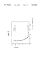
- FIG. 7 is a graph showing the creep (%) according to the added amount of the alloy metals in the Ni--Al anode and Ni--(Al, Cr) anode manufactured by the method according to the present invention, where , , indicates the case of the Ni--Al anode and ⁇ -- ⁇ indicates the case of the Ni-- Al, Cr) anode.
- the manufacturing method according to the present invention is to form an alloy which is composed of a Ni base metal and an additive metal by means of a pack cementation, and the method is performed in a simple manner that only the conditions of atmosphere and temperature are changed while a Ni green sheet is embedded in a pack comprising one or two additive metal powders.
- FIG. 1 is a schematic diagram of the pack cementation procedure for manufacturing the Ni alloy anode according to the present invention.
- the manufacturing method according to the present invention will be described in detail.
- Ni powder, a suitable binder, a plasticizer, etc. are mixed in a proper ratio and suspended in a solvent to form a slurry. Then, a Ni green sheet 1 is formed using a doctor blade.
- Alloy metal powder such as Al or Cr to be added to a Ni base metal is mixed with Al 2 O 3 , an inert filler, and an activator, to form a pack 3.
- an activator NH 4 Cl, NaCl, NaF or NaI may be used.
- NH 4 Cl is preferably used when a pack cementation is performed at a low temperature(near 500° C.)
- NaCl is preferably used at a high temperature (near 800° C.).
- the Ni green sheet 1 formed in the above process is placed in a porous alumina plate 2 and inserted in the middle of the pack 3.
- the pack 3 is then put in an alumina crucible 4.
- the alumina crucible 4 is placed in an electric furnace, and the organic material, such as the binder used for forming the Ni green sheet 1, is burnt and removed by maintaining the pack 3 under an oxygen atmosphere at a temperature of 300° C. to 500° C. for two to five hours.
- pack cementation is performed by elevating the temperature to 500° C. to 800° C. in a H 2 N 2 atmosphere and maintaining the temperature for one to eight hours and thereby forming a MCFC anode which alloys an additive metal such as Al, Cr, etc. to a Ni base metal.
- the alloy metal such as Al, Cr, etc. is reacted with NaCl in the pack 3 to be converted to a gaseous halogen compound and reacted again with Ni to form an intermetallic compound such as Ni--Al, Ni--(Al,Cr), etc.
- the amount of the alloy metal added is related to the temperature and time on the pack cementation process. Under the conditions of the H 2 /N 2 atmosphere and the temperature of 500° C. to 800° C. for one to eight hours, the alloy metal in the Ni alloy may be added in a preferable amount of 2-12% by weight, and in the most preferable amount of 5-12% by weight.
- Ni powder (average particle size: 3 ⁇ m), polyvinyl butyral and dibutyl phthalate were mixed in a proper ratio and suspended in toluene/ethanol to form a slurry. Then, a Ni green sheet was formed using a doctor blade unit. Separately, Al powder (ALCOA, average particle size: 6- 9 ⁇ m) was mixed with Al 2 O 3 (ALCOA, average particle size: 5 ⁇ m) and NaCl (SHINYO, 99.9% pure) to form a pack. Then, the Ni green sheet formed from the above process was placed in a porous alumina plate and inserted in the middle of the pack. The pack was then put in an alumina crucible.
- ALCOA average particle size: 6- 9 ⁇ m
- NaCl SHINYO, 99.9% pure
- the alumina crucible was placed in an electric furnace, and the pack was maintained under an oxygen atmosphere at a temperature of 300° C. to 500° C. for two to five hours.
- pack cementation was performed by elevating the temperature to 500° C. to 800° C. in a 20% H 2 /80% N 2 atmosphere and maintaining the temperature for one to eight hours and thereby forming a Ni--Al alloy to manufacture a MCFC anode.
- Example 2 This example was performed in the same manner as Example 1 except that a MCFC anode was manufactured by mixing a blend of Al and Cr powder with Al 2 O 3 and NaCl to form a pack and thereby form a Ni--(Al,Cr) alloy. According to this Example, Al and Cr were added in the Ni alloy in the amount of 6.2 %.
- FIGS. 2A and 2B are scanning electron microscope (SEM) pictures taken before and after the pack cementation was performed in the Ni--(Al,Cr) anode manufactured by one embodiment according to the present invention, respectively. Comparing the pictures, FIG.2B displays minute particles not shown in FIG. 2A stuck to Ni particles of the electrode.
- the result of analyzing the particles by means of an energy dispersive X-ray analysis (EDXA) is given in the following Table 1, showing the EDXA results for a Ni electrode to which Al and Cr are added.
- FIGS. 3A and 3B are scanning electron microscope (SEM) pictures of the Ni--Al anode manufactured by another embodiment according to the present invention, where FIG.3A shows the surface and FIG.3B shows a section thereof. These also display new small particles to be stuck to Ni particles, which means that Al is added, too.
- FIG. 4 is an X-ray diffraction analysis chart for the Ni--Al anode to which the pack cementation was performed according to an embodiment of the present invention.
- the Al added to the Ni is mainly in the state of an intermetallic compound, Ni 3 Al.
- FIG. 5 is a graph showing the porosity (%) according to the Al content of the Ni--Al anode manufactured according to an embodiment of the present invention. As shown in FIG.5, in the case where 2-12% by weight of Al is included, the porosity is 63 to 74 %, which is suitable range for the use as the MCFC anode.
- reference letter S denotes an electrode sample
- T denotes a thermocouple
- I denotes a dial indicator
- C denotes a compressor
- G denotes a gas outlet.
- FIG.7 is a graph showing the creep (%) according to the added amount of the alloy metals in the Ni--Al anode and Ni--(Al,Cr) anode manufactured by the method according to the present invention, where , , the case of a Ni--Al anode and ⁇ -- ⁇ indicates the case of a Ni--(Al,Cr) anode.
- the creep rate decreased to about 2% and that in the case where Al and Cr were simultaneously added, the creep rate decreased to a level lower than 2%.
- the present invention is performed by one single procedure in which Ni green sheet is embedded in an alumina pack and only the conditions of atmosphere and temperature are changed, wherein a porous MCFC Ni-alloy anode is manufactured by pack cementation, and the creep deformation of the MCFC anode manufactured thereby is very low while its porosity is in an appropriate range(60-80% ), so that the manufacturing process becomes simplified and the cost is greatly reduced.
Landscapes
- Chemical & Material Sciences (AREA)
- Chemical Kinetics & Catalysis (AREA)
- Engineering & Computer Science (AREA)
- Materials Engineering (AREA)
- Electrochemistry (AREA)
- General Chemical & Material Sciences (AREA)
- Mechanical Engineering (AREA)
- Metallurgy (AREA)
- Organic Chemistry (AREA)
- Physics & Mathematics (AREA)
- Thermal Sciences (AREA)
- Manufacturing & Machinery (AREA)
- Ceramic Engineering (AREA)
- Inert Electrodes (AREA)
- Powder Metallurgy (AREA)
Abstract
Description
              TABLE 1
______________________________________
             intensity
                      2-σ error
composition  (cts/sec)
                      (comparative value)
______________________________________
Al           1,043.51 0.0038
Ti             10.10  0.0937
V               5.15  0.1310
Cr             259.27 0.0082
Ni           1,858.20 0.0025
______________________________________
              TABLE 2
______________________________________
Electrode sample       Creep rate(%)
______________________________________
Electrode to which 6% of Al + Cr is added
                       7.5
Electrode to which 6% of Al is added
                       24.0
______________________________________
Claims (2)
Applications Claiming Priority (4)
| Application Number | Priority Date | Filing Date | Title |
|---|---|---|---|
| KR930018664 | 1993-09-16 | ||
| KR93-18664 | 1993-09-16 | ||
| KR93-22736 | 1993-10-29 | ||
| KR1019930022736A KR100195076B1 (en) | 1993-09-16 | 1993-10-29 | Manufacturing method of positive electrode for molten carbonate fuel cell |
Publications (1)
| Publication Number | Publication Date |
|---|---|
| US5415833A true US5415833A (en) | 1995-05-16 |
Family
ID=26629895
Family Applications (1)
| Application Number | Title | Priority Date | Filing Date |
|---|---|---|---|
| US08/220,640 Expired - Lifetime US5415833A (en) | 1993-09-16 | 1994-03-31 | Method for forming molten carbonate fuel cell anodes |
Country Status (5)
| Country | Link |
|---|---|
| US (1) | US5415833A (en) |
| JP (1) | JP2999918B2 (en) |
| KR (1) | KR100195076B1 (en) |
| CN (1) | CN1051406C (en) |
| GB (1) | GB2281916B (en) |
Cited By (9)
| Publication number | Priority date | Publication date | Assignee | Title |
|---|---|---|---|---|
| KR100300757B1 (en) * | 1998-12-31 | 2001-10-29 | 윤영석 | Electrode firing method of molten carbonate fuel cell and its jig |
| US20020122985A1 (en) * | 2001-01-17 | 2002-09-05 | Takaya Sato | Battery active material powder mixture, electrode composition for batteries, secondary cell electrode, secondary cell, carbonaceous material powder mixture for electrical double-layer capacitors, polarizable electrode composition, polarizable electrode, and electrical double-layer capacitor |
| US6585931B1 (en) * | 1995-05-17 | 2003-07-01 | Samsung Electronics Co., Ltd. | Molten carbonate fuel cell anode and method for manufacturing the same |
| US20050031742A1 (en) * | 2003-08-07 | 2005-02-10 | Newkirk Kyle A. | Method for enhancing organoleptic properties of protein for inclusion in consumer food products and products produced thereby |
| US20070022090A1 (en) * | 1998-12-09 | 2007-01-25 | Network Ice Corporation, Inc. | Method and Apparatus for Providing Network and Computer System Security |
| US20080085442A1 (en) * | 2006-10-05 | 2008-04-10 | Abdelkader Hilmi | Anode for use in a fuel cell and method for making same |
| DE102008045286A1 (en) | 2008-08-04 | 2010-02-11 | Mtu Onsite Energy Gmbh | Anode for a molten carbonate fuel cell and process for its preparation |
| US20130032973A1 (en) * | 2011-08-04 | 2013-02-07 | Lucas Thomas M | Method and manufacturing assembly for sintering fuel cell electrodes and impregnating porous electrodes with electrolyte powders by induction heating for mass production |
| EP3899102A4 (en) * | 2018-12-18 | 2022-07-06 | Cellmobility, Inc. | LARGE AREA COPPER NANOMOSSE WITH A HIERARCHICAL STRUCTURE FOR USE AS AN ELECTRODE |
Families Citing this family (1)
| Publication number | Priority date | Publication date | Assignee | Title |
|---|---|---|---|---|
| KR100403133B1 (en) * | 1996-06-19 | 2004-02-25 | 한국전력공사 | METHOD FOR MANUFACTURING ANODE DISTRIBUTION ENHANCED ANODE ELECTRODE BY METAL SALT |
Citations (6)
| Publication number | Priority date | Publication date | Assignee | Title |
|---|---|---|---|---|
| US4315777A (en) * | 1979-08-07 | 1982-02-16 | Scm Corporation | Metal mass adapted for internal oxidation to generate dispersion strengthening |
| US4664883A (en) * | 1986-06-17 | 1987-05-12 | Emhart Industries, Inc. | Method of making electrolytic capacitor anodes |
| US4714586A (en) * | 1986-01-29 | 1987-12-22 | The United States Of America As Represented By The United States Department Of Energy | Method of preparing a dimensionally stable electrode for use in a MCFC |
| US4999155A (en) * | 1989-10-17 | 1991-03-12 | Electric Power Research Institute, Inc. | Method for forming porous oxide dispersion strengthened carbonate fuel cell anodes with improved anode creep resistance |
| US5110541A (en) * | 1990-05-28 | 1992-05-05 | Ishikawajima-Harima Heavy Industries Co., Ltd. | Method of manufacturing electrodes of molten carbonate fuel cell |
| US5312580A (en) * | 1992-05-12 | 1994-05-17 | Erickson Diane S | Methods of manufacturing porous metal alloy fuel cell components |
Family Cites Families (7)
| Publication number | Priority date | Publication date | Assignee | Title |
|---|---|---|---|---|
| GB915090A (en) * | 1958-04-01 | 1963-01-09 | Metallic Surfaces Res Lab Ltd | Improvements in or relating to metallic diffusion processes |
| GB1002820A (en) * | 1962-09-20 | 1965-09-02 | Metallic Surfaces Res Lab Ltd | Improvements in or relating to metallic diffusion |
| NL7008338A (en) * | 1969-06-13 | 1970-12-15 | ||
| US4156042A (en) * | 1975-04-04 | 1979-05-22 | The Secretary Of State For Defence In Her Britannic Majesty's Government Of The United Kingdom Of Great Britain And Northern Ireland | Coating articles having fine bores or narrow cavities in a pack-cementation process |
| DE2633137C2 (en) * | 1976-07-23 | 1983-12-01 | Degussa Ag, 6000 Frankfurt | Boronizing agent for boronizing parts by mass of iron and non-ferrous metals |
| JP2584217B2 (en) * | 1986-11-18 | 1997-02-26 | 株式会社豊田中央研究所 | Surface treatment method |
| DE3742721C1 (en) * | 1987-12-17 | 1988-12-22 | Mtu Muenchen Gmbh | Process for the aluminum diffusion coating of components made of titanium alloys |
-
1993
- 1993-10-29 KR KR1019930022736A patent/KR100195076B1/en not_active Expired - Fee Related
-
1994
- 1994-03-07 GB GB9404330A patent/GB2281916B/en not_active Expired - Fee Related
- 1994-03-31 US US08/220,640 patent/US5415833A/en not_active Expired - Lifetime
- 1994-04-08 CN CN94104486A patent/CN1051406C/en not_active Expired - Fee Related
- 1994-04-15 JP JP6102288A patent/JP2999918B2/en not_active Expired - Fee Related
Patent Citations (6)
| Publication number | Priority date | Publication date | Assignee | Title |
|---|---|---|---|---|
| US4315777A (en) * | 1979-08-07 | 1982-02-16 | Scm Corporation | Metal mass adapted for internal oxidation to generate dispersion strengthening |
| US4714586A (en) * | 1986-01-29 | 1987-12-22 | The United States Of America As Represented By The United States Department Of Energy | Method of preparing a dimensionally stable electrode for use in a MCFC |
| US4664883A (en) * | 1986-06-17 | 1987-05-12 | Emhart Industries, Inc. | Method of making electrolytic capacitor anodes |
| US4999155A (en) * | 1989-10-17 | 1991-03-12 | Electric Power Research Institute, Inc. | Method for forming porous oxide dispersion strengthened carbonate fuel cell anodes with improved anode creep resistance |
| US5110541A (en) * | 1990-05-28 | 1992-05-05 | Ishikawajima-Harima Heavy Industries Co., Ltd. | Method of manufacturing electrodes of molten carbonate fuel cell |
| US5312580A (en) * | 1992-05-12 | 1994-05-17 | Erickson Diane S | Methods of manufacturing porous metal alloy fuel cell components |
Cited By (12)
| Publication number | Priority date | Publication date | Assignee | Title |
|---|---|---|---|---|
| US6585931B1 (en) * | 1995-05-17 | 2003-07-01 | Samsung Electronics Co., Ltd. | Molten carbonate fuel cell anode and method for manufacturing the same |
| US20070022090A1 (en) * | 1998-12-09 | 2007-01-25 | Network Ice Corporation, Inc. | Method and Apparatus for Providing Network and Computer System Security |
| KR100300757B1 (en) * | 1998-12-31 | 2001-10-29 | 윤영석 | Electrode firing method of molten carbonate fuel cell and its jig |
| US20020122985A1 (en) * | 2001-01-17 | 2002-09-05 | Takaya Sato | Battery active material powder mixture, electrode composition for batteries, secondary cell electrode, secondary cell, carbonaceous material powder mixture for electrical double-layer capacitors, polarizable electrode composition, polarizable electrode, and electrical double-layer capacitor |
| US20070172667A1 (en) * | 2001-01-17 | 2007-07-26 | Nisshinbo Industries, Inc. | Battery active material powder mixture, electrode composition for batteries, secondary cell electrode, secondary cell, carbonaceous material powder mixture for electrical double-layer capacitors, polarizable electrode composition, polarizable electrode, and electrical double-layer capacitor |
| US20050031742A1 (en) * | 2003-08-07 | 2005-02-10 | Newkirk Kyle A. | Method for enhancing organoleptic properties of protein for inclusion in consumer food products and products produced thereby |
| US20080085442A1 (en) * | 2006-10-05 | 2008-04-10 | Abdelkader Hilmi | Anode for use in a fuel cell and method for making same |
| US8062779B2 (en) | 2006-10-05 | 2011-11-22 | Fuelcell Energy, Inc. | Anode for use in a fuel cell and method for making same |
| DE102008045286A1 (en) | 2008-08-04 | 2010-02-11 | Mtu Onsite Energy Gmbh | Anode for a molten carbonate fuel cell and process for its preparation |
| US20130032973A1 (en) * | 2011-08-04 | 2013-02-07 | Lucas Thomas M | Method and manufacturing assembly for sintering fuel cell electrodes and impregnating porous electrodes with electrolyte powders by induction heating for mass production |
| US9642192B2 (en) * | 2011-08-04 | 2017-05-02 | Fuelcell Energy, Inc. | Method and manufacturing assembly for sintering fuel cell electrodes and impregnating porous electrodes with electrolyte powders by induction heating for mass production |
| EP3899102A4 (en) * | 2018-12-18 | 2022-07-06 | Cellmobility, Inc. | LARGE AREA COPPER NANOMOSSE WITH A HIERARCHICAL STRUCTURE FOR USE AS AN ELECTRODE |
Also Published As
| Publication number | Publication date |
|---|---|
| GB9404330D0 (en) | 1994-04-20 |
| JP2999918B2 (en) | 2000-01-17 |
| CN1051406C (en) | 2000-04-12 |
| KR100195076B1 (en) | 1999-06-15 |
| JPH0785876A (en) | 1995-03-31 |
| CN1100568A (en) | 1995-03-22 |
| GB2281916A (en) | 1995-03-22 |
| GB2281916B (en) | 1997-05-28 |
Similar Documents
| Publication | Publication Date | Title |
|---|---|---|
| JP2019197742A (en) | Metal-supported solid oxide fuel cell | |
| US5582624A (en) | Process for producing molten-carbonate fuel cells | |
| US8202670B2 (en) | Preconditioning treatment to enhance redox tolerance of solid oxide fuel cells | |
| CA2038408C (en) | Carbonate fuel cell anodes | |
| US5415833A (en) | Method for forming molten carbonate fuel cell anodes | |
| US5589287A (en) | Molten carbonate fuel cell | |
| US5429793A (en) | Scaleable process for producing Ni-Al ODS anode | |
| US20110250521A1 (en) | Method of manufacturing anode for in-situ sintering for molten carbonate fuel cell | |
| JP3228377B2 (en) | Molten carbonate fuel cell cathode and method for suppressing its dissolution | |
| KR0123709B1 (en) | Positive electrode for molten carbonate fuel cell and its manufacturing method | |
| US6585931B1 (en) | Molten carbonate fuel cell anode and method for manufacturing the same | |
| US4891280A (en) | Cathode for molten carbonate fuel cell | |
| US6150048A (en) | Metallic interconnection material for solid oxide fuel cell and method for preparing the same | |
| JP3208935B2 (en) | Method for producing electrode for molten carbonate fuel cell | |
| KR100639425B1 (en) | Anode manufacturing method of molten carbonate fuel cell with high creep resistance | |
| US4939111A (en) | Cathode for molten carbonate fuel cell | |
| CN114583226B (en) | Metal-supported proton conductor solid oxide battery and preparation method thereof | |
| US20230268519A1 (en) | Fuel cell interconnect alloyed with transition metal element and method of making thereof | |
| JPH0520872B2 (en) | ||
| CN114190079B (en) | Solid oxide fuel cell comprising supported anode base promoter | |
| JPH0356631A (en) | Production of sintered plate of porous cu alloy for anode electrode of fused carbonate type fuel cell | |
| CA2244969C (en) | Process for the production of an electrode for a fused carbonate fuel cell, electrode produced according to this process and fused carbonate fuel cell provided with an electrode produced according to this process | |
| JPH07105968A (en) | Molten carbonate fuel cell, its manufacturing method and its operating method | |
| JPS58129767A (en) | Fuel cell electrode | |
| JPH03149755A (en) | Electrodes for molten carbonate fuel cells |
Legal Events
| Date | Code | Title | Description |
|---|---|---|---|
| AS | Assignment |
Owner name: SAMSUNG ELECTRONICS CO., LTD., KOREA, REPUBLIC OF Free format text: ASSIGNMENT OF ASSIGNORS INTEREST;ASSIGNORS:KWEON, HO-JIN;CHUN, HAI-SOO;CHUNG, HA-CHULL;AND OTHERS;REEL/FRAME:006941/0781 Effective date: 19940317 |
|
| STCF | Information on status: patent grant |
Free format text: PATENTED CASE |
|
| FEPP | Fee payment procedure |
Free format text: PAYOR NUMBER ASSIGNED (ORIGINAL EVENT CODE: ASPN); ENTITY STATUS OF PATENT OWNER: LARGE ENTITY |
|
| FPAY | Fee payment |
Year of fee payment: 4 |
|
| FEPP | Fee payment procedure |
Free format text: PAYER NUMBER DE-ASSIGNED (ORIGINAL EVENT CODE: RMPN); ENTITY STATUS OF PATENT OWNER: LARGE ENTITY Free format text: PAYOR NUMBER ASSIGNED (ORIGINAL EVENT CODE: ASPN); ENTITY STATUS OF PATENT OWNER: LARGE ENTITY |
|
| FPAY | Fee payment |
Year of fee payment: 8 |
|
| FPAY | Fee payment |
Year of fee payment: 12 |
|
| AS | Assignment |
Owner name: QIANG TECHNOLOGIES, LLC, DELAWARE Free format text: ASSIGNMENT OF ASSIGNORS INTEREST;ASSIGNOR:SAMSUNG ELECTRONICS CO., LTD.;REEL/FRAME:020654/0287 Effective date: 20080219 |