US5415744A - Removal of contaminant material from a soil site - Google Patents

Removal of contaminant material from a soil site Download PDF

Info

Publication number
US5415744A
US5415744A US08/252,442 US25244294A US5415744A US 5415744 A US5415744 A US 5415744A US 25244294 A US25244294 A US 25244294A US 5415744 A US5415744 A US 5415744A
Authority
US
United States
Prior art keywords
source electrode
sink
electrodes
electrode
soil site
Prior art date
Legal status (The legal status is an assumption and is not a legal conclusion. Google has not performed a legal analysis and makes no representation as to the accuracy of the status listed.)
Expired - Fee Related
Application number
US08/252,442
Inventor
Richard A. Jacobs
Current Assignee (The listed assignees may be inaccurate. Google has not performed a legal analysis and makes no representation or warranty as to the accuracy of the list.)
Massachusetts Institute of Technology
Original Assignee
Massachusetts Institute of Technology
Priority date (The priority date is an assumption and is not a legal conclusion. Google has not performed a legal analysis and makes no representation as to the accuracy of the date listed.)
Filing date
Publication date
Application filed by Massachusetts Institute of Technology filed Critical Massachusetts Institute of Technology
Priority to US08/252,442 priority Critical patent/US5415744A/en
Assigned to MASSACHUSETTS INSTITUTE OF TECHNOLOGY reassignment MASSACHUSETTS INSTITUTE OF TECHNOLOGY ASSIGNMENT OF ASSIGNORS INTEREST (SEE DOCUMENT FOR DETAILS). Assignors: JACOBS, RICHARD A.
Application granted granted Critical
Publication of US5415744A publication Critical patent/US5415744A/en
Anticipated expiration legal-status Critical
Expired - Fee Related legal-status Critical Current

Links

Images

Classifications

    • EFIXED CONSTRUCTIONS
    • E21EARTH DRILLING; MINING
    • E21BEARTH DRILLING, e.g. DEEP DRILLING; OBTAINING OIL, GAS, WATER, SOLUBLE OR MELTABLE MATERIALS OR A SLURRY OF MINERALS FROM WELLS
    • E21B43/00Methods or apparatus for obtaining oil, gas, water, soluble or meltable materials or a slurry of minerals from wells
    • E21B43/16Enhanced recovery methods for obtaining hydrocarbons
    • E21B43/24Enhanced recovery methods for obtaining hydrocarbons using heat, e.g. steam injection
    • E21B43/2401Enhanced recovery methods for obtaining hydrocarbons using heat, e.g. steam injection by means of electricity
    • BPERFORMING OPERATIONS; TRANSPORTING
    • B01PHYSICAL OR CHEMICAL PROCESSES OR APPARATUS IN GENERAL
    • B01DSEPARATION
    • B01D61/00Processes of separation using semi-permeable membranes, e.g. dialysis, osmosis or ultrafiltration; Apparatus, accessories or auxiliary operations specially adapted therefor
    • B01D61/42Electrodialysis; Electro-osmosis ; Electro-ultrafiltration; Membrane capacitive deionization
    • B01D61/56Electro-osmotic dewatering
    • BPERFORMING OPERATIONS; TRANSPORTING
    • B09DISPOSAL OF SOLID WASTE; RECLAMATION OF CONTAMINATED SOIL
    • B09CRECLAMATION OF CONTAMINATED SOIL
    • B09C1/00Reclamation of contaminated soil
    • B09C1/08Reclamation of contaminated soil chemically
    • B09C1/085Reclamation of contaminated soil chemically electrochemically, e.g. by electrokinetics
    • BPERFORMING OPERATIONS; TRANSPORTING
    • B09DISPOSAL OF SOLID WASTE; RECLAMATION OF CONTAMINATED SOIL
    • B09CRECLAMATION OF CONTAMINATED SOIL
    • B09C2101/00In situ
    • CCHEMISTRY; METALLURGY
    • C02TREATMENT OF WATER, WASTE WATER, SEWAGE, OR SLUDGE
    • C02FTREATMENT OF WATER, WASTE WATER, SEWAGE, OR SLUDGE
    • C02F1/00Treatment of water, waste water, or sewage
    • C02F1/46Treatment of water, waste water, or sewage by electrochemical methods
    • C02F1/469Treatment of water, waste water, or sewage by electrochemical methods by electrochemical separation, e.g. by electro-osmosis, electrodialysis, electrophoresis
    • C02F1/4698Treatment of water, waste water, or sewage by electrochemical methods by electrochemical separation, e.g. by electro-osmosis, electrodialysis, electrophoresis electro-osmosis

Landscapes

  • Engineering & Computer Science (AREA)
  • Life Sciences & Earth Sciences (AREA)
  • Chemical & Material Sciences (AREA)
  • Environmental & Geological Engineering (AREA)
  • Water Supply & Treatment (AREA)
  • Geology (AREA)
  • Mining & Mineral Resources (AREA)
  • Chemical Kinetics & Catalysis (AREA)
  • Geochemistry & Mineralogy (AREA)
  • Physics & Mathematics (AREA)
  • General Life Sciences & Earth Sciences (AREA)
  • Soil Sciences (AREA)
  • Health & Medical Sciences (AREA)
  • Urology & Nephrology (AREA)
  • Fluid Mechanics (AREA)
  • Processing Of Solid Wastes (AREA)

Abstract

A method for removing contaminants from soil site regions in which at least one source electrode is positioned in the soil site and is surrounded by a plurality of sink electrodes so that voltage gradients are established between the source electrode and the sink electrodes. A purging liquid is supplied to the source electrode and is permitted to flow therefrom into the soil site. The voltage gradients cause the purging liquid to move by electroosmosis through the soil site toward the sink electrodes to displace the contaminant material therein and to cause a substantial portion of the contaminant to be moved into the sink electrodes from which the contaminant can be removed.

Description

INTRODUCTION
This invention relates generally to the removal of contaminants from hazardous waste sites by electroosmosis techniques using a purging liquid and, more particularly, to the unique placement of electrodes in such a waste site to provide the most effective contaminant removal.
BACKGROUND OF THE INVENTION
A method for removing contaminant material from a soil site has been described in U.S. Pat. No. 5,074,986 issued to R. F. Probstein et al. on Dec. 24, 1991. In the method described in the Probstein patent, one or more source electrodes are positioned at one or more first locations in the soil site and one or more sink or collector electrodes are positioned at one or more second locations therein. Voltage gradients are established among the source and sink electrodes and a purging liquid is externally supplied to the source electrode(s) and flows therefrom into the soil site. The purging liquid thereupon moves by electroosmosis through the soil site from the source electrode(s) thereby displacing the contaminant material so as to cause it to be moved into the sink electrode(s) from which it is in turn removed from the site.
One technique for electrode placement that was considered therein is to use parallel electrode arrays where a plurality of source electrodes and sink electrodes are arranged in alternating rows throughout the soil site. Because of the relatively large numbers of electrodes required and because the contaminant material must be collected from so many sink electrodes, the manifolding thereof is complicated and relatively costly so that such an arrangement, though effective, is believed to be economically inefficient for many practical situations.
Alternatively, it has been suggested that an effective placement pattern of electrodes in a soil site for soil dewatering and consolidation processes would include the providing of a plurality of source electrodes which are positioned so as to surround a single sink electrode (or a small number of closely spaced sink electrodes). Such an electrode configuration pattern might be considered as desirable in a contaminant removal process in order to make the removal process more effective since the number of sink electrodes can be considerably reduced, often to a single one, and placed at only one relatively small region of the site. Accordingly, the need for a large number of removal channels is eliminated and the cost thereof is substantially reduced. The use of such a pattern, which provides an inwardly radial flow from the source electrodes to the sink electrode, is discussed, for example, in connection with soil dewatering and consolidation processes in the text "Fundamentals of Soil Behavior" by James K. Mitchell, John Wiley and Sons, New York, 1993, 2nd Edition, pp. 256-285.
However, analysis of such a pattern for use in a contaminant removal process of the type described in the Probstein et al. patent shows that relatively large areas of the soil site are left uncleaned, severely limiting the contaminant removal efficiency for the overall site. Moreover, there is no control over what flows into the region so that further contaminant may flow therein from outside the site region and/or the soil may dewater to such an extent that flow may cease, either temporarily or permanently, thereby interrupting the removal process. It is desirable, therefore, to provide a different more satisfactory electrode arrangement which produces the most effective removal of contaminant material from an entire soil site.
BRIEF SUMMARY OF THE INVENTION
In accordance with the invention, in order to avoid the disadvantages of the above discussed electrode array patterns when used in a contaminant removal system of the type disclosed in the Probstein et al. patent, an arrangement of electrodes includes the placement of a plurality of sink electrodes in a manner such as to effectively surround a single source electrode or, alternatively, relatively few closely spaced source electrodes, thereby providing an outward radial flow from the source electrode(s) toward the sink electrodes. The geometry of such an electrode pattern generates an effective electric field distribution which produces the outward radial flow from the source electrode(s). It has been found that such an approach provides significantly higher levels of contaminant removal for a given volume of purge liquid used in the system than the suggested use of a sink electrode surrounded by a plurality of source electrodes.
DESCRIPTION OF THE DRAWINGS
The invention can be be understood with the help of the accompanying drawings wherein
FIG. 1 depicts a plan view in diagrammatic form of an exemplary electrode pattern arrangement in a soil site in accordance with the invention;
FIGS. 2 and 3 depict plan views in diagrammatic form of other exemplary electrode pattern arrangements in accordance with the invention.
FIGS. 4-6 depict plan views in diagrammatic form of previously suggested exemplary electrode pattern arrangements;
FIG. 7 depicts a plan view in diagrammatic form of an alternative electrode pattern arrangement in accordance with the invention using a continuously formed sink electrode;
FIG. 8 depicts a view in section of the pattern of FIG. 7 using a cylindrically shaped sink electrode;
FIG. 9 depicts a view in section of the pattern of FIG. 7 using an annular shaped sink electrode;
FIG. 10 depicts a plan view in diagrammatic form of a plurality of electrode pattern arrangements of the type shown in FIG. 1 to form a nested or tiled pattern thereof in a soil site;
FIGS. 11 and 12 depict plan views in diagrammatic form of a plurality of electrode pattern arrangements of the type shown in FIGS. 2 and 3 to form alternative nested or tiled patterns thereof in a soil site.
DESCRIPTION OF THE INVENTION
Since the basic structure and operation of a system in which the novel technique of the invention can be used are clearly shown and discussed in the aforesaid Probstein et al. patent, such description need not be repeated here and the disclosure of such patent is incorporated by reference herein. The figures herein show diagrammatic representations of electrode patterns in accordance with the invention. Such information, together with that provided in the Probstein et al. patent, provides an adequate disclosure of the invention as would be needed by those in the art to understand and practice the invention.
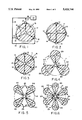
As seen in the exemplary embodiment of FIG. 1, for example, a single source electrode 10 is positioned in a soil site 11 and has a plurality of three sink electrodes 12 which in the particular embodiment shown are substantially symmetrically positioned about the source electrode as shown. An electric field pattern will be developed in the soil site between the source electrode 10 and the sink electrodes 12 due to the supplying of different voltages at the source electrode and at the sink electrodes, which produce voltage gradients between the source electrode and each of the sink electrodes. A purging liquid is supplied to the source electrode in the manner described in the aforesaid Probstein et al. patent. Accordingly, an outward flow of contaminant from the source electrode 10 occurs in the soil site target region 13, a substantial portion of the flow being to the sink electrodes 12, as shown by arrows 14. The contaminant flowing to the sink electrodes can then be removed from the sink electrodes, as discussed below. Portions of contaminant that do not flow to the sink electrodes will flow to and remain in regions of the soil site which are between the sink electrodes 12 outside the target region 13. Accordingly, the soil site is effectively cleaned of contaminant material throughout the target region 13. Although the overall flow field in the target region normally will have a relatively complicated and non-uniform pattern, for simplicity the complete flow field pattern is not depicted in detail here.
If additional sink electrodes are used, as seen in FIGS. 2 and 3, where four and six sink electrodes, respectively, are positioned about a source electrode 10, even more of the soil site will be cleared, as shown by purged target regions 15 and 16, respectively. It is clear that the use of even more sink electrodes would provide for cleaning of even more of the soil site region. A balance between the number of sink electrodes utilized about the source electrode and the costs of providing additional electrodes and accommodating the collection from all of the sink electrodes to achieve the increase in cleaning efficiency that results will normally determine the electrode pattern arrangement used in any particular application.
Such contaminant clearance patterns can be contrasted with those achieved by using patterns previously suggested for use in soil dewatering and consolidation processes, wherein a patterns which use a single sink electrode is surrounded by a plurality of source electrodes. As seen in FIG. 4, a plurality of three source electrodes 20 are symmetrically positioned about a single sink electrode 21 and the area from which the contaminant is removed is limited only to the three regions 22 depicted therein. While the areas of such regions will be increased when using four or six source electrodes 20, as shown by regions 23 and 24 in FIGS. 5 and 6, respectively, relatively large regions of the site in each case will still remain uncleaned, i.e., contaminant removal will not be achieved in such regions, thereby severely limiting the removal efficiency for the target region of the soil site.
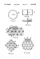
The contaminant being removed from sink electrodes 12 in the exemplary configurations of the invention shown in FIGS. 1-3 can be suitably manifolded as shown specifically in FIG. 1 by a plurality of separate channels 17 connected from each electrode to a single common channel 18, preferably located at the surface of the site so that the contaminant material can be supplied to a suitable effluent collector 19 in a manner as discussed in the aforesaid Probstein et al. patent. Similar manifolding arrangements (for simplicity not shown) can be used in the patterns depicted in FIGS. 2 and 3.
While the voltage gradients between the source electrode and each of the sink electrodes are often the same, in some applications, in order to improve performance it may be desirable to provide different voltage gradients between the source electrode and different ones of the sink electrodes, as well as to provide voltage gradients among the sink electrodes themselves. Moreover, in some applications, it may be desirable to change the voltages supplied to the source and sink electrodes over time so as to provide time varying voltage gradients between the source electrodes and the sink electrodes, as well as between the sink electrodes. The flexibility achievable by being able to use uniform or non-uniform voltage gradients between the source electrodes and the sink electrodes as well as time variant voltage gradients permits the invention to provide the most effective soil site cleaning operations for many different applications.
Further, while the direction of flow in the target region will be generally in an outward direction from the source electrodes, the polarities of the voltages applied to the electrodes, i.e., whether the electrodes act as anodes or cathodes, will depend on the polarity of the charge of the soil in the soil site. Thus, in positively charged soil, for example, the sink electrodes can be anode electrodes and the source electrode is a cathode electrode, the flow taking place outwardly from the cathode source electrode toward the anode sink electrodes, while in negatively charged soil, the sink electrodes are cathodes and the source electrode is an anode, the flow taking place outwardly from the source anode toward the sink cathodes. If the polarity of the charge of the soil changes during a removal operation, the polarities of the voltages supplied to the electrodes can be appropriately changed accordingly to assure that the outward flow is maintained.
Alternatively, rather than using a plurality of separate sink electrodes surrounding the source electrode, a single continuous sink, or collector, electrode 30 can be used, as shown in FIG. 7. The single sink electrode 30 has a closed geometric configuration so as to substantially completely surround the source electrode 31. In the exemplary embodiment, the continuous sink electrode 30 has a substantially circular configuration. Such sink electrode can have a substantially cylindrical shape as shown by electrode 32, the height of which is substantially coextensive with that of a cylindrical source electrode 33, as shown in FIG. 8. Alternatively, it may have an annular shape, as shown in FIG. 9. Any appropriate channel connection (not shown) can be made to the sink electrode to carry the contaminant material to an effluent collector.
For large scale soil sites, a plurality of patterns of the type depicted in FIGS. 1-3 can be used to effectively remove contaminants therein. Thus, as shown in FIG. 10, a first electrode pattern 35 comprises a source electrode 36 surrounded by three sink electrodes 37, a second electrode pattern 38 comprises a source electrode 39 surrounded by three sink electrodes, i.e., two of the sink electrodes 37 and a fourth sink electrode 40, a third electrode pattern 41 comprises a source electrode 42, surrounded by three sink electrodes, i.e., a sink electrode 37, a sink electrode 40, and a further sink electrode 43, and so forth, whereby a plurality of "nested" or "tiled" electrode patterns can be arranged to cover a relatively large soil site area. The outward flows in each pattern are as discussed above in FIG. 1 and generally shown by arrows 44.
Alternative tiled electrode patterns using configurations in which the individual patterns are readily nested together are shown in FIGS. 11 and 12 which depict, respectively, the use of a single source electrode 50 and four sink electrodes 51 in each pattern, and the use of a single source electrode 52 and six sink electrodes 53 in each pattern, to produce the desired overall nested or tiled arrangements.
While in the particular embodiments of the invention discussed above, a single source electrode is used, alternatively, several source electrodes which are closely spaced together at the center of each pattern can be used, the same voltage preferably being supplied to each of the source electrodes in such case. Moreover, while for purposes of explanation the sink electrodes in FIGS. 1-3, for example, are shown as substantially symmetrically positioned about the same source electrode, in some cases, for different soil site shapes or where the properties of the soil site material may not be uniform throughout the site, it may not be desirable to position the sink electrodes symmetrically about the source electrode but rather to place them in an appropriate non-symmetrical pattern to better fit the soil site shape or material variations. Moreover, even when the sink electrodes are symmetrically positioned, they need not form a circular pattern thereof and may assume another geometric shape, e.g., a square, rectangular or other appropriate geometric shape. Other modifications may occur to those in the art within the spirit and scope of the invention. Hence, the invention is not to be construed as limited to the specific embodiments described except as defined by the appended claims.

Claims (19)

What is claimed is:
1. A method of removing a contaminating material from a soil site comprising the steps of
positioning a single source electrode at a first location within said soil site;
positioning a plurality of only sink electrodes at second locations around said source electrode;
establishing voltage gradients between said source electrode and said plurality of sink electrodes;
supplying a non-contaminating purging liquid from a source thereof external to said soil site to said source electrode, said source electrode being arranged to permit said purging liquid to flow from said source electrode into said soil site, the one or more voltage gradients causing said purging liquid to move by electroosmosis through said soil site outwardly from said source electrode toward said sink electrodes and to displace said material so as to cause a substantial portion of the displaced material to be moved from said soil site into said one or more sink electrodes; and
removing said material from said sink electrodes.
2. A method in accordance with claim 1, and further wherein a portion of the displaced material is moved from the soil site to regions outside said soil site.
3. A method in accordance with claim 1, wherein said sink electrodes are substantially symmetrically positioned around said source electrode.
4. A method in accordance with claim 1, wherein at least three sink electrodes are positioned around said source electrode.
5. A method in accordance with claim 1, wherein the voltage gradients between said source electrode and each of said sink electrodes are substantially the same.
6. A method in accordance with claim 1, wherein the voltage gradient between said source electrode and each of said sink electrodes are different and voltage gradients are established among said sink electrodes.
7. A method in accordance with claim 1, wherein the voltage gradients between said source electrodes and each of said sink electrodes vary with time.
8. A method in accordance with claim 1, wherein the polarities of the voltage gradients between said source electrodes and each of said sink electrodes depend on the polarity of the charge of the soil in said soil site.
9. A method in accordance with claim 1, wherein said source electrode comprises a plurality of source electrodes positioned closely together.
10. A method in accordance with claim 1, wherein said removing step comprises
removing soil material from each sink electrode via separate channels; and
combining the removed material from each of said separate channels into a single channel for delivery to a collector.
11. A method of removing contaminating material from a soil site comprising the steps of
positioning a plurality of source electrodes at selected locations within said soil site;
positioning sink electrodes within said soil site at locations such that within a specified distance from each source electrode, each source electrode is surrounded only by a plurality of sink electrodes;
establishing voltage gradients from each said source electrode and its surrounding sink electrodes;
supplying a non-contaminating purging liquid from a source thereof external to said soil site to each of said source electrodes, each said source electrode being arranged to permit said purging liquid to flow from said source electrode into said soil site, the one or more voltage gradients causing said purging liquid to move by electroosmosis through said soil site outwardly from each source electrode toward the sink electrodes surrounding each said source electrode and to displace said material so as to cause the displaced material to be moved from said soil site into said sink electrodes; and
removing said materials from said sink electrodes.
12. A method in accordance with claim 11, wherein at least some of the sink electrodes surrounding each of said source electrodes are commonly used to surround a source electrode and one or more neighboring source electrodes so that a plurality of combinations of a source electrode and associated surrounding sink electrodes are formed in a nested fashion throughout said soil site.
13. A method in accordance with claim 11, wherein each source electrode is surrounded by four electrodes within a specified distance of each source electrode.
14. A method in accordance with claim 11, wherein each source electrode is surrounded by six sink electrodes within a specified distance of each source electrode.
15. A method of recovering a contaminating material from a soil site comprising the steps of
positioning at least one source electrode at a selected location within said soil site;
positioning a continuously formed sink electrode having a selected geometric configuration at a location wherein the continuous sink electrode surrounds said at least one source electrode;
establishing a radially outwardly directed voltage gradient between said at least one source electrode and said surrounding continuously formed sink electrode;
supplying a non-contaminating purging liquid from a source thereof external to said soil site to said at least one source electrode, and at least one source electrode being arranged to permit said purging liquid to flow from said at least one source electrode into said soil site, the one or more voltage gradients causing said purging liquid to move by electroosmosis through said soil site toward said continuously formed sink electrode and to displace said materials so as to cause the displaced material to be moved from said soil site into said sink electrode; and
removing said material from said sink electrode.
16. A method in accordance with claim 15 and further including the steps of forming said continuously formed sink electrode to provide a closed geometric configuration around said at least one source electrode.
17. A method in accordance with claim 16, wherein said continuously formed sink electrode is formed to have a substantially circular configuration.
18. A method in accordance with claim 17, wherein said continuously formed circular sink electrode has an annular configuration.
19. A method in accordance with claim 17, wherein said continuously formed circular sink electrode has a cylindrical configuration.
US08/252,442 1994-06-01 1994-06-01 Removal of contaminant material from a soil site Expired - Fee Related US5415744A (en)

Priority Applications (1)

Application Number Priority Date Filing Date Title
US08/252,442 US5415744A (en) 1994-06-01 1994-06-01 Removal of contaminant material from a soil site

Applications Claiming Priority (1)

Application Number Priority Date Filing Date Title
US08/252,442 US5415744A (en) 1994-06-01 1994-06-01 Removal of contaminant material from a soil site

Publications (1)

Publication Number Publication Date
US5415744A true US5415744A (en) 1995-05-16

Family

ID=22956019

Family Applications (1)

Application Number Title Priority Date Filing Date
US08/252,442 Expired - Fee Related US5415744A (en) 1994-06-01 1994-06-01 Removal of contaminant material from a soil site

Country Status (1)

Country Link
US (1) US5415744A (en)

Cited By (13)

* Cited by examiner, † Cited by third party
Publication number Priority date Publication date Assignee Title
US5584980A (en) * 1994-12-05 1996-12-17 E. I. Du Pont De Nemours And Company Electric field method and apparatus for decontaminating soil
US5944979A (en) * 1996-03-18 1999-08-31 Universite De Sherbrooke Electrokinetic transfer of contaminants from a thin layer of soil to a thin porous medium
US5975799A (en) * 1997-10-06 1999-11-02 The Regents Of The University Of California Electro-osmotic infusion for joule heating soil remediation techniques
GB2344829A (en) * 1998-12-17 2000-06-21 Korea Atomic Energy Res Electrokinetic decontamination of radioactive soil
US6210078B1 (en) * 1999-06-02 2001-04-03 Southern Company Services Methods for the in situ removal of a contaminant from soil
US6228247B1 (en) 1994-12-05 2001-05-08 E. I. Du Pont De Nemours And Company Electric field method and apparatus for decontaminating soil
US6413399B1 (en) * 1999-10-28 2002-07-02 Kai Technologies, Inc. Soil heating with a rotating electromagnetic field
US20090142137A1 (en) * 2007-11-26 2009-06-04 Pioneer Professional Services Group Ltd. Assessment and remediation process for contaminated sites
US8992122B2 (en) 2011-10-12 2015-03-31 Empire Technology Development Llc Electro-remediation
CN110240388A (en) * 2019-06-06 2019-09-17 河南工程学院 Exchange electrode electro-osmosis sludge dewatering system and method based on voltage hierarchical detection
US10500618B2 (en) * 2016-03-31 2019-12-10 North China Electric Power University Apparatus and method for remediating trichloroethylene-polluting soils by integrated rotated migration and PRB
CN111545562A (en) * 2020-05-19 2020-08-18 华东理工大学 Method for repairing organic-polluted low-permeability soil by homogenizing mass transfer electric field-electric-thermal conduction coupling
CN114367533A (en) * 2022-01-18 2022-04-19 陕西省土地工程建设集团有限责任公司 Soil remediation system and method

Citations (21)

* Cited by examiner, † Cited by third party
Publication number Priority date Publication date Assignee Title
US2831804A (en) * 1956-01-30 1958-04-22 Collopy Electro Soil Company Process for the improvement and reclamation of soils
US3417823A (en) * 1966-12-22 1968-12-24 Mobil Oil Corp Well treating process using electroosmosis
US3424662A (en) * 1965-10-15 1969-01-28 Continental Oil Co Use of electro osmosis plus freezing in construction of underground storage tanks
US3782465A (en) * 1971-11-09 1974-01-01 Electro Petroleum Electro-thermal process for promoting oil recovery
US4115233A (en) * 1976-12-27 1978-09-19 Monsanto Company Treatment of aqueous dispersions
US4132625A (en) * 1978-03-16 1979-01-02 Sewage Osmosis Inc. Sewage osmosis system
SU762913A1 (en) * 1978-07-20 1980-09-15 Le Polt I Im M I Kalinina Method of electroosmotical dehydration
SU865225A1 (en) * 1979-07-02 1981-09-23 Всесоюзный научно-исследовательский институт электрификации сельского хозяйства Device for soil electric reclamation
US4305800A (en) * 1980-03-20 1981-12-15 Christenson Lowell B Method of directing water by electro-osmosis to an electrically conductive pile
US4453594A (en) * 1983-04-25 1984-06-12 The United States Of America As Represented By The Secretary Of The Interior Solution mining of coal by electrolysis
US4479857A (en) * 1983-09-01 1984-10-30 Phillips Petroleum Company Method and apparatus for radon control
US4495990A (en) * 1982-09-29 1985-01-29 Electro-Petroleum, Inc. Apparatus for passing electrical current through an underground formation
NL8702005A (en) * 1987-08-27 1989-03-16 Ir Frans Gustaaf Van Der Hoeve Removing heavy metals, esp. cadmium, from contaminated earth - by inserting electrodes and passing current between them to deposit heavy metal at cathode
US4956535A (en) * 1987-06-08 1990-09-11 Battelle Memorial Institute Electrode systems for in situ vitrification
CA2001076A1 (en) * 1989-10-16 1991-04-16 Tomas Kopecek Use of electromagnetic fields of intensities above background for purifying soil and similar contaminated substances
US5074986A (en) * 1989-06-06 1991-12-24 Massachusetts Institute Of Technology Electroosmosis techniques for removing materials from soil
US5098538A (en) * 1989-11-06 1992-03-24 Battelle Memorial Institute Electroacoustic soil decontamination
US5114277A (en) * 1991-02-22 1992-05-19 Battelle Memorial Institute Vitrified underground structures
US5137608A (en) * 1989-11-30 1992-08-11 Board Of Supervisors Of Louisiana State University And Agricultural And Mechanical College Electrochemical decontamination of soils or slurries
WO1993009888A1 (en) * 1991-11-13 1993-05-27 Battelle Memorial Institute Heating to detoxify solid earthen material having contaminants
US5240570A (en) * 1992-01-29 1993-08-31 General Electric Company Surfactant augmented in-situ removal of PCBs from soil by electroosmosis

Patent Citations (21)

* Cited by examiner, † Cited by third party
Publication number Priority date Publication date Assignee Title
US2831804A (en) * 1956-01-30 1958-04-22 Collopy Electro Soil Company Process for the improvement and reclamation of soils
US3424662A (en) * 1965-10-15 1969-01-28 Continental Oil Co Use of electro osmosis plus freezing in construction of underground storage tanks
US3417823A (en) * 1966-12-22 1968-12-24 Mobil Oil Corp Well treating process using electroosmosis
US3782465A (en) * 1971-11-09 1974-01-01 Electro Petroleum Electro-thermal process for promoting oil recovery
US4115233A (en) * 1976-12-27 1978-09-19 Monsanto Company Treatment of aqueous dispersions
US4132625A (en) * 1978-03-16 1979-01-02 Sewage Osmosis Inc. Sewage osmosis system
SU762913A1 (en) * 1978-07-20 1980-09-15 Le Polt I Im M I Kalinina Method of electroosmotical dehydration
SU865225A1 (en) * 1979-07-02 1981-09-23 Всесоюзный научно-исследовательский институт электрификации сельского хозяйства Device for soil electric reclamation
US4305800A (en) * 1980-03-20 1981-12-15 Christenson Lowell B Method of directing water by electro-osmosis to an electrically conductive pile
US4495990A (en) * 1982-09-29 1985-01-29 Electro-Petroleum, Inc. Apparatus for passing electrical current through an underground formation
US4453594A (en) * 1983-04-25 1984-06-12 The United States Of America As Represented By The Secretary Of The Interior Solution mining of coal by electrolysis
US4479857A (en) * 1983-09-01 1984-10-30 Phillips Petroleum Company Method and apparatus for radon control
US4956535A (en) * 1987-06-08 1990-09-11 Battelle Memorial Institute Electrode systems for in situ vitrification
NL8702005A (en) * 1987-08-27 1989-03-16 Ir Frans Gustaaf Van Der Hoeve Removing heavy metals, esp. cadmium, from contaminated earth - by inserting electrodes and passing current between them to deposit heavy metal at cathode
US5074986A (en) * 1989-06-06 1991-12-24 Massachusetts Institute Of Technology Electroosmosis techniques for removing materials from soil
CA2001076A1 (en) * 1989-10-16 1991-04-16 Tomas Kopecek Use of electromagnetic fields of intensities above background for purifying soil and similar contaminated substances
US5098538A (en) * 1989-11-06 1992-03-24 Battelle Memorial Institute Electroacoustic soil decontamination
US5137608A (en) * 1989-11-30 1992-08-11 Board Of Supervisors Of Louisiana State University And Agricultural And Mechanical College Electrochemical decontamination of soils or slurries
US5114277A (en) * 1991-02-22 1992-05-19 Battelle Memorial Institute Vitrified underground structures
WO1993009888A1 (en) * 1991-11-13 1993-05-27 Battelle Memorial Institute Heating to detoxify solid earthen material having contaminants
US5240570A (en) * 1992-01-29 1993-08-31 General Electric Company Surfactant augmented in-situ removal of PCBs from soil by electroosmosis

Non-Patent Citations (7)

* Cited by examiner, † Cited by third party
Title
"Determination of pH Gradients in the Electrochemical Processing of Kaolinite", Greg A. Putnam, Dec., 1988.
"Fundamentals of Soil Behavior", James K. Mitchell, Second Edition, University of California, Berkeley. no date.
"Potential Uses of Electro-Kinetics for Hazardous Waste Site Remediation", James K. Mitchell, Aug. 4-5, 1986.
Determination of pH Gradients in the Electrochemical Processing of Kaolinite , Greg A. Putnam, Dec., 1988. *
English Abstract of 007847339. NL patent 188,415B Jan. 1992. *
Fundamentals of Soil Behavior , James K. Mitchell, Second Edition, University of California, Berkeley. no date. *
Potential Uses of Electro Kinetics for Hazardous Waste Site Remediation , James K. Mitchell, Aug. 4 5, 1986. *

Cited By (16)

* Cited by examiner, † Cited by third party
Publication number Priority date Publication date Assignee Title
US5584980A (en) * 1994-12-05 1996-12-17 E. I. Du Pont De Nemours And Company Electric field method and apparatus for decontaminating soil
US6228247B1 (en) 1994-12-05 2001-05-08 E. I. Du Pont De Nemours And Company Electric field method and apparatus for decontaminating soil
US5944979A (en) * 1996-03-18 1999-08-31 Universite De Sherbrooke Electrokinetic transfer of contaminants from a thin layer of soil to a thin porous medium
US5975799A (en) * 1997-10-06 1999-11-02 The Regents Of The University Of California Electro-osmotic infusion for joule heating soil remediation techniques
GB2344829A (en) * 1998-12-17 2000-06-21 Korea Atomic Energy Res Electrokinetic decontamination of radioactive soil
US6214189B1 (en) * 1998-12-17 2001-04-10 Korea Atomic Energy Research Institute Method for electro-kinetically decontaminating soil contained in a radioactive waste drum, and apparatus therefor
GB2344829B (en) * 1998-12-17 2001-07-18 Korea Atomic Energy Res Method for electro-kinetically decontaminating soil contained in a radioactive waste drum, and apparatus therefor
US6210078B1 (en) * 1999-06-02 2001-04-03 Southern Company Services Methods for the in situ removal of a contaminant from soil
US6413399B1 (en) * 1999-10-28 2002-07-02 Kai Technologies, Inc. Soil heating with a rotating electromagnetic field
US20090142137A1 (en) * 2007-11-26 2009-06-04 Pioneer Professional Services Group Ltd. Assessment and remediation process for contaminated sites
US8992122B2 (en) 2011-10-12 2015-03-31 Empire Technology Development Llc Electro-remediation
US10500618B2 (en) * 2016-03-31 2019-12-10 North China Electric Power University Apparatus and method for remediating trichloroethylene-polluting soils by integrated rotated migration and PRB
CN110240388A (en) * 2019-06-06 2019-09-17 河南工程学院 Exchange electrode electro-osmosis sludge dewatering system and method based on voltage hierarchical detection
CN110240388B (en) * 2019-06-06 2023-09-12 河南工程学院 Exchange electrode electroosmosis sludge dewatering system and method based on voltage grading detection
CN111545562A (en) * 2020-05-19 2020-08-18 华东理工大学 Method for repairing organic-polluted low-permeability soil by homogenizing mass transfer electric field-electric-thermal conduction coupling
CN114367533A (en) * 2022-01-18 2022-04-19 陕西省土地工程建设集团有限责任公司 Soil remediation system and method

Similar Documents

Publication Publication Date Title
US5415744A (en) Removal of contaminant material from a soil site
US5733360A (en) Corona discharge reactor and method of chemically activating constituents thereby
US5603752A (en) Electrostatic precipitator
US7861667B2 (en) Multi-part electrode for a semiconductor processing plasma reactor and method of replacing a portion of a multi-part electrode
US5900064A (en) Plasma process chamber
EP0993024B1 (en) Electrostatic chuck
US4126530A (en) Method and apparatus for sputter cleaning and bias sputtering
US20060151114A1 (en) Plasma processing system and baffle assembly for use in plasma processing system
NO982680D0 (en) Screen for vibrating separator
US20040066601A1 (en) Electrode configuration for retaining cooling gas on electrostatic wafer clamp
DE202010014805U1 (en) Hot edge ring with inclined upper surface
DE202011102440U1 (en) C-shaped enclosure ring for a plasma processing chamber
DE202010004773U1 (en) Sealing element with postioning feature for a clamped monolithic gas distribution electrode
EP0413726B1 (en) Electrical apparatus
JP5313893B2 (en) Ion deposition equipment
EP0066850A2 (en) Semiconductor switching device
JPH09501794A (en) Treatment of particulate matter by electric discharge
EP0221527A2 (en) Hydraulic filter system for excavation equipment
US4431434A (en) Electrostatic precipitator using a temperature controlled electrode collector
US5332484A (en) Apparatus and process for the large scale separation and retrieval of proteins from cellular extracts
EP0271298A2 (en) Improved apparatus for electrolytic reaction
US7682827B2 (en) Microelectronic positioning for bioparticles
KR960039090A (en) Electron gun and its driving circuit
KR200141803Y1 (en) Magnetron type sputtering apparatus
JPS6222587A (en) Device for cell fusion

Legal Events

Date Code Title Description
AS Assignment

Owner name: MASSACHUSETTS INSTITUTE OF TECHNOLOGY, MASSACHUSET

Free format text: ASSIGNMENT OF ASSIGNORS INTEREST;ASSIGNOR:JACOBS, RICHARD A.;REEL/FRAME:007024/0316

Effective date: 19940531

FEPP Fee payment procedure

Free format text: PAYOR NUMBER ASSIGNED (ORIGINAL EVENT CODE: ASPN); ENTITY STATUS OF PATENT OWNER: LARGE ENTITY

FEPP Fee payment procedure

Free format text: PAT HLDR NO LONGER CLAIMS SMALL ENT STAT AS NONPROFIT ORG (ORIGINAL EVENT CODE: LSM3); ENTITY STATUS OF PATENT OWNER: LARGE ENTITY

FPAY Fee payment

Year of fee payment: 4

REMI Maintenance fee reminder mailed
LAPS Lapse for failure to pay maintenance fees
STCH Information on status: patent discontinuation

Free format text: PATENT EXPIRED DUE TO NONPAYMENT OF MAINTENANCE FEES UNDER 37 CFR 1.362

FP Lapsed due to failure to pay maintenance fee

Effective date: 20030516