US5404363A - Two-fail-operational fault-tolerant multiple clock system - Google Patents
Two-fail-operational fault-tolerant multiple clock system Download PDFInfo
- Publication number
- US5404363A US5404363A US07/800,904 US80090491A US5404363A US 5404363 A US5404363 A US 5404363A US 80090491 A US80090491 A US 80090491A US 5404363 A US5404363 A US 5404363A
- Authority
- US
- United States
- Prior art keywords
- clock
- fault
- modules
- receiver
- module
- Prior art date
- Legal status (The legal status is an assumption and is not a legal conclusion. Google has not performed a legal analysis and makes no representation as to the accuracy of the status listed.)
- Expired - Lifetime
Links
Images


Classifications
-
- G—PHYSICS
- G06—COMPUTING; CALCULATING OR COUNTING
- G06F—ELECTRIC DIGITAL DATA PROCESSING
- G06F11/00—Error detection; Error correction; Monitoring
- G06F11/07—Responding to the occurrence of a fault, e.g. fault tolerance
- G06F11/16—Error detection or correction of the data by redundancy in hardware
- G06F11/1604—Error detection or correction of the data by redundancy in hardware where the fault affects the clock signals of a processing unit and the redundancy is at or within the level of clock signal generation hardware
-
- G—PHYSICS
- G06—COMPUTING; CALCULATING OR COUNTING
- G06F—ELECTRIC DIGITAL DATA PROCESSING
- G06F1/00—Details not covered by groups G06F3/00 - G06F13/00 and G06F21/00
- G06F1/04—Generating or distributing clock signals or signals derived directly therefrom
- G06F1/12—Synchronisation of different clock signals provided by a plurality of clock generators
-
- G—PHYSICS
- G06—COMPUTING; CALCULATING OR COUNTING
- G06F—ELECTRIC DIGITAL DATA PROCESSING
- G06F11/00—Error detection; Error correction; Monitoring
- G06F11/07—Responding to the occurrence of a fault, e.g. fault tolerance
- G06F11/16—Error detection or correction of the data by redundancy in hardware
- G06F11/18—Error detection or correction of the data by redundancy in hardware using passive fault-masking of the redundant circuits
- G06F11/187—Voting techniques
-
- G—PHYSICS
- G06—COMPUTING; CALCULATING OR COUNTING
- G06F—ELECTRIC DIGITAL DATA PROCESSING
- G06F11/00—Error detection; Error correction; Monitoring
- G06F11/07—Responding to the occurrence of a fault, e.g. fault tolerance
- G06F11/16—Error detection or correction of the data by redundancy in hardware
- G06F11/1675—Temporal synchronisation or re-synchronisation of redundant processing components
- G06F11/1679—Temporal synchronisation or re-synchronisation of redundant processing components at clock signal level
-
- G—PHYSICS
- G06—COMPUTING; CALCULATING OR COUNTING
- G06F—ELECTRIC DIGITAL DATA PROCESSING
- G06F11/00—Error detection; Error correction; Monitoring
- G06F11/07—Responding to the occurrence of a fault, e.g. fault tolerance
- G06F11/16—Error detection or correction of the data by redundancy in hardware
- G06F11/18—Error detection or correction of the data by redundancy in hardware using passive fault-masking of the redundant circuits
- G06F11/183—Error detection or correction of the data by redundancy in hardware using passive fault-masking of the redundant circuits by voting, the voting not being performed by the redundant components
-
- G—PHYSICS
- G06—COMPUTING; CALCULATING OR COUNTING
- G06F—ELECTRIC DIGITAL DATA PROCESSING
- G06F2201/00—Indexing scheme relating to error detection, to error correction, and to monitoring
- G06F2201/88—Monitoring involving counting
Definitions
- the invention pertains to clocks for digital circuits. More particularly, the invention pertains to clocks having fault tolerance.
- the present invention is a fault tolerant clock having four identical interconnected clock modules.
- This so-called quad clock achieves one fail operability with 100% coverage and two fail operability with virtually 100% coverage.
- the exceptions to the latter coverage include only double failures which occur simultaneously, occur in two separate clock modules, and recognizable as a fault to the unfaulty modules, and are malicious, that is, both faulty modules work to deceive the unfaulty modules. It is the latter double failures which can cause a loss of operation.
- the fault tolerant clock also provides partial coverage for three, four, or more faults, that is, numerous communication lines between the modules may fail.
- the invention provides fault tolerant simultaneous startup. After power-up, the quad clock appears to the outside world, that is, the rest of the electronics supported by the clock, to start simultaneously. This is accomplished through the passing and voting of (ready) flags between modules. The first clock edge transmitted from the separate modules to the outside world occurs simultaneously.
- the simultaneous startup is fault tolerant. Faults on the ready lines are masked, and the most likely faults (e.g., failure to signal ready within a reasonable amount of time) are detected and reported. In a worst situation, multiple failures in the startup circuitry can result in the clock not starting.
- the present invention incorporates fault tolerant operational diagnostics. It includes latent fault detection, wherein "latent” refers to a fault which does not affect the appropriate behavior of the clock as seen by the outside world.
- latent fault detection occurs independently on all four clock modules.
- a fault flag is set when a given module perceives a signal from another module to be faulty.
- Operational status of the clock depends on the fault flags.
- Significant operational status categories are "no faults,” "two-fail-operability,” “one-fail-operability,” “operational,” and “not operational”. Such category information is needed for maintenance scheduling.
- Each of the four modules transmits its clock signal to each of the other modules, which involves twelve point-to-point connections. An additional twelve point-to-point connections are needed to accomplish the fault tolerant simultaneous start-up. An additional twelve point-to-point connections are needed to communicate fault flag information. If each module also sends its flags to itself through interconnections, then there are a total of sixteen interconnection lines or point-to-point connections for flag communication. The latter connections enable the modules to be truly identical with one another.
- the modules incorporate shift registers which are used to store short time histories of received signals and voted clock outputs, permitting all forms of faults to be detected with minimal added combinational logic. Metastability resolution is automatically accomplished by the first stage of the shift register. Standard loadable counters generate the clock signal having an easily selectable clock duty cycle. The entire clock module circuitry fits easily onto a small integrated circuit or programmable circuit of current technology.
- the invention clock design is maximally efficient fulfilling the requirements of two-fail operability/fail-safe operation with fault-tolerant simultaneous start-up and two-fail operability operational status reporting.
- the invention also has a two frequency options that is, it can output one frequency and a multiple of it, containing within them the synchronization and fault-detection loops. Both lower and higher frequency signals are fault tolerant.
- FIGS. 1a-b show the interconnection of four clock modules of the invention and a block diagram of a clock module, respectively.
- FIG. 2 is a detailed block diagram of part of a clock module.
- FIG. 3 shows the four clock modules and their connection to an optional and separate fault containment region receiver.
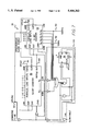
- FIG. 4 is a block diagram of the system incorporating the clock modules, microprocessors and nonvolatile memories.
- FIG. 5 is a schematic of the clock enable circuit of the clock module.
- FIG. 6 is an after power-up initial timing sequence diagram.
- FIG. 7 is a schematic diagram of the clock generator circuit of the clock module.
- FIG. 8 is a schematic diagram of the clock receiver circuit of the clock module.
- FIG. 9 is a schematic of the input clock manager circuit of the clock receiver circuit.
- FIG. 10 is a schematic of the collector circuit of the clock receiver circuit.
- FIG. 11 is a schematic of the reference clock manager circuit of the clock receiver circuit.
- FIG. 12 is a diagram of the fault tolerant reset interconnection topology of a two-failure-operable configuration of the clock system.
- FIG. 13 is a diagram of the topology of a one-failure-operable configuration.
- FIG. 14 is a topology diagram of an operable configuration.
- FIG. 15 shows a timing diagram of the synthesis of the voted clock.
- FIG. 16a is a topology diagram of a transient configuration.
- FIG. 16b is a topology diagram of a stable configuration.
- FIGS. 17a-f are topology diagrams having mono-directional links.
- FIG. 18a is a diagram having a mono-directional link.
- FIG. 18b is a diagram having no mono-directional links.
- FIGS. 19a-c reveal three equivalent network topologies.
- FIGS. 20(a-j) show topology diagrams of ten bi-directional clock configurations and their stability.
- FIG. 21 is a topology diagram of a broken pair configuration.
- FIG. 22 is a functional block diagram of the fault flag communication system.
- FIG. 23 is a fault flag communication timing diagram.
- FIGS. 24a-b are block and timing diagrams of the fault flag communication clock phase.
- FIG. 25 is a diagram of a fault flag communication transmitter.
- FIG. 26a shows set of fault flag communication flag receivers.
- FIG. 26b is a more detailed diagram of a fault flag communication flag receiver.
- FIG. 27 shows a schematic of the fault flag communication line fail detection system.
- FIGS. 28a-b are diagrams of the fault flag permanent latch circuit and latch circuit detail for one bit, respectively.
- FIG. 29 is a table listing of cards and their respective correspondence between the absolute and relative numbers.
- FIG. 30 is a table of the fault flag ordering common to all clocks.
- FIGS. 31a-f are schematics of the combinational logic for operational determinations of the clock and reset systems.
- the present invention is a digital clock circuit designed to tolerate all non-simultaneous double failures.
- the circuit delivers four fault-tolerant 100 hertz clocks synchronized to within 200 nanoseconds of one another with a maximum frequency error of 140 parts per million, four fault-tolerant 1600 hertz clocks synchronized to within 1200 nanoseconds of one another with a maximum frequency error of 140 parts per million, and 32 fault flags to be used to monitor the condition of the circuit and facilitate maintenance diagnostics.
- FIG. 1a reveals clock 10 having four modules 11, 12, 13 and 14 and the interconnections among these modules.
- FIG. 1b is a block diagram of a module 11, 12, 13 or 14. Each module contains reset means 16, clock unit 115 having clock receiver 20 and clock generator 18, and operational diagnostics 17.
- FIG. 2 reveals partial module 15 of each module 11, 12, 13 or 14. Each module also contains a fault flag communication circuit 17 as shown in FIG. 22.
- Four major parts of a module are reset means or fault tolerant reset or clock enable circuit 16 which provides an initial, synchronized enable to all the other clock modules; clock generator circuit 18 which generates the 100 hertz and 1600 hertz outputs; clock receiver circuit 20 which monitors the other three clock modules with input clocks from other modules and provides synchronization commands to clock generator 18; and an operational diagnostic means 17.
- clock receiver 20 outputs fault-tolerant clock and maintenance flags F I , F J , F K , F L .
- FIG. 3 reveals an optional layout 140 having the clock modules 11, 12, 13 and 14 outputting four fault-tolerant clocks, respectively, to a clock receiver circuit 22.
- Clock receiver 22 is similar to receiver 20 in the clock module, except for having a minor combinational logic 64 change, wherein gate 138 is removed for constructing receiver 22.
- Receiver 22 outputs one external fault-tolerant clock signal in optional configuration 140.
- FIG. 4 is an elaboration of FIG. 1 showing the four clock modules indicating their interconnections and external connections with greater detail and interconnection with memories 120 and processors 24 for application to an external system using the clock signals.
- the fault tolerant clock circuit is designed to eliminate all potential faults due to metastable states. Setup and hold times are satisfied for the various digital components within the circuit. Shift registers are utilized to record the recent history of the clock thereby permitting fault-detection and signal synchronization.
- the synchronization requirements are less than 1000 nanosecond skew error between any pair of clock modules' 100 hertz signals, "tight synchronization" between any pair of clock modules' 1600 hertz signals, and less than 200 parts per million frequency error, for one particular application, namely the Air Data Inertial Reference Unit (ADIRU).
- ADIRU Air Data Inertial Reference Unit
- Each clock generator circuit 18 outputs the module's 100 hertz and 1600 hertz synchronous clocks.
- the 100 hertz signals are confined to the fault tolerant clock circuit itself.
- the 1600 hertz signals are delivered to HEXAD units.
- each clock receiver circuit 20 outputs the module's 100 hertz reference clock.
- the reference clocks are delivered to microprocessors 24.
- a HEXAD unit is a six sensor unit wherein the sensors are gyroscopes and/or accelerometers, such that two of the six sensors can fail and the unit remains adequately functional.
- Clock generator 18 has a loadable counter 56 with a load valve selected to control frequency and duty cycle.
- the two stage counter 56, 58 provides 1600 Hz and 100 Hz synchronized clocks. New features include synchronization on the rising and falling edges of the 100 Hz clock and a 50 percent duty cycle on the 1600 Hz and 100 Hz clock outputs. Also, in clock generator 18 is slow fault detection combinational logic 116.
- T S the synchronization period (elapsed nominal time between synchronized edges)
- T HFCLK the period of the high frequency crystal oscillator.
- the formulas indicate that the skew between the outputs of receivers 20 is less than the skew between of the outputs of generators 18. Because receivers 20 drive microprocessors 24, the skew between the receivers' 100 hertz signals should be used to judge clock performance. However, the value of the skew between the generators' 1600 hertz outputs is critical since it is used to test for circuit faults. By including a slightly modified clock receiver circuit 22 on each HEXAD, the skew between the 1600 hertz signals delivered to the HEXAD may be reduced from the skew of equation 1 to that of equation 2 above. An oscillator with 100 parts per million accuracy is utilized for clock generator circuit 18. Equations 1, 2 and 3 above, show that the smaller T HFCLK results in better clock performance.
- T HFCLK 100 nanoseconds
- T S 5 milliseconds
- T S 10 milliseconds
- the accuracy of the frequency is related to the accuracy of the crystal oscillator.
- Reset means or clock enable circuit 16 of FIG. 5 provides an initial, synchronized enable signal to all clock modules, ensuring that the four modules are synchronized to one another when the clock is started, continuously detects, latches and reports latent faults within clock enable circuit 16 itself, and provides metastability resolution.
- Circuit or fault tolerant reset 16 has a 2/4 voter mechanism to provide a two-fail-operational initialization, fault detection logic that detects a hardware failure in reset circuit 16 and latches fault flags, and a master-slave flip-flop combination that provides metastability resolution at circuit initialization.
- the reset means or clock enable circuit 16 consists of combinational logic 106, fault detection reset 108 and reset latch 110.
- Clock enable circuit 16 meets multiple timing requirements at power-up which include that after initial power-up, the clock should not operate until all microprocessors 24 that it drives have been fully initialized, and that all clock modules be synchronized initially.
- Each of clock modules 11, 12, 13 and 14 utilizes an internal clock enable signal 28 which is asserted after microprocessor 24 initialization.
- Signal 28 is asserted well after T B (wherein a minimal intervening period of time is T B -T A ), to ensure that clock modules 11, 12, 13 and 14 have been released from internal clock reset 26. Due to random factors, the four internal clock enable signals 28 are asserted between times T C and T D .
- Clock enable circuit 16 is designed to mask faults within its circuitry. Faults are masked by the 2/4 voter which asserts a verified clock enable signal 30 from combinational logic 106 upon receipt of second clock enable signal. Thus, if one of clock modules 11, 12, 13 or 14 receives its internal clock enable signal 29 (the power up ready signal) grossly early, the fault does not propagate into any of the modules' verified clock enable signals 30. Likewise, if two of clock modules 11, 12, 13 and 14, never assert their internal clock enables 29, all four clocks can still generate their verified clock enables 30.
- Latent faults within enable circuit 16 are detected and reported by sixteen fault flags indicated by outputs 31, 32, 33 and 34 of shift registers 36. These 16 fault flags are included to merely facilitate maintenance; they do not affect the operation of the clock. Each module has four fault flags 31, 32, 33 and 34, corresponding to clock enable signals 37, 38 and 39 from external clocks and signal 29 from the internal clock. A fault flag is asserted if verified clock signal 40 from receiver 20 is asserted before corresponding clock enable signal 29, 37, 38 or 39. All detected faults are latched to prevent transient fault-reporting.
- Clock enable circuit 16 is not too quick to judge an internal enable signal 29 as the circuit is inherently asynchronous. Time is allowed to elapse before concluding that internal clock enable signal 29 is faulty.
- Fault signal 34 which corresponds to internal clock enable signal 29, is disabled initially by delaying verified clock signal 40 through an N-bit digital counter 42. For a sufficient delay by counter 42, the minimum number of bits N is given by the following equation:
- T C minimum time for assertion of internal clock enable
- T D maximum time for assertion of internal clock enable
- T HFCLK period of the high frequency oscillator signal HFCLK.
- a clock module 11, 12, 13 or 14 receives at least two or more clock enable signals 29, 37, 38 or 39, then verified clock enable signal 30 is asserted.
- Verified clock enable signal 30 is latched and synchronized to a local HFCLK signal 44 by two D flip-flops 46.
- Internal synchronous clock enable signal 29 is asserted on the following edge of HFCLK signal 44. Since all synchronous devices within a clock module 11, 12, 13 or 14, are positive-edge triggered, metastability is resolved.
- Flip-flops 46 and counter 42 have an internal clock reset 112 which is an "early" power up reset.
- FIG. 6 reveals the clock enable circuit 16 sequence for initial timing after power-up.
- microprocessor 24 is initialized at least ⁇ period of time prior to the assertion of the respective internal clock reset.
- the respective microprocessor 24 initializations may be completed at various times within an ⁇ period of time.
- the internal clock reset may be asserted.
- the internal clock enable is asserted ⁇ time after the internal clock enable is asserted. ⁇ time is greater than ⁇ time.
- clock generator circuit 18 The purpose of clock generator circuit 18 is to follow synchronization command signals 48 and 50 that it receives from clock receiver circuit 20. In absence of command signals 48 and 50, generator circuit 18 acts as a freely running oscillator.
- FIG. 7 reveals the details of clock generator circuit 18.
- Outputs of generator circuit 18 include a fault tolerant 100 hertz signal which is tightly synchronized to the 100 hertz generator outputs 52 of the other three clock modules, and a fault tolerant 1600 hertz signal 54 which is tightly synchronized to the 1600 hertz generator outputs 54 of the other three clock modules.
- a need for dual 100 hertz and 1600 hertz clock signals, each having a 50% duty cycle, is provided by a divide-by-N stage which is implemented with a tandem counter design.
- a second counter 58 functions as a divide-by-32 stage, providing both 100 hertz and 1600 hertz signals.
- the period of the least significant bit of second counter 58 is one-sixteenth the value of the period of the most significant bit. Although the most significant bit of first counter 56 does not have a fifty percent duty cycle, the five bits of second counter 58 essentially do.
- First counter 56 supplies second counter 58 with a 3200 hertz signal. The 3200 hertz is obtained by dividing the 10 megahertz crystal oscillator HFCLK output 44 by 3125.
- First counter 56 is wired as a divide-by-3125 stage.
- clock receiver circuit 20 When clock receiver circuit 20 obtains a positive reference edge, it asserts UPSYNC signal 50 for one cycle of the high frequency crystal oscillator (HFCLK) signal 44.
- HFCLK high frequency crystal oscillator
- a one or zero is loaded for a 100 Hz clock value when it is synchronized depending whether it is on the rising (up) edge or falling (down) edge, respectfully, to set the clock for the next one-half period.
- First counter 56 is loaded to 001111001011 2 (4096 10 -3125 10 ), while second counter 58 has its most significant bits set to logic one.
- first counter 56 provides a nominal 3200 hertz signal 60 to second counter 58.
- clock receiver circuit 20 If clock receiver circuit 20 obtains a negative reference edge within the next 5 milliseconds, then it will assert DOWNSYNC signal 48 for one cycle of HFCLK signal 44. First counter 56 is then loaded to 0011110011 2 ; second counter 58 has all of its bits set to logic 0. If clock receiver 20 fails to obtain a negative reference edge within the next 5 milliseconds, the second stage of the counter will simply "roll over,” independent of the reference signal; the value of all its bits will be set to logic 0.
- FIG. 8 is a schematic of clock receiver circuit 20.
- Clock receiver circuit 20 detects faults within the fault tolerant clock circuit, reports detected faults to an external system (i.e., a non-volatile memory), uses the knowledge of circuit faults to extract a properly defined reference signal, and provides synchronization command signals 48 and 50 to generator circuit 18. Synchronization command signals 48 and 50 are computed in accordance with a reference signal.
- a slightly modified version of clock receiver circuit 20 is located on each HEXAD unit. Receiver 20 reduces skew between the 1600 hertz synchronous clocks.
- Clock receiver 20 has a new five shift register architecture for saving recent history of received clocks and verified clocks.
- Input clock manager 62 has new combinational logic to generate fault flags, fault flag latch means and a non-volatile memory interface.
- Collector combinational logic 64 votes input clocks based on fault flags.
- a new reference clock manager 66 has combinational logic for producing sync signals 48 and 50, and combinational logic for producing check signals 82 and 88.
- Clock receiver circuit 20 has three major subcircuits.
- a collector 64 performs a median voter algorithm. Reference clock manager 66 removes glitches from candidate reference clock 68 of collector 64. Manager 66 also assists with fault detection and delivers synchronization command signals 48 and 50 to clock generator circuit 18.
- Input clock manager 62 synchronizes the incoming external clock modules' 100 hertz clocks to the local high frequency time base HFCLK 44.
- Input clock manager 62 also detects and reports faults on each of the incoming 100 hertz signals. Even though the internal 100 hertz signal is already synchronized, fault detection and notification is performed on that signal.
- FIG. 9 is a schematic of input clock manager 66. Input synchronization is provided by shift register 68. The first output bit of shift register 68 is synchronized input signal 70 which is sent to collector 64 to be included in
- fault detection and notification circuitry One possible problem is detection of a grossly early edge. For instance, consider the currents of a level transition on one of the clock signals present at the input to input clock manager 62. After (n-1) cycles of HFCLK 44 elapse, signal early check 72 is asserted for one period of HFCLK 44. Simultaneously, output 74 of the (n-1)th bit of shift register 68 is compared with asynchronous reference clock 76 from reference clock manager 66. If the two signals 74 and 76 disagree or differ, then early fault signal 78 is asserted. Early fault signal 78 is based on the fact that no individual clock signal should precede reference clock 76 by too great amount of time.
- n The amount of time that elapses between receiving a clock edge and checking whether that clock edge is early depends on the value of n, that is, the number of bits in the input clock manager 62. Since an early clock edge could belong to a clock module 11, 12, 13 or 14, having a crystal oscillator running slightly fast, the value of n should be chosen large enough to tolerate an acceptable skew due to fluctuations in the oscillator's frequency. Recalling a formula above for tolerable skew between clock generator signals, n should have the value as noted in the following formula.
- T S the synchronization period (elapsed nominal time between synchronized edges)
- T HFCLK the period of the high frequency crystal oscillator.
- clock J of module 12 it is possible for clock J of module 12 to detect the synchronous clock transition of clock I of module 11 almost immediately. However, clock I must wait one full cycle of HFCLK 44 to observe its own clock transition. To avoid this delay, input clock manager 62 corresponding to the internal clock signal may have one less bit in its shift register 68.
- Input clock manager 62 has circuitry for detection of the grossly late edge of an individual clock relative to the reference clock. In other words, a level transition on an input to clock module 11, 12, 13 or 14, is considered grossly late if an unacceptable amount of time elapses between the level of transition on the input and the corresponding level transition on the reference signal of that module. None of a module's input clocks should lag its reference clock by too great amount of time.
- a clock module detects a reference edge, that means at least two of the other clock modules have recently transitioned.
- the clock module that detects the reference edge then transitions its own synchronous signal. By this time, at least three of the four modules have transitioned.
- the fourth clock will then transition after a voter delay consisting of at most two cycles of its own HFCLK 44. Within one cycle of its own HFCLK 44, the other three modules will see the transition of the fourth module.
- the total time elapsed is 3 cycles of HFCLK 44.
- late check signal 82 When a reference clock edge is detected, late check signal 82 is provided by reference clock manager 66 several cycles after an edge occurs on a reference clock. Late check signal 82 is produced in a similar manner as early check signal 72. If there is a difference between synchronized input signal 70 and reference signal 76, a late differ signal 86 will be asserted. If the two signals 70 and 76 differ when late check signal 82 is asserted, late fault signal 84 will simultaneously be set.
- One of the faults detected by the clock circuit is noise on an intermodular 100 hertz signal.
- noise is automatically masked, and detected by circuitry 62 which detects grossly early edges.
- the second input may be simultaneously corrupted by the noise.
- the reference clock will follow the noisy signal and become corrupted itself. Corruption of the reference clock is entirely unacceptable, since it synchronizes clock generator circuit 18 and is delivered to microprocessor 24.
- reference clock manager 62 has circuitry which prevents the reference clock from becoming corrupted by such noise. Additionally, reference clock manager 66 also instantly asserts a noise check signal 88 when it detects an attempt to corrupt the reference clock signal. The noisy input will concurrently assert a noise here signal 90 within its input clock manager 62. The simultaneous presence of noise here signal 90 and noise check signal 88 will assert a noise fault signal 92 within appropriate input clock manager 62.
- fault latch 96 is a D flip-flop which feeds its output back into the input, latching logic ones for the entire power-up session. Additionally, unresolved faults from previous sessions can be loaded into latch 96 at power-up. Such unresolved faults would be stored in a non-volatile memory.
- Collector 64 integrates fault flags 98 and synchronous clock signals 70 from input clock managers 62, to implement the median voter scheme.
- FIG. 10 is a schematic of collector 64.
- the floater algorithm essentially searches for an agreeing signal pair, excluding faulty clocks and internal signals included only in the presence of faults.
- Three external clock signals I, J and K, internal clock signal L, and corresponding fault flags F i , F j , F k and F l to collector 64 results in a candidate reference clock signal (CRC) 68 with a certain logic as shown by the following formula.
- CRC candidate reference clock signal
- Output signal 68 of collector 64 may be corrupted by noise; thus, that is why output signal 68 is referred to as a "candidate" reference clock.
- the receiver located on the HEXAD is nearly identical to receiver circuit 20 within the fault tolerant clock.
- the only difference is a simple modification of collector 64.
- For a receiver of the HEXAD unit all four clock modules 11, 12, 13 and 14 have identical roles or are treated the same as there is no distinction of an external/internal clock.
- the collector voting algorithm for the HEXAD receiver merely searches for an agreeing signal pair.
- the candidate reference clock of the collector for the HEXAD receiver is shown in the following formula.
- FIG. 11 is a schematic of reference clock manager circuit 66.
- Reference clock manager 66 for instance, eliminates noise glitches from candidate reference clock signal 68.
- exclusive OR-gate 100 is sequentially asserted for the next five cycles of HFCLK 44.
- candidate reference clock 68 is locked out and the input to shift register 102 is sent to the value of the first bit of shift register 102. Since the occurrence of a reference edge implies the existence of at least two recent input edges, all non-failed clocks will have transitioned by the time the candidate reference edge of signal 68 is applied again to reference clock manager 66.
- Reference clock manager 66 also provides late check signal 82 to input clock managers 62, several cycles after a level transition on the reference clock. Reference clock manager 66 also provides synchronization signals 48 and 50 to clock generator circuit 18, a synchronous reference clock signal 104 to local microprocessor 24, and an asynchronous reference clock signal 76 to the four input clock managers 62.
- the 100 hertz and 1600 hertz outputs of receiver 20 and generator 18 circuits are gated by fault flags provided by receiver circuit 20.
- a clock module completely cuts off all of its 100 hertz and 1600 hertz output signals under either of the following conditions which are when the clock module detects itself as bad or when the clock detects the other three clock modules as bad. Additionally, if one clock module detects a second clock module as bad, the first clock module will cut off its 100 hertz output to that second clock module.
- the interconnection of four clock modules 11, 12, 13 and 14 that make up the fault tolerant clock may be viewed as a tetrahedron.
- the tetrahedron is the topology of clock circuit 10 as shown in FIG. 12.
- Each edge of the tetrahedron has two point-to-point wires carrying a clock signal in each direction from one module to another, as is also shown in FIG. 1 above.
- a module When a module detects a fault on the clock signal from any other module, it subsequently ignores signals from that module and ceases to broadcast to that module.
- the first act ignoring inputs, essentially deletes one of one-directional lines in the fault tolerant clock configuration 10.
- the second act cessation of broadcast, has the effect of generating a fault detection on the other clock, which then deletes the other one-directional line.
- a module finds itself to be faulty the entire module is removed from system 10, which corresponds to the removal of one of the nodes, i.e., vertices, of a tetrahedron.
- each one-directional link in FIG. 12 corresponds to the setting of a fault flag in the receiving module.
- the 12 links shown in FIG. 12 correspond to 12 fault flags.
- Each module also has a flag to indicate when it has found itself to be faulty, bringing the total number of fault flags to 16.
- the operational diagnostic task is to deduce the operational status of the overall clock system 10 by inspecting the 16 flags.
- the overall clock circuit 10 is at least two-fail-operational.
- the overall clock circuit 10 is at least one-fail-operational.
- the overall clock circuit 10 is at least operable.
- fault tolerant clock 10 has two other kinds of interconnections which are associated with a fault tolerant reset and the communication of fault flags.
- Fault tolerant reset wiring is essentially the same as that of clock 10.
- Fault tolerant reset interconnections have a tetrahedron topology as shown in FIG. 12.
- FIG. 12 shows fault tolerant reset interconnection topology.
- any fault flag generates a maintenance alert. This alert helps avoid the accumulation of a sufficient number of faults such that the reset mechanism would fail, meaning that clock circuit 10 would not start. Yet, one need not make a determination of the fail-operational status of the resent circuit (i.e., a determination of whether the circuit is one-fail-operational or merely fail safe) for the purpose of deciding on a dispatch alert.
- the fail-operational status of the resent circuit i.e., a determination of whether the circuit is one-fail-operational or merely fail safe
- the latch is part of the fault containment region of a clock module, so that the operational diagnostics for the clock interconnection will provide the correct decision regarding dispatch alert in the event that the latches fail.
- the reset completes its entire function at startup, so the mere fact that clock circuit 10 has started means that no dispatch alert need be generated in response to problems associated with the reset mechanism. If multiple reset failures cause quad clock 10 not to start, the dispatch alert is naturally generated.
- Each clock module synchronizes its fault-tolerant clock to a voted clock signal. See FIG. 15.
- the voted signal is a function of the local, fault-tolerant clock and the three external clocks.
- Each clock module votes in a manner dictated by the number and types of faults that it has detected.
- FIG. 15 illustrates four cases. In the first case, if a clock module declares itself and the other three external clocks good, then the voted clock signal is the median of the three external clocks. In case two, if a clock module declares itself good but one of the three external clocks bad, then the voted clock signal is the median of the local and the two healthy external signals.
- fault tolerant design In fault tolerant design, one needs to make assumptions on the class of faults to be tolerated. In the case of the fault-tolerant clock, there are numerous possible common circuit failures. Such failures include physical connection problems, complete integrated circuit failures, broad classes of failures of output or input buffers, circuit board shorts and open circuits, oscillator failures including slow drift out of specification, and board-isolated power supply failures.
- single physical fault includes any one of these faults.
- a fault is observable if it leads to clock edge observations which are out of a specified tolerance. That is, one or more clocks sees another clock as being out of specification. Such out-of-specification behavior leads to the setting of a fault flag.
- a single physical fault can lead to the setting of one or more fault flags, but all of these flags will have one clock in common. For instance, if each of the fault flags is regarded as an accusation by one clock of a failure on the signal received from another clock, then all of the fault flags from a single physical fault have one clock in common. That is, a single clock is either the accuser or the accused in all cases. For example, clocks 1 and 2 could accuse clock 4 while clock 4 accuses clock 2. All of the accusations here involve clock 4 as either the accuser or the accused.
- FIG. 30 shows the accused/accuser format.
- faults Although nearly all common faults have both observability and commonalty, a certain class of uncommon faults is not observable. Such faults are in the internal details of the clock module circuit which do not effect its operation but may effect its future operability. An example is the failure of fault flag latch which is not currently set and fails so as to be unsetable. Such faults are latent. Latent is a term taken in the sense in that latent faults do not affect the correctness of the fault-tolerant clock output to the outside world.
- Fault tolerant clock 10 can be considered as four nodes, i.e., clock modules, connected by 12 paths as shown in FIG. 12 wherein the 12 paths involve shared 100 hertz signals. Once a clock module has determined that the signal arriving from a second clock module is erroneous, the first clock module ignores the signal from the second clock. This is equivalent to removing a connection from the tetrahedron thereby resulting in a different network configuration. Many of the network 10 configurations are transient. A transient configuration will degenerate to a stable configuration, even in the absence of further faults. The stable configuration is fixed in absence of subsequent faults. The final, stable configuration also has a smaller number of links than the original, transient configuration. For example, in FIG.
- Fault tolerant clock 10 implements active link control.
- Clock modules 11, 12, 13 and 14 enforce a network topology which consists only of by-directional paths. If one clock declares a second clock "failed,” it not only ignores the second clock, it also ceases transmission to that clock. Thus, if the second clock is actually healthy, it will declare the first clock "failed;” if the second clock is truly failed, it will already have ceased listening to the first clock. In either situation, the net result is the removal of a pair of network links.
- the analysis of clock 10 is greatly simplified if all networks with mono-directional paths are eliminated. Once a clock module has determined that the signal arriving from a second clock module is erroneous, it ignores the signal from the second module.
- FIG. 20 reveals the ten by-directional circuit configurations. Configuration 1 of FIG.
- Configuration 20 is stable; barring any faults all four clock modules remain synchronized to one another indefinitely.
- Configuration 2 is stable.
- Configuration 3 is transient and degenerates to configuration 5 which is stable.
- Configuration 4 is transient and degenerates to a stable configuration 9 or 10, respectively.
- the arrows among configurations 3 to 5, 4 to 9 and 10, 6 to 10, 7 to 9 and 10, and 8 to 10, indicate degenerations from transient to stable configurations.
- the clock configurations may be categorized according to the level of fault coverage.
- Configurations 4, 6, 7, 8, 9 and 10 are a single fault away from system 10 failure. Thus, these configurations are simply operable and fail-safe.
- Configurations 2, 3 and 5 are at least two faults away from system 10 failure. Thus, these three configurations are one-fail operable.
- Configuration 1 is the only configuration which is two-fail operable. In summary, any configuration which contains a complete tetrahedron is two-fail operable, or contains a complete face of a tetrahedron is one-fail operable, or contains an edge of a tetrahedron is operable and fail safe.
- FIG. 21 shows a clock circuit that has degenerated to two nonadjacent edges and is regarded as the broken pair configuration. This configuration is stable in the sense that each pair of clocks remains synchronized and the overall clock configuration does not change. However, the two pairs of clocks are not connected and do not remain synchronized to each other. Usually, there is a faster pair of clocks and a slower pair. When the two pairs of clocks drift far apart, it is necessary that one of the two pairs is deemed "correct" for systems synchronization to be maintained. The recipient of the clocks may take the first pair to be the earliest and vote out the two slow modules. Faults may cause the recipient system to track the second pair clocks instead.
- Operational diagnostics circuit 17 is new in view of the combination of clock phasing circuit 122, transmitter 126 having line-test signal generation, fault flag receiver 128, and fault flag permanent latching 130, which result in the capability of fault-tolerant status collection. Also diagnostics means 17 has branch-free combinational logic for operational status deduction.
- FIGS. 22-28 reveal the fault flag communication circuitry 17 of system 10.
- FIG. 22 is a functional block diagram of the fault flag circuitry 17;
- FIG. 23 is a timing diagram;
- FIGS. 24a and b pertain to clock phase means 122;
- FIG. 25 is a schematic of a flag communication transmitter 126;
- FIGS. 26a and b are schematics of a fault flag communication receiver 128;
- FIG. 27 is a schematic of fault flag communication line fail detection means 134; and
- FIGS. 28a and b are schematics of fault flag permanent latching circuitry 130.
- Fault flags are transmitted from each module to every other module. Multiplexing all of the flags into the same line leads to 12 one-directional point-to-point connections between the modules. In order to make the modules truly identical (unaware of their slot in the card cage), the modules must also transmit their own fault flags to themselves off the board and back on which leads to a requirement for a total of 16 point-to-point wires for a fault flag communication.
- Each module has eight flags to transmit. Using the available synchronized 1600 hertz signal, the modules transmit for 8 bits during one-half of the 100 hertz period. Timing details of the communication using rising and falling edges of the 1600 hertz clock guarantees that the fault flag communication is glitch-free. The other half of the 100 hertz period is utilized to transmit the logic level corresponding to "fault exists.” In this manner, receiver can monitor the capability of the communication line to transmit "set" fault flags. When a line is unable to transmit a "fault exist” flag, the receiving circuitry assumes that a fault may exist. This assumption has the desirable effect of labeling the communications between the two clock modules as faulty when they actually are faulty.
- the fault flag communication system is fault tolerant because the fault flags normally come in pairs, the operational status evaluation is permitted to be conservative, the flag communication faults are detected with high probability, and the fault flag communication is quad redundant.
- a module which sets the flag ceases to transmit its clock output to the other module. That is, the entire two directional link between the modules is removed. Under normal operation, the second module will then note the removal of the link, and a second fault flag will be set. When this happens, only one of the two flags must be successfully communicated to the other modules for the proper diagnostic decision to be made, since the operational status depends on only complete edges.
- a task of operational diagnostics is to determine only what is certain. When the communication of fault flags is faulty, the diagnostics cannot ascertain the operability of the clock links between two clocks, so diagnostics can assume the links are at fault. It is not necessary that the true status of the flags be known. It need only be known that the corresponding links in the clock topology cannot be relied upon.
- the operational status categorization (complete edge, complete face, complete tetrahedron) involves what is known to be working, not what is known to be failed.
- the two types of errors are a "set flag” communicated when the flag is not set and in "unset flag” is communicated when the flag is actually set.
- the probability of the latter situation is small due to the continual checking of the ability of the communication link to send "set flag” logic levels. In fact, such testing of the communication link comprises 50% of the activity on the link. Under a failure, the worst is assumed--all of the flags are assumed to be set.
- a "set flag” is communicated when the actual flag is not set, the result is an indication of communication fault involving the transmitting module. Since the operational status characterisization involves what is known to be working and not what is known to be failed, the communication fault detection takes action by setting flags when in doubt.
- the clock is quad redundant and the recipient system of the clock votes on the output of the various processor boards. If a single fault flag receiver has problems and sets flags, the corresponding processor can make a different status evaluation than the other processors. The recipient system of the clock will correctly call that processor board in error and a maintenance alert will be generated. If a single fault transmitter has problems, all the receivers will set flags. These flags will have single module in common, that is, the transmitting module. All modules will draw the same operational status information and the same board will be implicated by all. Again, a maintenance alert will be generated, which is the appropriate step when the circuit is not working properly.
- processors can view four separate versions of the accumulated 32 fault flags to determine the operational status of clock circuit 10.
- the evaluation consists of Boolean logic expressions. If each processor evaluates the entire Boolean logic expression, it arrives at the correct status conclusion without branching. The absence of branching enables the four processors to complete the evaluation in the same number of machine cycles.
- the 16 reset fault flags are logically OR-ed together to generate a reset maintenance alert flag.
- Card position number or “absolute number” is the number of the clock module according to its card position. That is, the absolute number of a clock module on the card in the fourth position is number four.
- “Relative number” is the number of a clock module as it is regarded by another clock module.
- Each module has input pins for the signals from other clock modules. The signal coming into the first input of module 2 maybe coming from module 3. If so, then module 3 is regarded by module 2 to be clock number 1. That is, the number of module 3 relative to module 2 is number 1.
- FIG. 29 shows the correspondence between the absolute numbering and the relative numbering. This correspondence constitutes a definition of the interconnection wiring.
- Fault flag ordering corresponds to the relative numbering scheme. For instance, when the module on card number 1 finds fault with its second input clock, it sets its second fault flag, which means, according to FIG. 29, that the module on card 1 is indicating a fault on the signal received from the module on card 3 (because of the "3/2" entry into the relevant box of FIG. 29).
- the fault flag communication system collects the 16 fault flags.
- the collected 16 flags are in the same order on all four clock modules.
- the four bits from card 1 are the first four bits of the sixteen bit word, the four bits from card 2 are the next four bits, and so on.
- This format indicates where fault bits come from and FIG. 29 describes which card is implicated based on bit position and where the fault bits come from, which provides the meaning of the 16 fault flags as shown in FIG. 30.
- Each fault flag involves an accuser and an accused.
- the numerator indicates the accused clock and the denominator indicates the accuser clock.
- FIG. 30 provides the information for indicating the Boolean logic expressions for the operational status of the circuit based on the complete tetrahedron, complete face and a complete edge of the clock tetrahedron in FIG. 12.
- Let f i denote the i th bit of the 16 bit fault flag word.
- Let f i denote the compliment of f i .
- Let "+" denote OR and ".” denote AND.
- the "two-fail operability" status which corresponds to a complete tetrahedron may be denoted as S 2FO and is given by
- One "one-fail operability" status is equivalent to "there exists one complete face on the tetrahedron.”
- the tetrahedron has four faces; one need only check the completeness of the four faces separately and OR them together to get the logical value of "one-fail operability.”
- the completeness of the face involving clocks 2, 3 and 4 may be denoted by S F234 and is given by the following
- the present operational diagnostics do not implicate any particular module as being faulty. It merely gives the minimum guaranteed fault tolerance of clock circuit 10. Other kinds of diagnostics such as maintenance diagnostics would have to perform fault isolation which has not been done here.
- the invention is multiple-fail-operational fault-tolerant clock 10, having a plurality of identical modules 11, 12, 13, 14.
- Each module has a clock unit 115, wherein clock unit 115 contains a receiver 20 and a generator 18.
- Each module also has a reset means 16, connected to clock unit 115, for providing fault tolerant simultaneous start-up, and an operational diagnostics means 17, connected to clock unit 115 and to reset means 16 of each module 11, 12, 13, 14, for collecting fault information about clock units 115 of the plurality of modules 11, 12, 13, 14 (in a fault tolerant mode).
- Clock unit 115 of each module 11, 12, 13, 14, has two point-to-point connections to clock unit 115 of every other module of the plurality of modules 11, 12, 13, 14.
- Reset means 16 of each module 11, 12, 13, 14, has two point-to-point connections to reset means 16 of every other module of the plurality of modules 11, 12, 13, 14.
- Operational diagnostic means 17 of each module has two point-to-point connections to operational diagnostic means 17 of every other module of the plurality of modules 11, 12, 13, 14.
- Receiver 20 of each clock unit 115 has a plurality of input clock managers 62, connected to point-to-point connections of each clock unit 115, for storing recent past history of input clocks and for performing fault detection.
- Collector 64 connected to the plurality of input clock managers 62 of receiver 20 of each clock unit 115, produces a candidate reference clock signal wherein the reference clock signal is a fault tolerant clock signal with faults removed.
- a reference clock manager 66 connected to collector 64 and the plurality of input clock managers 62 of receiver 20, and to generator 18, produces a reference fault-tolerant clock input signal 118, synchronization signals 48, 50, and fault checking timing signals 76, 82, 88, wherein the timing signals indicate a time that the plurality of input clock managers 62 should check for a fault.
- Generator 18 has a first counter 56 for receiving synchronization signals 48, 50 from receiver 20, for resetting a clock enable mechanism, for dividing down a high frequency clock signal, and for self-reloading when commanded; a second counter 58, connected to first counter 56, to clock enable mechanism and reset means 16, for receiving synchronization signals 48, 50 from receiver 20, and for generating 1600 and 100 hertz signals 54 and 52, respectively; and combinational logic means 116 connected to the first and second counters 56, 58 of generator 18, for receiving synchronization signals 48, 50 from receiver 20 and for detecting a slow fault of the external high frequency clock being used in clock unit 115 and transmitting a slow fault signal 146 to input clock managers 62.
- Reset means 16 or clock enable 16 has combinational logic means 106, for obtaining a two fail operation or fail safe initialization, two out of four voter logic, having a plurality of inputs connected to three external clock enables 37, 38, 39 from other clock modules, having outputs for providing a clock enable 28 to the other clock modules, an internal clock enable 30 to outside of the fault tolerant clock which is an "early" power up reset and power up ready.
- Reset means 16 also has reset latch 110 for synchronizing the clock enable 30 to a crystal oscillator of the module and for latching the clock into an "on" position to keep the clock on while power is on, having a first input connected to output 30 of means 16, and having a second input connected to an internal clock reset 112.
- Reset fault detection logic circuit 108 is likewise part of reset means 16, and is for detecting hardware and communication faults involving the reset signals for resetting the overall clock (works collectively for all modules--resets overall collection of clocks), and has inputs connected to clock enables 37, 38, 39 from other modules, and connected to a nonvolatile memory 120 that records a previous fault latch state, and has outputs with fault flag signals connected to an operational diagnostics circuit, and an input connected to an internal clock reset which is an early clock reset (the early clock reset precedes a power up ready --as mentioned above).
- FIG. 22 shows a waveform timing diagram of the clock signals and fault flag communication device signals for means 17.
- Operational diagnostic means 17 (FIGS. 22-29) has a clock phasing circuit 122 (FIGS. 22 and 24) for producing one additional clock signal 124 slightly out of phase from the fault tolerant clock output 52 of the same module (i.e., the circuit is specialized in that it uses both high and low frequencies--there is a need for a higher frequency clock for the fault tolerant module clock output), having inputs connected to both frequencies 52, 54 from the module and connected to synchronous clock enable 29 from reset circuit 110.
- Phasing circuit 122 is a flip-flop that waits for the rising edge of the 1600 Hz clock and provides a 1/32 cycle delay to the 100 Hz clock.
- Operational diagnostic means also has a fault flag communications transmitter 126 (FIGS. 22 and 25) for transmitting a fault flag status of the clock module 11, for example, to operational diagnostic means 17 of the other modules 12, 13, 14--clock reset which processes flags--wherein each module 11, 12, 13, 14 has eight flags independent of others and each of the modules receives 24 flags plus its own 8 flags, 4 clock flags and 4 reset flags--one from each module--wherein each flag is an opinion by the module of the other modules including itself (4+4 ⁇ 4), and its own module's inputs are connected to the outputs of clock phasing circuit 122 and to fault flags which are from reset circuit 16 and clock receiver circuit 20.
- a fault flag communications transmitter 126 (FIGS. 22 and 25) for transmitting a fault flag status of the clock module 11, for example, to operational diagnostic means 17 of the other modules 12, 13, 14--clock reset which processes flags--wherein each module 11, 12, 13, 14 has eight flags independent of others and each of the modules receives 24 flags plus
- Transmitter 126 has an output that outputs serial data to other operational diagnostic circuits 17 on the other modules, and each flag has a function for generating line test signals which are outputs which enable receiver 128 to detect if there is a problem with the communication line. These outputs are set for fifty percent of the time through the communication line as the communication line is determined to be working when not used.
- Fault flag receiver 128 (FIGS. 22 and 26) is also part of operational diagnostic means 17, and is for converting serial fault flag data into parallel flag data (to get all the fault flags simultaneously available to the combinational logic 132 for processing).
- Receiver 128 has inputs connected to outputs of fault flag communications transmitters 126 on all modules and to clock phasing circuit 122 on the same module, and has outputs being parallel fault flags connected to 32 bit fault flag latch 130 (FIGS. 29, 30).
- Line fail detection circuit 134 (FIGS. 22 and 27) is for detecting when fault flag communication lines are unable to transmit fault flags.
- Inputs of logic 132 are connected to parallel fault flags from fault flag receiver 128 and to a clock signal (100 Hz clock signal--a fault tolerant clock signal in the module) from clock phasing circuit 122.
- the outputs of master-slave flip-flops 136 are line fail flags to flag latch 130 on the module.
- Fault flag latch 130 (FIGS. 22 and 28) is for merging the line fail flags and the parallel fault flags to produce a permanently latched 32 bit fault flag word.
- the inputs of latch 130 are the line fail flags from the line fail detection circuit 134 and the parallel fault flags from the fault flag receiver 128, and the 100 Hz fault tolerant clock from the clock phasing circuit 122.
- Fault flag latch 130 outputs a 32 bit fault flag word to microprocessor 24 or to the combinational logic (implemented in hardware, firmware or software in terms of Boolean logic, as shown in the above-noted expressions which indicate the clock system and the clock reset mechanism to be in a two-fail-operational mode, one-fail-operational mode or zero-fail operational mode, respectively), wherein each module 11, 12, 13, 14 has its own 32 bit word.
- FFCL 16 clock fault flag
Priority Applications (6)
| Application Number | Priority Date | Filing Date | Title |
|---|---|---|---|
| US07/800,904 US5404363A (en) | 1991-11-27 | 1991-11-27 | Two-fail-operational fault-tolerant multiple clock system |
| PCT/US1992/010435 WO1993011489A1 (en) | 1991-11-27 | 1992-11-24 | Multiple-fail-operational fault tolerant clock |
| EP93900829A EP0614552B1 (de) | 1991-11-27 | 1992-11-24 | Auch gegen mehrfachfehler sicherer, fehlertoleranter taktgeber |
| DE69223990T DE69223990T2 (de) | 1991-11-27 | 1992-11-24 | Auch gegen mehrfachfehler sicherer, fehlertoleranter taktgeber |
| CA002120333A CA2120333C (en) | 1991-11-27 | 1992-11-24 | Multiple-fail-operational fault tolerant clock |
| JP51034993A JP3445270B2 (ja) | 1991-11-27 | 1992-11-24 | 多重障害時動作可能なフォールトトレラント・クロック |
Applications Claiming Priority (1)
| Application Number | Priority Date | Filing Date | Title |
|---|---|---|---|
| US07/800,904 US5404363A (en) | 1991-11-27 | 1991-11-27 | Two-fail-operational fault-tolerant multiple clock system |
Publications (1)
| Publication Number | Publication Date |
|---|---|
| US5404363A true US5404363A (en) | 1995-04-04 |
Family
ID=25179677
Family Applications (1)
| Application Number | Title | Priority Date | Filing Date |
|---|---|---|---|
| US07/800,904 Expired - Lifetime US5404363A (en) | 1991-11-27 | 1991-11-27 | Two-fail-operational fault-tolerant multiple clock system |
Country Status (6)
| Country | Link |
|---|---|
| US (1) | US5404363A (de) |
| EP (1) | EP0614552B1 (de) |
| JP (1) | JP3445270B2 (de) |
| CA (1) | CA2120333C (de) |
| DE (1) | DE69223990T2 (de) |
| WO (1) | WO1993011489A1 (de) |
Cited By (18)
| Publication number | Priority date | Publication date | Assignee | Title |
|---|---|---|---|---|
| US5535379A (en) * | 1993-08-23 | 1996-07-09 | Mitsubishi Denki Kabushiki Kaisha | Timer apparatus capable of writing identical data to a plurality of timers built in a microcomputer |
| US5537583A (en) * | 1994-10-11 | 1996-07-16 | The Boeing Company | Method and apparatus for a fault tolerant clock with dynamic reconfiguration |
| US5537655A (en) * | 1992-09-28 | 1996-07-16 | The Boeing Company | Synchronized fault tolerant reset |
| US5784386A (en) * | 1996-07-03 | 1998-07-21 | General Signal Corporation | Fault tolerant synchronous clock distribution |
| US5923611A (en) * | 1996-12-20 | 1999-07-13 | Micron Technology, Inc. | Memory having a plurality of external clock signal inputs |
| US5946362A (en) * | 1996-09-11 | 1999-08-31 | Daewoo Telecom, Ltd. | Apparatus for detecting clock failure for use in a synchronous transmission system |
| US6272647B1 (en) | 1998-11-20 | 2001-08-07 | Honeywell Inc. | Fault tolerant clock voter with recovery |
| USRE37560E1 (en) * | 1994-12-02 | 2002-02-26 | Veeco Instruments Inc | Scan control for scanning probe microscopes |
| US20040078697A1 (en) * | 2002-07-31 | 2004-04-22 | Duncan William L. | Latent fault detector |
| US20040158759A1 (en) * | 2003-02-07 | 2004-08-12 | Chang Kun-Yung K. | Fault-tolerant clock generator |
| US20070230501A1 (en) * | 2006-03-29 | 2007-10-04 | Honeywell International, Inc. | System and method for supporting synchronous system communications and operations |
| US7296170B1 (en) * | 2004-01-23 | 2007-11-13 | Zilog, Inc. | Clock controller with clock source fail-safe logic |
| US20070294561A1 (en) * | 2006-05-16 | 2007-12-20 | Baker Marcus A | Providing independent clock failover for scalable blade servers |
| US20120221889A1 (en) * | 2011-02-24 | 2012-08-30 | The Charles Stark Draper Laboratory, Inc. | System and method for duplexed replicated computing |
| US20130103971A1 (en) * | 2011-07-26 | 2013-04-25 | Huawei Technologies Co., Ltd. | Computer system and method of configuring clock thereof |
| US20140251009A1 (en) * | 2013-03-08 | 2014-09-11 | Freescale Semiconductor, Inc. | System and method for reducing offset variation in multifunction sensor devices |
| US20170149553A1 (en) * | 2015-11-24 | 2017-05-25 | The Charles Stark Draper Laboratory, Inc. | System and method for augmenting duplexed replicated computing |
| US10795783B2 (en) * | 2017-10-16 | 2020-10-06 | Microchip Technology Incorporated | Fault tolerant clock monitor system |
Families Citing this family (2)
| Publication number | Priority date | Publication date | Assignee | Title |
|---|---|---|---|---|
| JP3492655B2 (ja) | 2001-08-20 | 2004-02-03 | エヌイーシーシステムテクノロジー株式会社 | 電子機器 |
| JP5402964B2 (ja) * | 2011-03-11 | 2014-01-29 | オムロン株式会社 | 相互監視システム、管理装置およびシステム |
Citations (9)
| Publication number | Priority date | Publication date | Assignee | Title |
|---|---|---|---|---|
| US4239982A (en) * | 1978-06-14 | 1980-12-16 | The Charles Stark Draper Laboratory, Inc. | Fault-tolerant clock system |
| US4386426A (en) * | 1980-11-03 | 1983-05-31 | Burlington Industries, Inc. | Data transmission system |
| EP0176464A2 (de) * | 1984-09-19 | 1986-04-02 | United Technologies Corporation | Modulare Mehrkanalsynchronisierungseinrichtung |
| US4644498A (en) * | 1983-04-04 | 1987-02-17 | General Electric Company | Fault-tolerant real time clock |
| US4683570A (en) * | 1985-09-03 | 1987-07-28 | General Electric Company | Self-checking digital fault detector for modular redundant real time clock |
| US4956842A (en) * | 1988-11-16 | 1990-09-11 | Sundstrand Corporation | Diagnostic system for a watchdog timer |
| US4979191A (en) * | 1989-05-17 | 1990-12-18 | The Boeing Company | Autonomous N-modular redundant fault tolerant clock system |
| US4984241A (en) * | 1989-01-23 | 1991-01-08 | The Boeing Company | Tightly synchronized fault tolerant clock |
| US5233617A (en) * | 1990-04-13 | 1993-08-03 | Vlsi Technology, Inc. | Asynchronous latch circuit and register |
Family Cites Families (1)
| Publication number | Priority date | Publication date | Assignee | Title |
|---|---|---|---|---|
| DE3023624C1 (de) * | 1980-06-24 | 1981-10-01 | Siemens AG, 1000 Berlin und 8000 München | Taktgebareanordnung zum Erzeugen von Stauerimpulsen fuer ein redundantes Datenverarbeitungssystem |
-
1991
- 1991-11-27 US US07/800,904 patent/US5404363A/en not_active Expired - Lifetime
-
1992
- 1992-11-24 EP EP93900829A patent/EP0614552B1/de not_active Expired - Lifetime
- 1992-11-24 DE DE69223990T patent/DE69223990T2/de not_active Expired - Lifetime
- 1992-11-24 WO PCT/US1992/010435 patent/WO1993011489A1/en active IP Right Grant
- 1992-11-24 CA CA002120333A patent/CA2120333C/en not_active Expired - Fee Related
- 1992-11-24 JP JP51034993A patent/JP3445270B2/ja not_active Expired - Fee Related
Patent Citations (9)
| Publication number | Priority date | Publication date | Assignee | Title |
|---|---|---|---|---|
| US4239982A (en) * | 1978-06-14 | 1980-12-16 | The Charles Stark Draper Laboratory, Inc. | Fault-tolerant clock system |
| US4386426A (en) * | 1980-11-03 | 1983-05-31 | Burlington Industries, Inc. | Data transmission system |
| US4644498A (en) * | 1983-04-04 | 1987-02-17 | General Electric Company | Fault-tolerant real time clock |
| EP0176464A2 (de) * | 1984-09-19 | 1986-04-02 | United Technologies Corporation | Modulare Mehrkanalsynchronisierungseinrichtung |
| US4683570A (en) * | 1985-09-03 | 1987-07-28 | General Electric Company | Self-checking digital fault detector for modular redundant real time clock |
| US4956842A (en) * | 1988-11-16 | 1990-09-11 | Sundstrand Corporation | Diagnostic system for a watchdog timer |
| US4984241A (en) * | 1989-01-23 | 1991-01-08 | The Boeing Company | Tightly synchronized fault tolerant clock |
| US4979191A (en) * | 1989-05-17 | 1990-12-18 | The Boeing Company | Autonomous N-modular redundant fault tolerant clock system |
| US5233617A (en) * | 1990-04-13 | 1993-08-03 | Vlsi Technology, Inc. | Asynchronous latch circuit and register |
Non-Patent Citations (4)
| Title |
|---|
| Ricky W. Butler, "A Survey of Provably Correct Fault-Tolerant Clock Synchronization Techniques", Feb. 1988, NASA Technical Memorandum 100553. |
| Ricky W. Butler, "Fault-Tolerant Clock Synchronization Techniques For Avionics Systems", Sep. 7-9, 1988, AIAA/AHS/ASEE Aircraft Design, Systems and Operations Meeting, Atlanta, Ga. |
| Ricky W. Butler, A Survey of Provably Correct Fault Tolerant Clock Synchronization Techniques , Feb. 1988, NASA Technical Memorandum 100553. * |
| Ricky W. Butler, Fault Tolerant Clock Synchronization Techniques For Avionics Systems , Sep. 7 9, 1988, AIAA/AHS/ASEE Aircraft Design, Systems and Operations Meeting, Atlanta, Ga. * |
Cited By (28)
| Publication number | Priority date | Publication date | Assignee | Title |
|---|---|---|---|---|
| US5537655A (en) * | 1992-09-28 | 1996-07-16 | The Boeing Company | Synchronized fault tolerant reset |
| US5535379A (en) * | 1993-08-23 | 1996-07-09 | Mitsubishi Denki Kabushiki Kaisha | Timer apparatus capable of writing identical data to a plurality of timers built in a microcomputer |
| US5537583A (en) * | 1994-10-11 | 1996-07-16 | The Boeing Company | Method and apparatus for a fault tolerant clock with dynamic reconfiguration |
| USRE37560E1 (en) * | 1994-12-02 | 2002-02-26 | Veeco Instruments Inc | Scan control for scanning probe microscopes |
| US5784386A (en) * | 1996-07-03 | 1998-07-21 | General Signal Corporation | Fault tolerant synchronous clock distribution |
| US5946362A (en) * | 1996-09-11 | 1999-08-31 | Daewoo Telecom, Ltd. | Apparatus for detecting clock failure for use in a synchronous transmission system |
| US5923611A (en) * | 1996-12-20 | 1999-07-13 | Micron Technology, Inc. | Memory having a plurality of external clock signal inputs |
| US6272647B1 (en) | 1998-11-20 | 2001-08-07 | Honeywell Inc. | Fault tolerant clock voter with recovery |
| US20040078697A1 (en) * | 2002-07-31 | 2004-04-22 | Duncan William L. | Latent fault detector |
| US7363546B2 (en) * | 2002-07-31 | 2008-04-22 | Sun Microsystems, Inc. | Latent fault detector |
| US20040158759A1 (en) * | 2003-02-07 | 2004-08-12 | Chang Kun-Yung K. | Fault-tolerant clock generator |
| US7089442B2 (en) * | 2003-02-07 | 2006-08-08 | Rambus Inc. | Fault-tolerant clock generator |
| US20060250160A1 (en) * | 2003-02-07 | 2006-11-09 | Rambus Inc. | Fault-tolerant clock generator |
| US7467320B2 (en) * | 2003-02-07 | 2008-12-16 | Rambus Inc. | Fault-tolerant clock generator |
| US7296170B1 (en) * | 2004-01-23 | 2007-11-13 | Zilog, Inc. | Clock controller with clock source fail-safe logic |
| US20070230501A1 (en) * | 2006-03-29 | 2007-10-04 | Honeywell International, Inc. | System and method for supporting synchronous system communications and operations |
| US8315274B2 (en) | 2006-03-29 | 2012-11-20 | Honeywell International Inc. | System and method for supporting synchronous system communications and operations |
| US20070294561A1 (en) * | 2006-05-16 | 2007-12-20 | Baker Marcus A | Providing independent clock failover for scalable blade servers |
| US7562247B2 (en) * | 2006-05-16 | 2009-07-14 | International Business Machines Corporation | Providing independent clock failover for scalable blade servers |
| US20120221889A1 (en) * | 2011-02-24 | 2012-08-30 | The Charles Stark Draper Laboratory, Inc. | System and method for duplexed replicated computing |
| US8972772B2 (en) * | 2011-02-24 | 2015-03-03 | The Charles Stark Draper Laboratory, Inc. | System and method for duplexed replicated computing |
| US20130103971A1 (en) * | 2011-07-26 | 2013-04-25 | Huawei Technologies Co., Ltd. | Computer system and method of configuring clock thereof |
| US9026835B2 (en) * | 2011-07-26 | 2015-05-05 | Huawei Technologies Co., Ltd. | Computer system for configuring a clock |
| US20140251009A1 (en) * | 2013-03-08 | 2014-09-11 | Freescale Semiconductor, Inc. | System and method for reducing offset variation in multifunction sensor devices |
| US9103845B2 (en) * | 2013-03-08 | 2015-08-11 | Freescale Semiconductor Inc. | System and method for reducing offset variation in multifunction sensor devices |
| US20170149553A1 (en) * | 2015-11-24 | 2017-05-25 | The Charles Stark Draper Laboratory, Inc. | System and method for augmenting duplexed replicated computing |
| US9992010B2 (en) * | 2015-11-24 | 2018-06-05 | The Charles Stark Draper Laboratory, Inc. | System and method for augmenting duplexed replicated computing |
| US10795783B2 (en) * | 2017-10-16 | 2020-10-06 | Microchip Technology Incorporated | Fault tolerant clock monitor system |
Also Published As
| Publication number | Publication date |
|---|---|
| DE69223990D1 (de) | 1998-02-12 |
| JPH07501642A (ja) | 1995-02-16 |
| EP0614552A1 (de) | 1994-09-14 |
| CA2120333A1 (en) | 1993-06-10 |
| WO1993011489A1 (en) | 1993-06-10 |
| JP3445270B2 (ja) | 2003-09-08 |
| DE69223990T2 (de) | 1998-07-02 |
| CA2120333C (en) | 2003-10-14 |
| EP0614552B1 (de) | 1998-01-07 |
Similar Documents
| Publication | Publication Date | Title |
|---|---|---|
| US5404363A (en) | Two-fail-operational fault-tolerant multiple clock system | |
| US5271023A (en) | Uninterruptable fault tolerant data processor | |
| EP0817052B1 (de) | Lokalisierung eines fehlerhaften Moduls in einem fehlertoleranten Rechnersystem | |
| Chérèque et al. | Active replication in Delta-4 | |
| US5349654A (en) | Fault tolerant data exchange unit | |
| US7107484B2 (en) | Fault-tolerant computer system, re-synchronization method thereof and re-synchronization program thereof | |
| US5822381A (en) | Distributed global clock system | |
| US4843608A (en) | Cross-coupled checking circuit | |
| EP1082661A1 (de) | Verfahren und vorrichtung zur verwaltung redundanter computer-basierter systeme für fehlertolerante datenverarbeitung | |
| EP0986785B1 (de) | Mehrheitsentscheidungsvorrichtung und entsprechendes verfahren | |
| US4727548A (en) | On-line, limited mode, built-in fault detection/isolation system for state machines and combinational logic | |
| US7089462B2 (en) | Early clock fault detection method and circuit for detecting clock faults in a multiprocessing system | |
| US6002970A (en) | Method and apparatus for interface dual modular redundancy | |
| US5533188A (en) | Fault-tolerant processing system | |
| Kopetz et al. | Tolerating arbitrary node failures in the time-triggered architecture | |
| US20040078732A1 (en) | SMP computer system having a distributed error reporting structure | |
| Usas | A totally self-checking checker design for the detection of errors in periodic signals | |
| Bauer et al. | Assumption coverage under different failure modes in the time-triggered architecture | |
| CA2435001C (en) | Fault-tolerant computer system, re-synchronization method thereof and re-synchronization program thereof | |
| Rennels et al. | A fault-tolerant embedded microcontroller testbed | |
| Caldwell et al. | Minimalist recovery techniques for single event effects in spaceborne microcontrollers | |
| Paulitsch | Fault-tolerant clock synchronization for embedded distributed multi-cluster systems | |
| Torres-Pomales et al. | Fault injection and monitoring capability for a fault-tolerant distributed computation system | |
| US11042443B2 (en) | Fault tolerant computer systems and methods establishing consensus for which processing system should be the prime string | |
| Wirthumer et al. | Fault Tolerance for Railway Signalling Votrics in Practice |
Legal Events
| Date | Code | Title | Description |
|---|---|---|---|
| AS | Assignment |
Owner name: HONEYWELL INC., A DE CORP., MINNESOTA Free format text: ASSIGNMENT OF ASSIGNORS INTEREST.;ASSIGNORS:KRAUSE, JAMES M.;ENGLEHART, MATTHEW J.;REEL/FRAME:005930/0082 Effective date: 19911127 |
|
| FEPP | Fee payment procedure |
Free format text: PAYOR NUMBER ASSIGNED (ORIGINAL EVENT CODE: ASPN); ENTITY STATUS OF PATENT OWNER: LARGE ENTITY |
|
| STCF | Information on status: patent grant |
Free format text: PATENTED CASE |
|
| FPAY | Fee payment |
Year of fee payment: 4 |
|
| FEPP | Fee payment procedure |
Free format text: PAYOR NUMBER ASSIGNED (ORIGINAL EVENT CODE: ASPN); ENTITY STATUS OF PATENT OWNER: LARGE ENTITY Free format text: PAYER NUMBER DE-ASSIGNED (ORIGINAL EVENT CODE: RMPN); ENTITY STATUS OF PATENT OWNER: LARGE ENTITY |
|
| FPAY | Fee payment |
Year of fee payment: 8 |
|
| FPAY | Fee payment |
Year of fee payment: 12 |