US5404277A - Apparatus for backlighting LCD - Google Patents
Apparatus for backlighting LCD Download PDFInfo
- Publication number
- US5404277A US5404277A US08/018,273 US1827393A US5404277A US 5404277 A US5404277 A US 5404277A US 1827393 A US1827393 A US 1827393A US 5404277 A US5404277 A US 5404277A
- Authority
- US
- United States
- Prior art keywords
- light
- circuit board
- lcd
- die
- wing
- Prior art date
- Legal status (The legal status is an assumption and is not a legal conclusion. Google has not performed a legal analysis and makes no representation as to the accuracy of the status listed.)
- Expired - Lifetime
Links
- 239000004973 liquid crystal related substance Substances 0.000 claims abstract description 4
- 239000000835 fiber Substances 0.000 description 6
- 239000000463 material Substances 0.000 description 2
- 239000004593 Epoxy Substances 0.000 description 1
- 239000004793 Polystyrene Substances 0.000 description 1
- NIXOWILDQLNWCW-UHFFFAOYSA-N acrylic acid group Chemical group C(C=C)(=O)O NIXOWILDQLNWCW-UHFFFAOYSA-N 0.000 description 1
- 230000001154 acute effect Effects 0.000 description 1
- 230000015572 biosynthetic process Effects 0.000 description 1
- 239000011521 glass Substances 0.000 description 1
- 238000004519 manufacturing process Methods 0.000 description 1
- 238000000034 method Methods 0.000 description 1
- 230000003287 optical effect Effects 0.000 description 1
- 239000003973 paint Substances 0.000 description 1
- 229920003023 plastic Polymers 0.000 description 1
- 229920002223 polystyrene Polymers 0.000 description 1
- 239000004065 semiconductor Substances 0.000 description 1
- 229910052710 silicon Inorganic materials 0.000 description 1
- 239000010703 silicon Substances 0.000 description 1
- 239000000758 substrate Substances 0.000 description 1
- 239000012780 transparent material Substances 0.000 description 1
Images
Classifications
-
- G—PHYSICS
- G02—OPTICS
- G02B—OPTICAL ELEMENTS, SYSTEMS OR APPARATUS
- G02B6/00—Light guides; Structural details of arrangements comprising light guides and other optical elements, e.g. couplings
- G02B6/0001—Light guides; Structural details of arrangements comprising light guides and other optical elements, e.g. couplings specially adapted for lighting devices or systems
- G02B6/0011—Light guides; Structural details of arrangements comprising light guides and other optical elements, e.g. couplings specially adapted for lighting devices or systems the light guides being planar or of plate-like form
- G02B6/0013—Means for improving the coupling-in of light from the light source into the light guide
- G02B6/0015—Means for improving the coupling-in of light from the light source into the light guide provided on the surface of the light guide or in the bulk of it
- G02B6/002—Means for improving the coupling-in of light from the light source into the light guide provided on the surface of the light guide or in the bulk of it by shaping at least a portion of the light guide, e.g. with collimating, focussing or diverging surfaces
- G02B6/0021—Means for improving the coupling-in of light from the light source into the light guide provided on the surface of the light guide or in the bulk of it by shaping at least a portion of the light guide, e.g. with collimating, focussing or diverging surfaces for housing at least a part of the light source, e.g. by forming holes or recesses
-
- G—PHYSICS
- G02—OPTICS
- G02F—OPTICAL DEVICES OR ARRANGEMENTS FOR THE CONTROL OF LIGHT BY MODIFICATION OF THE OPTICAL PROPERTIES OF THE MEDIA OF THE ELEMENTS INVOLVED THEREIN; NON-LINEAR OPTICS; FREQUENCY-CHANGING OF LIGHT; OPTICAL LOGIC ELEMENTS; OPTICAL ANALOGUE/DIGITAL CONVERTERS
- G02F1/00—Devices or arrangements for the control of the intensity, colour, phase, polarisation or direction of light arriving from an independent light source, e.g. switching, gating or modulating; Non-linear optics
- G02F1/01—Devices or arrangements for the control of the intensity, colour, phase, polarisation or direction of light arriving from an independent light source, e.g. switching, gating or modulating; Non-linear optics for the control of the intensity, phase, polarisation or colour
- G02F1/13—Devices or arrangements for the control of the intensity, colour, phase, polarisation or direction of light arriving from an independent light source, e.g. switching, gating or modulating; Non-linear optics for the control of the intensity, phase, polarisation or colour based on liquid crystals, e.g. single liquid crystal display cells
- G02F1/133—Constructional arrangements; Operation of liquid crystal cells; Circuit arrangements
- G02F1/1333—Constructional arrangements; Manufacturing methods
- G02F1/1335—Structural association of cells with optical devices, e.g. polarisers or reflectors
- G02F1/1336—Illuminating devices
- G02F1/133615—Edge-illuminating devices, i.e. illuminating from the side
-
- B60K2360/343—
-
- G—PHYSICS
- G02—OPTICS
- G02B—OPTICAL ELEMENTS, SYSTEMS OR APPARATUS
- G02B6/00—Light guides; Structural details of arrangements comprising light guides and other optical elements, e.g. couplings
- G02B6/0001—Light guides; Structural details of arrangements comprising light guides and other optical elements, e.g. couplings specially adapted for lighting devices or systems
- G02B6/0011—Light guides; Structural details of arrangements comprising light guides and other optical elements, e.g. couplings specially adapted for lighting devices or systems the light guides being planar or of plate-like form
- G02B6/0033—Means for improving the coupling-out of light from the light guide
- G02B6/0035—Means for improving the coupling-out of light from the light guide provided on the surface of the light guide or in the bulk of it
- G02B6/0045—Means for improving the coupling-out of light from the light guide provided on the surface of the light guide or in the bulk of it by shaping at least a portion of the light guide
- G02B6/0046—Tapered light guide, e.g. wedge-shaped light guide
-
- G—PHYSICS
- G02—OPTICS
- G02B—OPTICAL ELEMENTS, SYSTEMS OR APPARATUS
- G02B6/00—Light guides; Structural details of arrangements comprising light guides and other optical elements, e.g. couplings
- G02B6/0001—Light guides; Structural details of arrangements comprising light guides and other optical elements, e.g. couplings specially adapted for lighting devices or systems
- G02B6/0011—Light guides; Structural details of arrangements comprising light guides and other optical elements, e.g. couplings specially adapted for lighting devices or systems the light guides being planar or of plate-like form
- G02B6/0066—Light guides; Structural details of arrangements comprising light guides and other optical elements, e.g. couplings specially adapted for lighting devices or systems the light guides being planar or of plate-like form characterised by the light source being coupled to the light guide
- G02B6/0068—Arrangements of plural sources, e.g. multi-colour light sources
-
- G—PHYSICS
- G02—OPTICS
- G02B—OPTICAL ELEMENTS, SYSTEMS OR APPARATUS
- G02B6/00—Light guides; Structural details of arrangements comprising light guides and other optical elements, e.g. couplings
- G02B6/0001—Light guides; Structural details of arrangements comprising light guides and other optical elements, e.g. couplings specially adapted for lighting devices or systems
- G02B6/0011—Light guides; Structural details of arrangements comprising light guides and other optical elements, e.g. couplings specially adapted for lighting devices or systems the light guides being planar or of plate-like form
- G02B6/0066—Light guides; Structural details of arrangements comprising light guides and other optical elements, e.g. couplings specially adapted for lighting devices or systems the light guides being planar or of plate-like form characterised by the light source being coupled to the light guide
- G02B6/0073—Light emitting diode [LED]
-
- Y—GENERAL TAGGING OF NEW TECHNOLOGICAL DEVELOPMENTS; GENERAL TAGGING OF CROSS-SECTIONAL TECHNOLOGIES SPANNING OVER SEVERAL SECTIONS OF THE IPC; TECHNICAL SUBJECTS COVERED BY FORMER USPC CROSS-REFERENCE ART COLLECTIONS [XRACs] AND DIGESTS
- Y10—TECHNICAL SUBJECTS COVERED BY FORMER USPC
- Y10S—TECHNICAL SUBJECTS COVERED BY FORMER USPC CROSS-REFERENCE ART COLLECTIONS [XRACs] AND DIGESTS
- Y10S362/00—Illumination
- Y10S362/80—Light emitting diode
Definitions
- This invention relates to an apparatus for generating and distributing light in a uniform manner over a light output surface.
- the invention relates to an apparatus for backlighting a liquid crystal display (LCD).
- LCD liquid crystal display
- the invention relates to a LCD backlighting apparatus which has a typical operational life of at least 100,000 hours and which can be manufactured using a light source which has about one-seventh the cost of prior art light sources.
- the invention relates to LCD backlighting apparatus which, when mounted on a printed circuit board, extends only a short distance outwardly from the board, typically only one hundred and twenty to one hundred and fifty thousandths of an inch.
- Backlighting systems are well known in the art, particularly in connection with LCDs.
- a typical prior art system is illustrated in U.S. Pat. No. 4,528,617 to Blackington.
- the Blackington backlighting system has several disadvantages. First, it is advantageous to have the capability of positioning a backlight at any position on a circuit board.
- the fiber optical cable F illustrated in FIG. 1A of the Blackington patent limits this capability because of the size and limited flexibility of the fiber optic cable.
- Second, vertical and lateral space on a printed circuit board is at a premium. Minimizing the size of the space occupied by the backlighting system is important. In the Blackington system, the fiber optic cable can extend over a significant amount of space on a printed circuit board.
- the cost of producing a backlighting system should be minimized.
- the light producing component used in prior art back light system typically costs in excess of seventy cents a unit.
- the Blackington patent refers at Col. 1, lines 46 and 47 to incandescent lamps.
- Incandescent lamps for an LCD backlight apparatus typically cost about twenty cents, which, practically speaking, makes them too expensive to use.
- Another light source commonly utilized with a backlight apparatus is an LED. At present an LED typically costs about seven cents. Fiber optic systems like those illustrated in the Blackington patent are also relatively expensive.
- a further object of the invention is to provide improved backlighting apparatus which does not require the use of fiber optic cables, LEDs, or incandescent lamps and which significantly reduces the cost of manufacture of the backlighting apparatus.
- Another object of the invention to provide an improved backlighting apparatus which can be mounted on a printed circuit board and extend only a short distance, typically 0.010 to 0.250 inch, out from the surface of the circuit board.
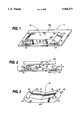
- FIG. 1 is a perspective view illustrating a backlighting apparatus constructed in accordance with the invention
- FIG. 2 is a side elevation view illustrating the mode of operation of the backlighting apparatus of FIG. 1 in conjunction with an LCD;
- FIG. 3 is a perspective view illustrating the light pipe utilized in the apparatus of FIG. 1.
- I provide an improved liquid crystal display (LCD) assembly.
- the assembly includes a LCD and a means for backlighting the LCD.
- the backlighting means includes a printed circuit board; a light pipe mounted on the printed circuit board and having a wing spaced about the circuit board and including a light reflective surface canted with respect to the circuit board; and, a light generating die mounted on the circuit board intermediate the wing and the circuit board. Light from the die travels upwardly away from the circuit board and toward and into the wing, and reflects off of the reflective surface in directions of travel generally parallel to the circuit board and the LCD to travel into the light pipe to backlight the LCD.
- I provide an improved light pipe assembly.
- the light pipe assembly includes a printed circuit board; includes a light pipe mounted on the printed circuit board and having a light reflective surface canted with respect to the circuit board; and, includes a light generating die mounted on the circuit board. Light from the die travels upwardly away from the circuit board towards and into the wing. The light reflects off of the reflective surface in directions of travel generally parallel to the circuit board.
- the light pipe assembly includes a light transparent member having a bottom, an upper light output surface, and a side portion including a light reflective surface canted to reflect light into the light transparent member toward the upper light output surface.
- the light is provided by a die positioned beneath the bottom, the side portion, and the upper light output surface of the transparent member to transmit light through the bottom and against the light reflective surface for reflection inwardly generally toward the upper light output surface.
- FIGS. 1 to 3 illustrate a backlight assembly constructed in accordance with the principles of the invention.
- the backlighting apparatus of FIGS. 1 and 2 includes a printed circuit board 11, light pipe 10 mounted on board 11, and dies 12 and 13 mounted on board 11.
- One or more dies 12 can be mounted on board 11 beneath surface 16.
- One or more dies 13 can be mounted on board 11 beneath surface 19.
- Wires 14 and 15 supply electrical energy to dies 12 and 13, respectively, to cause the dies to produce light which travels upwardly into light pipe 10.
- Light pipe 10 includes an upper light output surface 10, canted rectangular light reflective surfaces 22 and 23, and a bottom portion.
- Surfaces 22 and 23 are preferably canted at an acute angle 31 of thirty to sixty degrees with respect to surface 16 and to circuit board 11.
- the bottom portion of light pipe 10 includes light transparent rectangular surfaces 16, 19, 20, and 21 and light reflective surfaces 17 and 18.
- surfaces 16 and 22 bound the triangular left hand wing or side of light pipe 10.
- Rectangular surfaces 19 and 23 bound the triangular right hand wing or side of light pipe 10.
- the wings or ends of pipe 10 can take on any desired shape or dimension.
- Light pipe 10 is formed of a transparent material like glass or a transparent plastic such as an acrylic or polystyrene. Surfaces 17, 18, 22 and 23 of light pipe 10 are coated with an opaque white paint or other light reflective material. Light generated by die 12 travels upwardly through transparent surface 16 into the left hand wing of pipe 10. Light from die 12 traveling into the left hand wing of pipe 10 is reflected from surface 22 in the manner indicated by arrows 26 and 27 in FIG. 2. As the reflected light travels inwardly into pipe 10 from surface 22, the light travels toward surface 24 and in directions generally parallel to upper light output surface 24 and to the circuit board 11. Some of the light reflected from surface 22 is also subsequently reflected off of surface 17 upwardly toward surface 24 in the manner indicated by arrow 26 in FIG. 2.
- Surfaces 17 and 18 perform the important function of increasing the concentration or strength of light near the center 30 of surface 24 such that the intensity of light emitted from surface 24 tends to be uniform at each point on surface 24.
- a die 13 can be positioned beneath board 11 in the manner indicated by dashed lines 13A in FIG. 2. Light from a die 13A would travel upwardly through an aperture formed in board 11, through transparent surface 19, and off of surface 23 toward the center 30 of pipe 10. Light reflected from surface 23 travels toward surface 24 in paths generally parallel to output surface 24 and board 11. As used herein, paths of travel of light reflected from surfaces 22, 17, 18, 23 are parallel to surface 24 and board 11 if said paths are at an angle 33 to surface 24 and board 11 of thirty degrees or less. While the light beam indicated by arrow 27 in FIG. 2 is travelling toward and parallel to surface 24, surface 22 (and 23) can be canted such that light travels in a direction of travel upwardly to surface 24 or travels in a direction of travel directly toward surface 17 to be reflected upwardly directly toward surface 24.
- the apparatus of FIG. 1 is used to backlight a LCD by placing the upper light output surface 24 adjacent a LCD 25 in the well known fashion illustrated in FIG. 2.
- the height A of pipe 10 is in the range of 0.010 to 0.250 inch, is preferably in the range of 0.080 to 0.150 inch.
- the use of dies 12 and 13 is critical in the practice of the invention. A die typically only costs one cent, which is much less than other light generating devices used to backlight a LCD.
- the term "die” indicates any substrate comprised of a semiconductor material like silicon that is doped to generate light when electrical current is applied to the die.
- a die comprises a component of a LED (light emitting diode) and does not, standing alone, comprise a LED.
- a "LED” includes a clear epoxy encapsulate placed over a die to "pot” or “mold” the die and to form a convex housing which disperses and spreads light emanating from the die.
- a single wire or electrical lead is ordinarily attached to the die to cause light to emanate from the die.
- the die can be driven by a current supplying circuit.
- light travels from the die 12, through air, and through surface 16. Or, light can travel from the die directly through surface 16 if the die is very close to surface 16.
- the space between die 12 and surface 16 is in the range of 0.00003937 inch to 0.500 inch, preferably 0.005 to 0.100 inch.
- Dies 12 and 13 are not incandescent lamps or fiber optic cables.
- the height of a die 12 to 13 equals the distance the die and board wire extends above board 11 and is typically 0.005 to 0.050 of an inch.
- the small size of a die 12 to 13 is critical in the invention because it permits the die to be placed beneath pipe 10 on board 11 so that light can travel upwardly from the die into the bottom of pipe 10 and through surface 16 thereof.
- the formation of pipe 10 to permit a die 12 to be housed intermediate surface 11 and circuit board 11 is also important in enabling the backlighting apparatus of the invention to have a low height or profile indicated by arrows A.
- the height of light pipe 10 is in the range of 0.010 to 0.250 inch and is preferably in the range of 0.080 to 0.150 inch. When the height of the light pipe 10 is less than 0.010 inch, the invention typically does not generate a great enough concentration of light at surface 24. For example, a height A of 0.006 inch is not acceptable.
- LEDs When LEDs are utilized as a source of light for a light pipe, the LEDs are typically placed at the side, and not beneath, the light pipe. Placing the LED at the side of the light pipe consumes significantly more space on a printed circuit board than the backlighting apparatus of the invention. And, importantly, an LED typically costs seven cents while a die costs only a penny.
- the Blackington patent discussed above also teaches the process of directing light into a light pipe through a side wall of the light pipe.
Abstract
Description
Claims (2)
Priority Applications (1)
| Application Number | Priority Date | Filing Date | Title |
|---|---|---|---|
| US08/018,273 US5404277A (en) | 1993-02-16 | 1993-02-16 | Apparatus for backlighting LCD |
Applications Claiming Priority (1)
| Application Number | Priority Date | Filing Date | Title |
|---|---|---|---|
| US08/018,273 US5404277A (en) | 1993-02-16 | 1993-02-16 | Apparatus for backlighting LCD |
Publications (1)
| Publication Number | Publication Date |
|---|---|
| US5404277A true US5404277A (en) | 1995-04-04 |
Family
ID=21787103
Family Applications (1)
| Application Number | Title | Priority Date | Filing Date |
|---|---|---|---|
| US08/018,273 Expired - Lifetime US5404277A (en) | 1993-02-16 | 1993-02-16 | Apparatus for backlighting LCD |
Country Status (1)
| Country | Link |
|---|---|
| US (1) | US5404277A (en) |
Cited By (28)
| Publication number | Priority date | Publication date | Assignee | Title |
|---|---|---|---|---|
| US5608553A (en) * | 1995-07-24 | 1997-03-04 | Samsung Display Devices Co., Ltd. | Back light for a liquid crystal display |
| US5617251A (en) * | 1994-12-26 | 1997-04-01 | Stanley Electric Co., Ltd. | Flat lighting device |
| GB2318444A (en) * | 1996-09-07 | 1998-04-22 | Telefunken Microelectron | Illuminated display arrangement |
| US5748389A (en) * | 1996-09-30 | 1998-05-05 | Motorola, Inc. | Optical pedestal and method for using the same |
| US5779339A (en) * | 1996-01-17 | 1998-07-14 | Stanley Electric Co., Ltd. | Surface light source apparatus |
| US5907222A (en) * | 1993-11-03 | 1999-05-25 | Litton Systems, Inc. | High efficiency backlighting system for rear illumination of electronic display devices |
| US5917655A (en) * | 1998-04-06 | 1999-06-29 | Motorola, Inc. | Method and apparatus for generating a stereoscopic image |
| US5982493A (en) * | 1998-06-02 | 1999-11-09 | Motorola, Inc. | Apparatus and method for acquiring multiple images |
| US6238076B1 (en) | 1999-03-29 | 2001-05-29 | Primetech Electronics, Inc. | Compact light mixing and diffusing apparatus |
| US20030116079A1 (en) * | 2001-12-26 | 2003-06-26 | Yazaki Corporation | Dial plate, its manufacturing method, meter using the same, in-vehicle status indicator and meter using the same |
| US6626551B2 (en) * | 2000-02-25 | 2003-09-30 | Seiko Epson Corporation | Lighting device, and electronic device using the same |
| US20040080924A1 (en) * | 2002-10-25 | 2004-04-29 | Toppoly Optoelectronics Corp. | Light module and flat panel display including the light module |
| US20040183774A1 (en) * | 1999-03-12 | 2004-09-23 | Seiji Manabe | Surface lighting device and portable terminal using the same |
| US20040212981A1 (en) * | 2003-04-28 | 2004-10-28 | Toppoly Optoelectronics Corp. | LED lighting module |
| US20050135082A1 (en) * | 2003-11-27 | 2005-06-23 | Funai Electric Co., Ltd. | Electronic device |
| US20060250542A1 (en) * | 2005-05-04 | 2006-11-09 | Au Optronics Corp. | Backlight structure |
| US20070080626A1 (en) * | 2005-10-11 | 2007-04-12 | Seung-Hyun Son | Light emitting device using electron emission and flat display apparatus using the same |
| US20080043491A1 (en) * | 2006-08-16 | 2008-02-21 | Gigno Technology Co., Ltd. | Light emitting unit and light guiding element thereof |
| US20080151539A1 (en) * | 2006-12-26 | 2008-06-26 | Hung-Lin Lee | Indicator light device |
| US20090046455A1 (en) * | 2006-03-06 | 2009-02-19 | Koji Yoshino | Optical display device |
| US20090225531A1 (en) * | 2007-02-02 | 2009-09-10 | Praiswater Michael R | Night vision imaging system (NVIS) compliant backlight |
| US20100226146A1 (en) * | 2009-03-06 | 2010-09-09 | Chunghwa Picture Tubes, Ltd. | Backlight module |
| US20110134360A1 (en) * | 2008-07-22 | 2011-06-09 | Sharp Kabushiki Kaisha | Illumination unit, illumination device, and liquid crystal display apparatus |
| EP2423718A2 (en) | 2010-08-25 | 2012-02-29 | Young Lighting Technology Corporation | Light guide plate and light source module |
| US20120188787A1 (en) * | 2011-01-24 | 2012-07-26 | Johnson Controls Technology Company | System for illuminating a vehicle interior assembly |
| US10310169B2 (en) * | 2015-05-14 | 2019-06-04 | Boe Technology Group Co., Ltd. | Display panel backlight unit with light guide plate shaped to cover light source |
| US10739513B2 (en) | 2018-08-31 | 2020-08-11 | RAB Lighting Inc. | Apparatuses and methods for efficiently directing light toward and away from a mounting surface |
| US10801679B2 (en) | 2018-10-08 | 2020-10-13 | RAB Lighting Inc. | Apparatuses and methods for assembling luminaires |
Citations (11)
| Publication number | Priority date | Publication date | Assignee | Title |
|---|---|---|---|---|
| US3780357A (en) * | 1973-02-16 | 1973-12-18 | Hewlett Packard Co | Electroluminescent semiconductor display apparatus and method of fabricating the same |
| US3883772A (en) * | 1972-05-02 | 1975-05-13 | Matsushita Electronics Corp | Electric light-emitting apparatus |
| US4257084A (en) * | 1979-02-21 | 1981-03-17 | Reynolds Christopher H | Display device |
| US4528617A (en) * | 1982-02-08 | 1985-07-09 | Sheltered Workshop For The Disabled, Inc. | Light distribution apparatus |
| US4698730A (en) * | 1986-08-01 | 1987-10-06 | Stanley Electric Co., Ltd. | Light-emitting diode |
| US4714983A (en) * | 1985-06-10 | 1987-12-22 | Motorola, Inc. | Uniform emission backlight |
| JPS63293506A (en) * | 1987-05-26 | 1988-11-30 | Teikoku Tsushin Kogyo Kk | Illuminating device for liquid crystal display element |
| US4845595A (en) * | 1987-07-31 | 1989-07-04 | Mitsubishi Jidosha Kogyo Kabushiki Kaisha | Meter device for vehicle |
| US4929062A (en) * | 1988-11-02 | 1990-05-29 | Motorola, Inc. | Light guide for LCD |
| US4959759A (en) * | 1989-08-04 | 1990-09-25 | Delco Electronics Corporation | Automotive instrument display having a thickfilm electroluminescent lightpipe pointer |
| US5008788A (en) * | 1990-04-02 | 1991-04-16 | Electronic Research Associates, Inc. | Multi-color illumination apparatus |
-
1993
- 1993-02-16 US US08/018,273 patent/US5404277A/en not_active Expired - Lifetime
Patent Citations (11)
| Publication number | Priority date | Publication date | Assignee | Title |
|---|---|---|---|---|
| US3883772A (en) * | 1972-05-02 | 1975-05-13 | Matsushita Electronics Corp | Electric light-emitting apparatus |
| US3780357A (en) * | 1973-02-16 | 1973-12-18 | Hewlett Packard Co | Electroluminescent semiconductor display apparatus and method of fabricating the same |
| US4257084A (en) * | 1979-02-21 | 1981-03-17 | Reynolds Christopher H | Display device |
| US4528617A (en) * | 1982-02-08 | 1985-07-09 | Sheltered Workshop For The Disabled, Inc. | Light distribution apparatus |
| US4714983A (en) * | 1985-06-10 | 1987-12-22 | Motorola, Inc. | Uniform emission backlight |
| US4698730A (en) * | 1986-08-01 | 1987-10-06 | Stanley Electric Co., Ltd. | Light-emitting diode |
| JPS63293506A (en) * | 1987-05-26 | 1988-11-30 | Teikoku Tsushin Kogyo Kk | Illuminating device for liquid crystal display element |
| US4845595A (en) * | 1987-07-31 | 1989-07-04 | Mitsubishi Jidosha Kogyo Kabushiki Kaisha | Meter device for vehicle |
| US4929062A (en) * | 1988-11-02 | 1990-05-29 | Motorola, Inc. | Light guide for LCD |
| US4959759A (en) * | 1989-08-04 | 1990-09-25 | Delco Electronics Corporation | Automotive instrument display having a thickfilm electroluminescent lightpipe pointer |
| US5008788A (en) * | 1990-04-02 | 1991-04-16 | Electronic Research Associates, Inc. | Multi-color illumination apparatus |
Cited By (39)
| Publication number | Priority date | Publication date | Assignee | Title |
|---|---|---|---|---|
| US5907222A (en) * | 1993-11-03 | 1999-05-25 | Litton Systems, Inc. | High efficiency backlighting system for rear illumination of electronic display devices |
| US5617251A (en) * | 1994-12-26 | 1997-04-01 | Stanley Electric Co., Ltd. | Flat lighting device |
| US5608553A (en) * | 1995-07-24 | 1997-03-04 | Samsung Display Devices Co., Ltd. | Back light for a liquid crystal display |
| US5779339A (en) * | 1996-01-17 | 1998-07-14 | Stanley Electric Co., Ltd. | Surface light source apparatus |
| GB2318444A (en) * | 1996-09-07 | 1998-04-22 | Telefunken Microelectron | Illuminated display arrangement |
| US5748389A (en) * | 1996-09-30 | 1998-05-05 | Motorola, Inc. | Optical pedestal and method for using the same |
| US5917655A (en) * | 1998-04-06 | 1999-06-29 | Motorola, Inc. | Method and apparatus for generating a stereoscopic image |
| US5982493A (en) * | 1998-06-02 | 1999-11-09 | Motorola, Inc. | Apparatus and method for acquiring multiple images |
| US8144088B2 (en) | 1999-03-12 | 2012-03-27 | Panasonic Corporation | Surface lighting device and portable terminal using the same |
| US7088333B1 (en) * | 1999-03-12 | 2006-08-08 | Matsushita Electric Industrial Co., Ltd. | Surface lighting device and portable terminal using the same |
| US20040183774A1 (en) * | 1999-03-12 | 2004-09-23 | Seiji Manabe | Surface lighting device and portable terminal using the same |
| US20090160758A1 (en) * | 1999-03-12 | 2009-06-25 | Panasonic Corporation | Surface lighting device and portable terminal using the same |
| US7492346B2 (en) | 1999-03-12 | 2009-02-17 | Panasonic Corporation | Surface lighting device and portable terminal using the same |
| US6238076B1 (en) | 1999-03-29 | 2001-05-29 | Primetech Electronics, Inc. | Compact light mixing and diffusing apparatus |
| US6626551B2 (en) * | 2000-02-25 | 2003-09-30 | Seiko Epson Corporation | Lighting device, and electronic device using the same |
| US20040052066A1 (en) * | 2000-02-25 | 2004-03-18 | Seiko Epson Corporation | Lighting device, and electronic device using the same |
| US6820994B2 (en) | 2000-02-25 | 2004-11-23 | Seiko Epson Corporation | Lighting device, and electronic device using the same |
| US20030116079A1 (en) * | 2001-12-26 | 2003-06-26 | Yazaki Corporation | Dial plate, its manufacturing method, meter using the same, in-vehicle status indicator and meter using the same |
| US6817310B2 (en) * | 2001-12-26 | 2004-11-16 | Yazaki Corporation | Dial plate, its manufacturing method, meter using the same, in-vehicle status indicator and meter using the same |
| US6871975B2 (en) * | 2002-10-25 | 2005-03-29 | Toppoly Optoelectronics Corp. | Light module and flat panel display including the light module |
| US20040080924A1 (en) * | 2002-10-25 | 2004-04-29 | Toppoly Optoelectronics Corp. | Light module and flat panel display including the light module |
| US20040212981A1 (en) * | 2003-04-28 | 2004-10-28 | Toppoly Optoelectronics Corp. | LED lighting module |
| US7198379B2 (en) * | 2003-11-27 | 2007-04-03 | Funai Electric Co., Ltd. | Lens for electronic device and disk device having same |
| US20050135082A1 (en) * | 2003-11-27 | 2005-06-23 | Funai Electric Co., Ltd. | Electronic device |
| US20060250542A1 (en) * | 2005-05-04 | 2006-11-09 | Au Optronics Corp. | Backlight structure |
| US20070080626A1 (en) * | 2005-10-11 | 2007-04-12 | Seung-Hyun Son | Light emitting device using electron emission and flat display apparatus using the same |
| US7748884B2 (en) * | 2006-03-06 | 2010-07-06 | Sony Corporation | Display illumination device with light sensor |
| US20090046455A1 (en) * | 2006-03-06 | 2009-02-19 | Koji Yoshino | Optical display device |
| US20080043491A1 (en) * | 2006-08-16 | 2008-02-21 | Gigno Technology Co., Ltd. | Light emitting unit and light guiding element thereof |
| US20080151539A1 (en) * | 2006-12-26 | 2008-06-26 | Hung-Lin Lee | Indicator light device |
| US20090225531A1 (en) * | 2007-02-02 | 2009-09-10 | Praiswater Michael R | Night vision imaging system (NVIS) compliant backlight |
| US20110134360A1 (en) * | 2008-07-22 | 2011-06-09 | Sharp Kabushiki Kaisha | Illumination unit, illumination device, and liquid crystal display apparatus |
| US20100226146A1 (en) * | 2009-03-06 | 2010-09-09 | Chunghwa Picture Tubes, Ltd. | Backlight module |
| US8210700B2 (en) * | 2009-03-06 | 2012-07-03 | Chunghwa Picture Tubes, Ltd. | Backlight module |
| EP2423718A2 (en) | 2010-08-25 | 2012-02-29 | Young Lighting Technology Corporation | Light guide plate and light source module |
| US20120188787A1 (en) * | 2011-01-24 | 2012-07-26 | Johnson Controls Technology Company | System for illuminating a vehicle interior assembly |
| US10310169B2 (en) * | 2015-05-14 | 2019-06-04 | Boe Technology Group Co., Ltd. | Display panel backlight unit with light guide plate shaped to cover light source |
| US10739513B2 (en) | 2018-08-31 | 2020-08-11 | RAB Lighting Inc. | Apparatuses and methods for efficiently directing light toward and away from a mounting surface |
| US10801679B2 (en) | 2018-10-08 | 2020-10-13 | RAB Lighting Inc. | Apparatuses and methods for assembling luminaires |
Similar Documents
| Publication | Publication Date | Title |
|---|---|---|
| US5404277A (en) | Apparatus for backlighting LCD | |
| US7029156B2 (en) | Light emitting apparatus and display | |
| US7385653B2 (en) | LED package and backlight assembly for LCD comprising the same | |
| US7163322B2 (en) | Illumination device for license plate | |
| KR930004409B1 (en) | Surface lighting apparatus | |
| JP4143920B2 (en) | Surface light source device and display device using the same | |
| US20050045897A1 (en) | Light emitting apparatus | |
| JP2000011723A (en) | Sheet-like lighting system | |
| US20120051093A1 (en) | Light Guide with Embedded Light Sources | |
| KR20060107923A (en) | Light emitting panel | |
| US20020136502A1 (en) | Lighting device | |
| JP2001035230A (en) | Flat lighting system | |
| CN111025743B (en) | Light source module and display device | |
| US10823362B2 (en) | Vehicular lamp fitting | |
| US5377083A (en) | Surface illuminator | |
| JP2001067919A (en) | Planar light source unit | |
| EP1873444A1 (en) | Planar lighting apparatus | |
| KR20030064628A (en) | Planar light source apparatus | |
| US20240084981A1 (en) | Lighting module, lighting device and lamp | |
| WO1989005524A1 (en) | Planar led illuminant | |
| JPH0237322A (en) | Panel light emitting device | |
| JP2000348517A (en) | Light emitting device | |
| JPH0615006U (en) | Planar light emitter | |
| KR100810888B1 (en) | Lamp housing assembly | |
| JP2558443Y2 (en) | Surface lighting device |
Legal Events
| Date | Code | Title | Description |
|---|---|---|---|
| STCF | Information on status: patent grant |
Free format text: PATENTED CASE |
|
| AS | Assignment |
Owner name: THREE-FIVE SYSTEMS, INC., ARIZONA Free format text: ASSIGNMENT OF ASSIGNORS INTEREST;ASSIGNOR:LINDBLAD, EDWARD W.;REEL/FRAME:007492/0947 Effective date: 19950427 |
|
| FPAY | Fee payment |
Year of fee payment: 4 |
|
| FPAY | Fee payment |
Year of fee payment: 8 |
|
| REMI | Maintenance fee reminder mailed | ||
| AS | Assignment |
Owner name: SILICON VALLEY BANK, CALIFORNIA Free format text: SECURITY AGREEMENT;ASSIGNOR:THREE-FIVE SYSTEMS, INC.;REEL/FRAME:015612/0328 Effective date: 20040625 |
|
| AS | Assignment |
Owner name: THREE-FIVE SYSTEMS, INC., ARIZONA Free format text: RELEASE;ASSIGNOR:SILICON VALLEY BANK;REEL/FRAME:018398/0012 Effective date: 20060207 |
|
| REMI | Maintenance fee reminder mailed | ||
| FEPP | Fee payment procedure |
Free format text: PAYER NUMBER DE-ASSIGNED (ORIGINAL EVENT CODE: RMPN); ENTITY STATUS OF PATENT OWNER: SMALL ENTITY Free format text: PAYOR NUMBER ASSIGNED (ORIGINAL EVENT CODE: ASPN); ENTITY STATUS OF PATENT OWNER: SMALL ENTITY |
|
| FPAY | Fee payment |
Year of fee payment: 12 |
|
| SULP | Surcharge for late payment |
Year of fee payment: 11 |
|
| AS | Assignment |
Owner name: CHI MEI OPTOELECTRONICS CORPORATION, TAIWAN Free format text: ASSIGNMENT OF ASSIGNORS INTEREST;ASSIGNOR:THREE-FIVE SYSTEMS, INC.;REEL/FRAME:021651/0850 Effective date: 20080815 |
|
| AS | Assignment |
Owner name: CHIMEI INNOLUX CORPORATION,TAIWAN Free format text: MERGER;ASSIGNOR:CHI MEI OPTOELECTRONICS CORP.;REEL/FRAME:024380/0141 Effective date: 20100318 Owner name: CHIMEI INNOLUX CORPORATION, TAIWAN Free format text: MERGER;ASSIGNOR:CHI MEI OPTOELECTRONICS CORP.;REEL/FRAME:024380/0141 Effective date: 20100318 |
|
| FEPP | Fee payment procedure |
Free format text: PAYER NUMBER DE-ASSIGNED (ORIGINAL EVENT CODE: RMPN); ENTITY STATUS OF PATENT OWNER: SMALL ENTITY Free format text: PAYOR NUMBER ASSIGNED (ORIGINAL EVENT CODE: ASPN); ENTITY STATUS OF PATENT OWNER: SMALL ENTITY |
|
| AS | Assignment |
Owner name: INNOLUX CORPORATION, TAIWAN Free format text: CHANGE OF NAME;ASSIGNOR:CHIMEI INNOLUX CORPORATION;REEL/FRAME:032589/0585 Effective date: 20121219 |