US5386781A - Parachute deployment system - Google Patents
Parachute deployment system Download PDFInfo
- Publication number
- US5386781A US5386781A US07/976,207 US97620792A US5386781A US 5386781 A US5386781 A US 5386781A US 97620792 A US97620792 A US 97620792A US 5386781 A US5386781 A US 5386781A
- Authority
- US
- United States
- Prior art keywords
- parachute
- warhead
- drogue
- ignition
- main
- Prior art date
- Legal status (The legal status is an assumption and is not a legal conclusion. Google has not performed a legal analysis and makes no representation as to the accuracy of the status listed.)
- Expired - Fee Related
Links
Images


Classifications
-
- F—MECHANICAL ENGINEERING; LIGHTING; HEATING; WEAPONS; BLASTING
- F42—AMMUNITION; BLASTING
- F42B—EXPLOSIVE CHARGES, e.g. FOR BLASTING, FIREWORKS, AMMUNITION
- F42B4/00—Fireworks, i.e. pyrotechnic devices for amusement, display, illumination or signal purposes
- F42B4/26—Flares; Torches
- F42B4/28—Parachute flares
Definitions
- the present invention is related to a parachute deployment system for use with a rocket-motor propelled warhead. More particularly, the present invention is related to a parachute deployment system which implements the use of a main parachute pack and a drogue parachute pack for use with an illuminating flare warhead.
- Flares of various types have found useful application to accomplish a variety of purposes. For military purposes, for example, it is often desirable to light a particular area at night. A flare may be used to produce light for search and rescue operations, or for various other military purposes. When used in these applications, flares are typically mounted to a rocket motor and launched to a predetermined target area. A parachute is generally mounted to the flare and designed to deploy over the target area, thereby permitting the flare to slowly descend while emitting light.
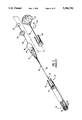
- Typical of prior-art flares is the M-257 Standoff Illuminating Flare, made for the U.S. Army, and designated generally at 10 in FIGS. 1 through 4.
- the end of the flare 10 includes a motor adapter 12 upon which a rocket motor may be threadably attached.
- the flare 10 further includes a fuse 14, a drogue parachute 16, a main parachute 18, flare illuminant 20 and an illuminant ignition system 22.
- Fuse 14 housed within the motor adapter 12, is armed upon initial acceleration of the rocket motor.
- the M-257 employs what is commonly referred to as a "setback fuse” which includes a slider 24 which is of sufficient mass that it compresses a spring 26 upon initial acceleration of the rocket motor.
- Rocket motors commonly employed in propelling such flares generally have an initial acceleration of about 60 g-forces (approximately 770 m/s 2 ) over a period of about one second.
- the slider 24 Upon burn-out of the rocket motor, the slider 24 is forced back to the position illustrated in FIG. 1 by the extension force of the spring 26. Upon reaching the end of its travel, the slider 24 releases a firing pin which fires a primer cap (not shown).
- the primer cap is positioned contiguous a pyrotechnic delay column (not shown) such that firing of the primer cap ignites the delay column.
- the delay column burns for a predetermined period of time, generally about nine seconds, while the flare is coasting through the air. While coasting, the flare slows from its maximum velocity of about 2200 ft/sec to about 750 ft/sec.
- a propellant wafer 28 which acts as the first separation charge.
- the separation charge is ignited.
- the firing of the separation charge results in the buildup of a pressure of approximately 5,000 psi.
- a pusher plate 32 bears against the aft end of the drogue parachute housing 34, thereby tending to separate the warhead from the rocket motor.
- the force of separation resulting from the internal pressure buildup causes shear pins 30 which attach the motor adapter 12 to the remainder of the flare to shear.
- shearing of shear pins 30 the motor adapter 12 and rocket motor are released from the warhead, as illustrated in FIG. 2.
- the pusher plate 32 Upon separation, the pusher plate 32 falls away from the main parachute housing and becomes subject to the substantial resistance forces imposed by the atmosphere.
- the pusher plate 32 is attached to the drogue chute 16. Hence, the force of air resistance on the pusher plate 32 pulls the drogue chute 16 out of the housing 34 and permits it to inflate.
- a deflector plate 36 attached to the motor adapter 12, falls off to the side of the motor adapter 12.
- the force of air resistance acting on the deflector plate 36 causes the deflector plate 36 to function as a drogue and alter the trajectory of the combined motor adapter 12 and the rocket motor, thereby assisting to prevent the possible collision of the rocket motor with the flare.
- the deflector plate 36 does not always induce adequate lateral forces on the rocket motor and collision with the flare occasionally does occur.
- a gas generator 38 mounted within the parachute housing 34, is ignited upon deployment of the drogue parachute 16.
- a nylon cord or wire 40 connects the bridle 42 of the drogue parachute 16 to a "quick match" 44 located inside the gas generator 38.
- the cord or wire 40 is shorter than the main drogue line 46; thus, as the droque parachute deploys, the quick match 44 is pulled out of the gas generator 38 and ignition of the generator is effected.
- the gas generator 38 acts as a delay to control how long the drogue parachute is deployed. In the M-257 standard flare, the gas generator 38 provides an approximate two-second delay.
- the head end of the gas generator 38 is positioned contiguous a propellant wafer 48 which functions as a secondary separation charge. Thus, as the gas generator 38 burns out, it ignites the propellant wafer 48.
- the secondary separation charge generates an internal pressure of about 10,000 psi. This pressure causes a second pusher plate 50 to bear against the aft end of the main parachute housing 52 and results in the shearing of shear pins 54 which attach the drogue chute housing 34 to the main chute housing 52. As the shear pins 54 are broken, the drogue chute 16 and the drogue chute housing 34 are separated from the remainder of the flare, as illustrated in FIG. 3.
- the second pusher plate 50 then falls out and is exposed at high speed to the atmosphere.
- the resulting force of air resistance on the second pusher plate 50 deploys a pilot parachute 56 to which the second pusher plate 50 is attached.
- the pilot parachute 56 is connected to a main parachute container 58 in which the main parachute 18 is housed.
- the force on the main parachute container 58 resulting from the deployment of the pilot parachute 56 causes the main parachute container 58 to be extracted from the main parachute housing 52.
- the line 60 connecting the pilot chute 56 to the main parachute housing 52 and the main parachute line 62 are fully extended, the force of the resulting jerk is sufficient to break the cotton ties 64 which hold the main chute 18 within the main chute container 58.
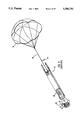
- the main parachute 18 is deployed, as illustrated in FIG. 4. With the main parachute deployed, the flare descends at an approximate rate of 13 ft/sec.
- the flare ignition system 22 is armed upon initial acceleration of the flare.
- the forces due to the acceleration of the flare cause a "zig zag" safety block 70 to compress a spring 72.
- the safety block 70 and spring 72 are concentrically mounted about a mounting column.
- the safety block 70 includes a pawl which rides in a zig-zag shaped track located within the mounting column.
- the flare In order for the safety block to follow the track and completely compress the spring, the flare must have an acceleration of 22 g-forces over a period of about one second. Thus, should the rocket motor malfunction and not fully accelerate, the flare ignition system will not arm.
- the flare is ignited by pulling an ignition lanyard 74.
- the ignition lanyard is attached at one end to the main chute line 62 and at the other end to the ignition system 22.
- the ignition lanyard passes from the main chute line to the ignition system along a raceway between the illuminant 20 and the canister.
- the lanyard is attached to a slider 78.
- the ignition lanyard 74 Upon deployment of the main parachute 18 (FIG. 3), the ignition lanyard 74 is pulled, causing the slider 78 to move across its track.
- a hammer (not shown) is retracted against a spring as the slider 78 is pulled across its track. As the slider 78 reaches the end of its track, the hammer is released and, under the force of the spring, strikes a primer cap which fires into a pellet basket 80 containing a number of BKNO 3 pellets.
- a layer of foam 82 serves to tightly pack the pellets as a guard against vibration of the pellets.
- the heat from the pellets ignites the propellant wafer 84.. Ignition of the pellets and wafer 84 generates sufficient heat to ignite the flare illuminant 20 at the head end of the flare.
- the internal gas pressure generated upon ignition of the wafer 84 blows the ignition system 22 off of the flare (FIG. 4), leaving the flare open to the atmosphere and permitting the approximate 1 million candle power of light generated by the flare to shine out of the flare canister and onto the area to be illuminated.
- M-257 flare One of the principal disadvantages of the M-257 flare is its size.
- the M-257 is 31.6 inches long. It is often desirable to launch flares out of standardized rocket launchers, such as those carried by military aircraft. Unlike most standardized 70 mm warheads, the M-257 extends about eight inches out of the launcher, precluding the use of aerodynamic fairings on the launcher to improve aircraft performance and protect the payload from environmental and electronic radiation hazards. Additionally, the length of the M-257 prohibits the use of standardized 70 mm packaging and logistic system with the flare.
- a warhead out of such a rocket launcher works best if the warhead is less than 27 inches long.
- One way of reducing the length of the flare warhead is to reduce the amount of illuminant contained within the flare. This solution is obviously disadvantageous because it significantly effects the performance of the warhead. Most standardized flares are designed to produce 120 seconds of continuous illumination at one million candlepower of intensity. It would be most advantageous if these performance parameters could be maintained.
- the M-257 is designed to work with a fixed-delay fuse.
- This fuse provides a constant delay of 13.5 seconds from launch to flare ignition. This corresponds to a fixed standoff range of about 4,200 meters from launcher to target and a fixed parachute deployment velocity of 250 m/sec.
- variable range flare In recent years, however, the demand for a variable range flare has resulted in the development of variable delay fuses.
- the range of the flare is thus controlled by utilizing a fuse which can vary the time between when the rocket motor fires and when the drogue parachute deploys.
- the parachutes must be capable of being deployed over a wide range of velocities.
- the force on the ignition lanyard resulting from the deployment of the main parachute may be insufficient to trigger the firing of the ignition system.
- the extreme jerk on the ignition lanyard frequently results in the lanyard being broken without pulling the slider and triggering ignition of the ignition system.
- the present invention is directed to a novel parachute deployment system for use with a flare warhead which is propelled by a rocket motor.
- the parachute deployment system of the present invention utilizes a compact two-stage parachute system.
- the parachute system includes a drogue parachute housed within a drogue parachute pack and a main parachute housed within a main parachute pack.
- the two parachute packs are positioned in a detached, side-by-side relationship.
- the parachute packs are positioned within the warhead in a side-by-side, detached relationship with respect to each other.
- an extraction line connects the drogue parachute pack to the motor adapter.
- a pusher plate is also employed between the separation charge and the parachute packs and is attached to the extraction line.
- the parachute packs are positioned within the warhead and are connected to each other only by means of sequencing lines which control the sequence in which the parachute packs are extracted from the warhead. Importantly, the parachute packs are extracted from the warhead one at a time.
- the sequencing lines are configured such that upon firing of the separation charge and separation of the rocket motor from the warhead, the drogue parachute pack is initially extracted, followed by the extraction of the main parachute pack. Seriatim extraction of the parachute packs requires a lesser force than simultaneous extraction, as simultaneous extraction results in a substantial vacuum being generated within the warhead which must be overcome in order for extraction to be achieved.
- the extraction line becomes taut.
- the resulting force tending to continue to separate the rocket motor from the warhead is sufficient to break cotton ties which hold the drogue parachute within its pack. After these cotton ties break, the drogue parachute is pulled from its pack and inflates.
- the drogue parachute cover acts as a deflector, preventing the rocket motor from colliding into the warhead.
- the pusher plate acts in combination with the drogue parachute cover as a deflector. Utilizing the drogue parachute pack as a deflector, either with or without the pusher plate, results in improved performance over that achieved by prior-art configurations.
- the drogue parachute As the drogue parachute deploys, it triggers a time-delayed line cutter which is attached to one of the sequencing lines.
- the time delay provided by the line cutter controls how long the drogue parachute is deployed.
- the line cutter Upon expiration of the time delay within the line cutter, the line cutter severs the sequencing line to which it is attached.
- the load imposed by the drogue parachute is then transferred to the main parachute cover.
- Cotton ties holding the main parachute within the main parachute cover immediately break under the force of the load imposed by the drogue parachute. This detaches the drogue parachute from the warhead and permits the main parachute to deploy.
- an ignition lanyard is attached to the bridle of the main parachute. Because of the novel configuration of the parachute deployment system of the present invention, all forces acting on the warhead during deployment of the parachute system are transmitted through the main parachute bridle. With the ignition lanyard attached to the main bridle, multiple redundancies are built into the flare ignition system.
- the parachute deployment system of the present invention is designed to successfully deploy over a wide range of velocities, such as is required when using a variable range fuse.
- the flare ignition system may be triggered at any time commencing with the separation of the rocket motor from the warhead to the deployment of the main parachute.
- FIG. 1 is a perspective view of a prior-art M-257 warhead, with portions cut away to more particularly illustrate some of the features of its parachute deployment system.
- FIG. 2 is a perspective view of the warhead of FIG. 1 with the drogue parachute deployed and portions of the flare canister cut away.
- FIG. 3 is a perspective view of the warhead of FIG. 1 with the pilot parachute deployed and portions of the flare canister cut away.
- FIG. 4 is a perspective view of the warhead of FIG. 1 with the main parachute deployed and portions of the flare canister cut away.
- FIG. 5 is a perspective view of one embodiment of the parachute deployment system of the present invention, with portions of the flare canister cut away to more particularly illustrate the invention.
- FIG. 6 is a perspective view of a flare warhead including the parachute deployment system of FIG. 5 and mounted on a typical rocket motor, showing the warhead in the initial moments of launch.
- FIG. 7 is a perspective view of the flare warhead of FIG. 6 following the firing of the separation charge.
- FIG. 8 is a perspective view of the flare warhead of FIG. 6 as the parachute packs are extracted, with portions cut away to more clearly illustrate the invention.
- FIG. 9 is a perspective view of the flare warhead of FIG. 6 immediately following drogue deployment, with portions cut away to more clearly illustrate the invention.
- FIG. 9A is a perspective view taken along line 9A--9A of FIG. 9 immediately prior to the inflation of the drogue parachute, with portions cut away to more clearly illustrate the invention.
- FIG. 9B is a perspective view of the components of the invention illustrated in FIG. 9A immediately following the inflation of the drogue parachute, with portions cut away to more clearly illustrate the invention.
- FIG. 10 is a perspective view of the components of the invention illustrated in FIG. 9A immediately following the firing of the line cutter, with portions cut away to more clearly illustrate the invention.
- FIG. 11 is a perspective view of the flare warhead of FIG. 6 upon inflation of the main parachute, with portions cut away to more clearly illustrate the invention.
- FIG. 12 is a perspective view of the flare warhead of FIG. 6 following deployment of the main parachute.
- FIG. 13 is a partially exploded perspective view of a flare warhead configured with an alternative embodiment of the parachute deployment system of the present invention, with portions cut away to more clearly illustrate the invention.
- FIG. 14 is a perspective view of the warhead of FIG. 13 following deployment of the main parachute, with portions cut away to more clearly illustrate the invention.
- FIG. 15 is a cross-sectional view taken along line 15--15 of FIG. 14, illustrating the exploding bolt assembly.
- the flare warhead 100 includes a motor adapter 102, a fuse 104, a two-stage parachute system 106, flare illuminant 108 and an illuminant ignition system 110.
- Motor adapter 102 is that conventionally known for use with military warheads, and will generally include threads 112 which are used to threadably connect the warhead 100 to a rocket motor.
- Fuse 104 may be a conventionally known remote-set fuse and fits within the bore of the motor adapter 102.
- a coaxial umbilical cable 114 permits the fuse to be set from a remote location, such as from the cockpit of a helicopter or airplane.
- the umbilical cable 114 mates with the launching aircraft control system and is electrically connected to the fuse 104 via a flat cable passing through or under a raceway 116 located between the illuminant 108 and the flare canister 118. Holes (not shown) are drilled through the top and bottom of the ignition system 110 to allow passage of the cable 114.
- the parachute deployment system of the present invention is ideally suited for use with variable range fuses in that it may successfully deploy over a range of velocities from about 250 m/s to about 1,000 m/s. These velocities generally correspond to a standoff range from about 1,000 to about 15,000 meters.
- a threaded plug (not shown) in the aft end of the motor adapter 102.
- a threaded plug provides additional access to install and connect the fuse.
- the plug provides access to permit the fuse to be manually removed in the event emergency disarming of the flare is necessary.
- fuse 104 is armed upon initial acceleration of the rocket motor.
- Fuse 104 includes a slider 120 which is of sufficient mass that it compresses a spring 122 upon acceleration of the rocket motor. Upon burn-out of the rocket motor, the slider 120 is forced back to the position illustrated in FIG. 5 by the extension force of the spring 122.
- the slider 120 releases a firing pin which strikes a priming cap (not shown) and causes it to fire.
- the priming cap is positioned contiguous a pyrotechnic delay column (not shown) such that firing of the priming cap ignites the delay column.
- the delay column burns for a predetermined period of time, generally about nine seconds, while the flare is coasting through the air. As the delay column burns out, it ignites a separation charge 124.
- variable range fuse accomplishes through electrical means the same result as does the standard set-back fuse 104.
- an electronic delay sets the coast time.
- the desired coast time is a function of how far the flare should travel before deployment of the drogue parachute.
- the variable range fuse causes the separation charge to ignite.
- the flare warhead 110 may also include a standard ignition system 110, such as that described in connection with the M-257 illustrated in FIG. 1.
- the ignition system 110 includes a "zig-zag" safety block 130 which compresses a spring 132 upon initial acceleration of the rocket motor, thereby arming the ignition system 110. With the zig-zag safety block 130 retracted, a slider 134 may be pulled across its track by an ignition lanyard 136.
- the ignition lanyard is positioned in raceway 116 and is connected to the main parachute bridle, as will be explained below in further detail.
- the slider 134 retracts and releases a spring-loaded hammer which fires a priming cap into a BKNO 3 pellet basket 138.
- BKNO 3 pellets magnesium/teflon pellets may also be used.
- the firing of the BKNO 3 pellet basket 138 fires a propellant wafer 142.
- the firing of the propellant wafer 142 creates sufficient heat that the illuminant 108 is ignited.
- the firing of the propellant wafer 142 creates sufficient gas pressure that the ignition system 110 is blown off the end of the flare, thereby permitting the light generated by the burning illuminant 108 to shine out of the canister 118 and illuminate the area below the flare.
- the flare warhead 100 is initially connected to a rocket motor 150 which, when fired, accelerates the warhead to a maximum velocity.
- the separation charge is fired a predetermined period of time following burnout of the rocket motor, as determined by the particular fuse employed.
- the gas pressure within the fuse cavity causes a pusher plate 144 (FIG. 5) to bear against the aft end 146 of the parachute housing 180.
- the loads generated by the gas pressure result in the shearing of shear pins 151.
- the size and number of shear pins 151 employed is a function of the gas pressure generated upon the firing of the separation charge 124, and may be readily determined by one of skill in the art.
- the separation charge 124 comprises a 5.1 to 5.5 gram charge of M-9 propellant which is sufficient to shear up to twelve 0.125 inch diameter aluminum shear pins 151.
- the warhead of the present invention has only one pinned joint. Consequently, the complete rocket round is more stable in flight than the M-257.
- an extraction line 152 connects the pusher plate 144 to the motor adapter 102.
- the extraction line 152 is preferably a metal cable which is attached to the motor adapter 102 by a threaded fitting.
- the extraction line 152 is attached to the pusher plate by passing the line through a hole in the pusher plate 144 and sealing the hole with a quick-curing polyurethane adhesive 154.
- any polymeric sealant may be employed, including epoxy and polyester sealants.
- the extraction line 152 is terminated at the head end of the pusher plate 144 with a metal ball 156 which aids in equilibrating the distribution of forces from the extraction line 152 on the pusher plate 144.
- a pair of wires (not shown) are also passed through the hole in the pusher plate 144 before it is sealed to connect the fuse stake-pins and the contacts to the flat cable which passes along the raceway 116 from the umbilical cable 114.
- the hole within the pusher plate 144 must be sealed to prevent the hole from acting as a nozzle. If the hole is not entirely sealed, there exists the possibility that, upon firing of the separation charge 124, high-temperature gasses will pass through the hole and be concentrated on the parachute packs or the cables positioned adjacent the pusher plate 144.
- the two-stage parachute system 106 includes a drogue parachute pack 160 and a main parachute pack 162.
- the drogue parachute pack 160 includes a drogue parachute 164 which is housed within a drogue chute cover 166.
- the main parachute pack 162 includes a main parachute 168 which is housed within a main chute cover 170.
- the drogue chute cover 166 and the main chute cover 170 are preferably made of Kevlar® cloth with an aluminized coating, thereby permitting them to resist any heat which may leak past the pusher plate 144.
- a main drogue line 171 serves to connect the drogue parachute pack 160 to the main parachute pack 162, as is explained below in greater detail.
- the preferred two-stage parachute system 106 is a modified version of a parachute system designed by Pioneer Aerospace of South Windsor, Conn.
- the two-stage parachute system utilized with the present invention permits the chute packs to be extracted from the parachute housing 180 one at a time. Seriatim extraction of the chute packs prevents a substantial vacuum from being generated within the warhead and thereby requires a lesser force to extract the parachute packs than does simultaneous extraction.
- a drogue extraction line 172 attaches the drogue parachute pack 160 to the pusher plate 144.
- the drogue extraction line 172 is a Kevlar® rope.
- the drogue extraction line 172 is attached to the pusher plate 144 by cow hitching it to a mounting plate-174 which is mounted onto the pusher plate 144.
- the mounting plate 174 is preferably mounted to the pusher plate 144 by means of two rivets 176 and is positioned such that the drogue extraction line 172 and the extraction line 152 are substantially collinear when taut.
- the pusher plate 144 may be configured with the extraction line 152 and the drogue extraction line 172 each attached to the center of the pusher plate 144, these lines may be mounted in other locations on the pusher plate 144 so long as they are mounted on substantially the same location on the pusher plate 144, thereby ensuring they remain in a collinear relationship. If the drogue extraction line 172 is not collinear with the extraction line 152, the extraction line 152 will bend at the aft end 177 of the pusher plate 144 when the line is loaded. Consequently, stress risers at that point in the extraction line 152 may be sufficient to sever the line and cause the attempted extraction of the drogue parachute pack 160 to fail.
- the drogue extraction line 172 is attached to the drogue parachute pack 160 by cow hitching it to a drogue cover strap 178.
- the drogue parachute pack 160 and the main parachute pack 162 are positioned within the parachute housing 180 in a detached relationship.
- the drogue parachute pack 160 is initially extracted from the parachute housing 180 when the extraction line 152 and the drogue extraction line 172 become fully extended.
- the rocket motor 150, motor adapter 102 and pusher plate 144 act unitedly as an extraction implement which is separated from the warhead to promote deployment of the parachute system.
- the main drogue line 171 extends out of the head end of the drogue parachute pack 160 and into the aft end of the main parachute pack 162. Thus, upon extraction of the drogue parachute pack 160 from the parachute housing 180, the main drogue line 171 causes the main parachute pack 162 to also be extracted.
- the main parachute pack 162 is connected to the flare via a main parachute line 182 which is attached to a bulkhead 184 at the aft end of the illuminant 108.
- Parachute line 182 is preferably a 4,000-lb Kevlar® line, although a steel line may also be used. At this point in the deployment process, both parachute packs are extracted from the parachute housing 180, but no parachutes have yet deployed (compare FIGS. 8 and 9).
- the ignition lanyard 136 is attached to the main parachute line 182 by crimping it around the main bridle 210.
- the length of the ignition lanyard 136 is measured to be shorter than the length of the main chute line 182.
- the ignition lanyard 136 may be pulled hard enough to trigger the ignition system 110 before any parachutes deploy.
- the drogue parachute 164 As the drogue parachute 164 is inflated, it exerts a substantial jerk on all the lines connecting the drogue parachute 164 to the bulkhead 184. Thus, if the flare ignition system 110 has not yet been triggered, the force on the ignition lanyard 136 resulting from the deployment of the drogue parachute 164 may be sufficient to trigger the ignition system 110. As soon as the ignition lanyard 136 is pulled with sufficient force to trigger the flare ignition system 110, the main chute line 182 then supports the entire load imposed by the drogue parachute 164.
- both the drogue chute cover 166 and the pusher plate 144 are subjected to the substantial forces of wind resistance imposed by the atmosphere.
- the drogue chute cover 166 and the pusher plate 144 generally are forced alongside the motor adapter 102, as illustrated in FIG. 9, where they act as a motor deflector.
- the aerodynamic forces acting on the drogue chute cover 166 and the motor adapter 102 give rise to radial forces which act on the rocket motor and cause the rocket motor to deviate from the path being traveled by the flare 100, thereby preventing the rocket motor from colliding with the flare 100.
- the drogue chute line 171 is attached to a drogue bridle 200 to which are attached two drogue loops 202.
- the drogue loops 202 also connect to secondary loops 206 which include within their loop the main cover strap 204.
- a Kevlar® sequencing line 208 connects the drogue loops 202 to a main bridle 210.
- the main chute line 182 also is attached to the main bridle 210.
- the sequencing line 208 passes through a line cutter 212, located within the main chute cover 170.
- the line cutter includes an internal timer and cutting mechanism which actuates to sever the sequencing line 208 a predetermined amount of time following the triggering of the line cutter 208.
- the line cutter 208 provides an approximate four second delay.
- the line cutter 208 may be selected with such delay time as is appropriate for the particular application for which the parachute deployment system is to be used.
- the line cutter 212 is triggered by rapidly extracting a quick match or trigger wire 214 from the line cutter 212.
- the quick match or trigger wire 214 is connected to the main bridle 210 such that upon inflation of the drogue parachute 164, the sequencing line 208 becomes fully extended thereby rapidly separating the line cutter 212 and the quick match 214 (compare FIGS. 9A and 9B).
- the drogue loops 202 are solely supported by the main cover strap 204. These loads are transferred to the main chute cover 170, causing the cotton ties 216 which hold the main chute cover 170 together to break. As the cotton ties 216 break, the main parachute 168 is stripped out of the main chute cover 170 and inflates.
- the main parachute 168 is supported by a plurality of shroud lines 218 which are attached to a main line 220.
- the main parachute 168 has a 52 inch diameter.
- Main line 220 is preferably made of high-strength Kevlar® and is attached at its opposite end to a swivel 222.
- the swivel 222 must be capable of supporting at least 500 pounds, such as the X8R swivel made by the Sampo Division of Rome Industries of Barneveld, N.Y.
- the resulting jerk and tension in the main parachute line 182 is again transferred to the ignition lanyard 136. If the ignition lanyard 136 has not already been pulled with sufficient force to trigger the firing of the ignition system 110, the substantial force of deceleration imposed by the inflation of the main parachute 168 is generally sufficient to trigger the firing of the ignition system 110.
- the firing of the propellant wafer within the ignition system generates internal gas pressure which blows the ignition system off the head end of the flare 100 and ignites the illuminant 108.
- most rocket motors include fins which impart substantial rotational velocities to the warhead.
- these rotational velocities are approximately 22 rev/sec.
- the swivel 222 thus permits the flare 100 to continue to rotate while preventing the shroud lines 218 from twisting together and collapsing the main parachute 168.
- Illuminant 108 may include any of a variety of burnable compositions known in the art, including those which generate visible or infrared light.
- One composition suitable for use as the illuminant is the Thiolite® illuminant, manufactured by Thiokol Corporation.
- Thiolite® illuminant manufactured by Thiokol Corporation.
- compositions for generating smoke or other obscurants may readily be substituted for the illuminant.
- the flare 100 of FIG. 5 is 26.87 inches long and has a diameter of 2.75 inches.
- the aft end borelet 228 acts as a bore rider in the launch tube and has a diameter of 2.79 inches.
- the length of the flare is reduced to less than 27 inches.
- FIG. 13 An alternative embodiment of the parachute deployment system of the present invention is illustrated at 250 in FIG. 13. This embodiment is designed particularly for use with flare warheads utilizing a nose cone, as the parachute deployment system permits the total length of the warhead to be decreased even more than in the previously described embodiment.
- a warhead 252 incorporating the parachute deployment system 250 includes a fuse (not shown) housed within a motor adapter 254.
- the fuse in warhead 252 is preferably a remote-set, variable delay fuse, such as the M439 available from Accudyne Corp. of Janesville, Wis.
- the warhead 252 includes a nose cone 256 in which is housed an illuminant igniter 258.
- the nose cone 256 is primarily for enhanced aerodynamic efficiency, providing increased standoff range for the warhead.
- the ogive shape of the nose cone 256 is substantially identical to the nose cone on the M261 Multipurpose Submunition.
- a coaxial umbilical cable 262 extends out of the nose cone 256 and provides electrical connection to the fuse in much the same manner as described in connection with the embodiment of FIGS. 5 through 12.
- a separation charge 264 is positioned contiguous the fuse such that firing of the fuse will ignite the separation charge 264.
- the flare canister 266 is made of 0.050 inch thick 6061-T6 aluminum tubing and is attached to the motor adapter 254 by four shear pins 268. The strength, size and number of shear pins 268 utilized are selected such that they will easily shear when subjected to the shear forces imposed by the gas pressure of the fired separation charge 264.
- Warhead 252 has a maximum flight velocity of 1100 m/s.
- the maximum flight velocity determines the amount of area drag opposing separation and thereby influences the number of shear pins and the size of propellant charge needed to ensure separation.
- Such a separation charge generates only 500 psi of internal gas pressure. By minimizing the gas pressure resulting from the firing of the separation charge, unintentional firing of the separation charge will result in dispersion of parts of no more than 50 feet, in accordance with Insensitive Munition requirements.
- a flexible elastomeric thermal barrier 272 is provided between the separation charge 264 and the parachute system 250 to insulate the parachute system from the hot gasses generated from the firing of the separation charge 264.
- Warhead 252 further employs a novel illuminant ignition system for igniting the illuminant 260 upon the firing of the separation charge 264.
- a novel illuminant ignition system for igniting the illuminant 260 upon the firing of the separation charge 264.
- a complete disclosure of this novel ignition system is provided in U.S. patent application for Combustible Flare Ignition System invented by Evan E. Day and filed on Nov. 12, 1992 as Ser. No. 07/974,746 That disclosure is specifically incorporated herein by this reference.
- the illuminant ignition system includes a Hivelite® pickup charge 280 positioned contiguous the separation charge 264 which is initiated upon the firing of the separation charge 264.
- the pickup charge 280 extends to a continuous thin-layer explosive train 282 such that the shock resulting from the firing of the pickup charge 280 will detonate the explosive train 282.
- the explosive train 282 extends along the canister 266 adjacent the parachute system 250 and the illuminant 260. At the head end of the warhead, the explosive train connects to an output charge 284. Explosive train 282 has a combustion velocity of about 5,000 ft/sec. Thus, the explosive shock from the pickup charge 280 is virtually instantaneously transferred along the length of the warhead to the output charge 284.
- the explosive shock of the explosive train 282 is sufficient to initiate combustion of the output charge 284.
- the output charge 284 transfers the combustion to a BKNO 3 pellet basket 286.
- illuminant ignition proceeds substantially as previously described in connection with the embodiment of FIGS. 5 through 12.
- Parachute deployment system 250 employs the same two-stage parachute system as does the previously described embodiment. Thus, it includes a drogue parachute pack 290, having a drogue parachute and a drogue parachute cover 292, positioned in a side-by-side, detached relationship with a main parachute pack 294 which includes a main parachute and a main parachute cover 296.
- the extraction line 298 extends past the pickup charge 280 and the thermal barrier 272 and connects to the drogue parachute cover 292.
- the extraction line 298 extracts the drogue parachute pack 290 from the canister 266. Further separation causes the main parachute pack 294 to be extracted.
- the cotton ties 300 which hold the drogue parachute within the drogue parachute cover 292 break and permit the drogue parachute to deploy and inflate.
- the drogue parachute cover 292 acts as the motor deflector.
- the drogue parachute cover 292 is subjected to the substantial forces of wind resistance imposed by the atmosphere.
- the wind resistance forces the droque chute cover 292 alongside the motor adapter 254 where it acts as a motor deflector.
- the aerodynamic forces acting on the drogue chute cover 292 cause the rocket motor to deviate from the path being traveled by the flare, thereby preventing the rocket motor from colliding with the flare.
- the main parachute 302 is supported by a main parachute line 304 which connects to an exploding bolt assembly 306 attached to the bulkhead 308.
- the exploding bolt assembly includes a bolt 310 which is mounted in a housing 312 by a snap ring 314.
- a detonator 316 is positioned in the base of bolt 310 and is in open communication with the aft end of the illuminant 260 through an opening 318 in the base plate 317.
- the burning illuminant 260 ignites the detonator 316. Firing of the detonator 316 shatters the neck 322 of the bolt 310, thereby releasing the main parachute line 304.
- a tether line 324 is connected at one end to the exploding bolt assembly 306 adjacent cavity 320 and at the other end to the top of the inside of the main parachute 302 (FIG. 14).
- the main parachute 302 upon release of the main parachute line 304, the main parachute 302 is immediately inverted and collapsed.
- the parachute 302 and the empty flare canister 266 quickly fall together to the ground.
- the parachute 302 to the empty flare canister 266 the parachute is not permitted to "float" to the ground. Hence, foreign object debris over the target area is minimized and the risk that the parachute could interfere with aircraft over the target area is reduced.
- tether line for a second main parachute support line which is attached to half of the main parachute shroud lines 326, with the main support line 304 attached to the remainder of the shroud lines 326.
- the warhead 252 has a peak spin rate of approximately 55 revolutions per second.
- the shroud lines 326 of the main parachute 302 will wind together and collapse the main parachute 302.
- the swivel must permit the tether 324 to rotate with the main parachute line 304. Because of the need to incorporate the tether 324 into the swivel assembly, this embodiment does not incorporate a swivel at the main bridle 328.
- the main line 330 connects directly to the bridle 328 rather than connecting to a swivel assembly as with the previously described embodiment.
- the housing 312 of the exploding bolt assembly 306 is configured with a V-groove 332 along its base and a shoulder 334 opposite the V-groove 332.
- Bearings 336 are placed between the housing 312 and the bulkhead 308 such that the bearings 336 ride in the V-groove 332 and against a platform 338 on the base plate 317.
- a second set of bearings 340 ride between a shoulder 342 configured in the bulkhead 308 and shoulder 334 in the housing 312.
- the exploding bolt assembly 306 thus permits the entire housing 312 to rotate relative to the flare canister 266.
- the tether 324 rotates with the main parachute line 304 which is also connected to the housing 312.
- the present invention provides a parachute deployment system which incorporates an improved rocket motor deflector to thereby ensure that the rocket motor will not collide with the flare following its separation from the flare. Also, the present invention provides a novel parachute deployment system which enables the overall length of the warhead to be reduced without reducing the amount of illuminant included within the flare to thereby enable aerodynamic fairings to be used on the launcher and a nose cone to be used on the warhead. Additionally, the present invention provides an improved parachute deployment system which is configured with a novel ignition lanyard mounting to ensure that the flare ignition system is fired regardless of the velocity at which the main parachute is deployed.
Landscapes
- Engineering & Computer Science (AREA)
- General Engineering & Computer Science (AREA)
- Aiming, Guidance, Guns With A Light Source, Armor, Camouflage, And Targets (AREA)
Abstract
Description
Claims (25)
Priority Applications (1)
| Application Number | Priority Date | Filing Date | Title |
|---|---|---|---|
| US07/976,207 US5386781A (en) | 1992-11-12 | 1992-11-12 | Parachute deployment system |
Applications Claiming Priority (1)
| Application Number | Priority Date | Filing Date | Title |
|---|---|---|---|
| US07/976,207 US5386781A (en) | 1992-11-12 | 1992-11-12 | Parachute deployment system |
Publications (1)
| Publication Number | Publication Date |
|---|---|
| US5386781A true US5386781A (en) | 1995-02-07 |
Family
ID=25523864
Family Applications (1)
| Application Number | Title | Priority Date | Filing Date |
|---|---|---|---|
| US07/976,207 Expired - Fee Related US5386781A (en) | 1992-11-12 | 1992-11-12 | Parachute deployment system |
Country Status (1)
| Country | Link |
|---|---|
| US (1) | US5386781A (en) |
Cited By (39)
| Publication number | Priority date | Publication date | Assignee | Title |
|---|---|---|---|---|
| US5887825A (en) * | 1996-10-01 | 1999-03-30 | Mcdonnell Douglas Corporation | Multi-stage parachute release |
| US6386112B1 (en) * | 2001-05-01 | 2002-05-14 | Gregory P. Shelton | Aerial pyrotechnic product with retarded post-explosion descent |
| US6412417B1 (en) | 1999-07-22 | 2002-07-02 | Alliant Techsystems Inc. | Igniter assembly actuated by parachute deployment, and flare containing the same |
| US6626400B1 (en) | 1999-10-18 | 2003-09-30 | William R. Booth | Parachute deployment system and method |
| RU2230288C1 (en) * | 2002-11-21 | 2004-06-10 | Федеральное Государственное унитарное предприятие "Государственное научно-производственное предприятие "Сплав" | Separating jet projectile |
| RU2231016C1 (en) * | 2003-03-17 | 2004-06-20 | Федеральное Государственное унитарное предприятие "Государственное научно-производственное предприятие "Сплав" | Detachable nose cone |
| US20070261542A1 (en) * | 2006-05-09 | 2007-11-15 | Chang Industry, Inc. | Airborne platform protection apparatus and associated system and method |
| US20080110364A1 (en) * | 2006-11-14 | 2008-05-15 | Richards Kevin W | Igniter safe and arm, igniter assembly and flare so equipped and method of providing a safety for an igniter assembly |
| EP1975544A2 (en) | 2007-03-27 | 2008-10-01 | Chemring Defence Germany GmbH | Parachute rocket, in particular parachute signal rocket and/or parachute illumination rocket and method for manufacturing the same |
| WO2009138188A3 (en) * | 2008-05-13 | 2010-07-22 | Rheinmetall Waffe Munition Gmbh | Parachute system for especially ballistically deployed systems |
| US8006936B1 (en) | 2006-05-31 | 2011-08-30 | Farr Iii Warren W | Parachute deployment control |
| US8074919B1 (en) | 2009-10-07 | 2011-12-13 | The Boeing Company | Parachute support and stabilization for helicopter recovery systems |
| US20140007804A1 (en) * | 2011-12-14 | 2014-01-09 | United States Government, As Represented By The Secretary Of The Navy | Water parachute for surface vessel motion impedance |
| WO2014037189A1 (en) * | 2012-09-06 | 2014-03-13 | Rheinmetall Waffe Munition Gmbh, Patente | Flare ammunition body shootable from a portable, recoil-free weapon |
| US20140076131A1 (en) * | 2011-05-05 | 2014-03-20 | Ew Simulation Technology Limited | Self-propelled flying apparatus adapted to emulate a hostile firing action |
| US8708285B1 (en) | 2011-01-11 | 2014-04-29 | The United States Of America As Represented By The Secretary Of The Navy | Micro-unmanned aerial vehicle deployment system |
| DE102013011219B3 (en) * | 2013-07-05 | 2014-06-26 | Rheinmetall Waffe Munition Gmbh | Submunition ejected from a spin-stabilized carrier bullet, in particular illuminated ammunition |
| GB2517445A (en) * | 2013-08-20 | 2015-02-25 | Bae Systems Plc | Illumination Munition |
| EP2840348A1 (en) * | 2013-08-20 | 2015-02-25 | BAE Systems PLC | Illumination munition |
| WO2015025145A1 (en) * | 2013-08-20 | 2015-02-26 | Bae Systems Plc | Illumination munition |
| RU2578431C1 (en) * | 2014-11-20 | 2016-03-27 | Владимир Викторович Черниченко | Engineered ammunition with cumulative combat element |
| US20160209191A1 (en) * | 2013-08-20 | 2016-07-21 | Bae Systems Plc | Common carrier munition |
| US20160209190A1 (en) * | 2013-08-20 | 2016-07-21 | Bae Systems Plc | Frangible munition |
| US9528802B1 (en) * | 2015-11-19 | 2016-12-27 | The United States Of America As Represented By The Secretary Of The Army | Indirect fire munition non-lethal cargo carrier mortar |
| US20170029105A1 (en) * | 2015-07-28 | 2017-02-02 | Northrop Grumman Systems Corporation | Coupling mechanism for aircraft |
| RU170324U1 (en) * | 2016-04-21 | 2017-04-21 | Акционерное общество "Новосибирский завод искусственного волокна" | SEPARATING REACTIVE APPARATUS |
| US9778004B2 (en) | 2013-08-20 | 2017-10-03 | Bae Systems Plc | Smoke payload apparatus |
| US9829288B2 (en) | 2015-09-17 | 2017-11-28 | Orbital Atk, Inc. | Retention clips for safety mechanisms of illumination flares and safety mechanisms |
| US20190186882A1 (en) * | 2017-12-19 | 2019-06-20 | Commissariat A L'energie Atomique Et Aux Energies Alternatives | Distress flare |
| US10337845B2 (en) * | 2016-04-20 | 2019-07-02 | Bae Systems Bofors Ab | Supporting device for dividable parachute grenade |
| US10458765B2 (en) | 2016-04-06 | 2019-10-29 | Bae Systems Bofors Ab | Parachute device for divisible shell |
| GB2573783A (en) * | 2018-05-17 | 2019-11-20 | Bae Systems Plc | Payload activation device |
| US10704868B1 (en) * | 2019-05-28 | 2020-07-07 | The Boeing Company | Non-pyrotechnic flare systems and methods |
| US11015907B2 (en) * | 2016-09-15 | 2021-05-25 | Bae Systems Bofors Ab | Method and arrangement for modifying a separable projectile |
| US11199388B2 (en) | 2018-05-17 | 2021-12-14 | Bae Systems Plc | Payload activation device |
| US11565812B2 (en) | 2018-05-17 | 2023-01-31 | Bae Systems Plc | Payload activation device |
| CN116424560A (en) * | 2023-06-08 | 2023-07-14 | 西安羚控电子科技有限公司 | Unmanned aerial vehicle separating and hanging-preventing mechanism, unmanned aerial vehicle and separation control method thereof |
| US12429318B1 (en) | 2024-06-03 | 2025-09-30 | Raytheon Company | Submunition assembly |
| US12523455B2 (en) | 2024-06-03 | 2026-01-13 | Raytheon Company | Submunition deployment system |
Citations (29)
| Publication number | Priority date | Publication date | Assignee | Title |
|---|---|---|---|---|
| US1621421A (en) * | 1925-11-04 | 1927-03-15 | Expl Des Brevets Kunzer Sa | Apparatus for lighting the landing place from aerial craft |
| US1817503A (en) * | 1929-02-06 | 1931-08-04 | Nat Fireworks Inc | Aerial flare |
| US2271224A (en) * | 1938-06-17 | 1942-01-27 | Robert H Goddard | Parachute attachment for aircraft |
| US2394896A (en) * | 1942-09-17 | 1946-02-12 | Kenney Mfg Co | Aerial flare |
| US2394897A (en) * | 1942-10-01 | 1946-02-12 | Kenney Mfg Co | Aerial flare |
| GB899496A (en) * | 1958-09-29 | 1962-06-27 | Contraves Ag | Improvements in and relating to projectiles |
| US3055300A (en) * | 1956-04-06 | 1962-09-25 | Stoehr Donald | Rocket flare head |
| US3113752A (en) * | 1962-01-23 | 1963-12-10 | Aeronca Mfg Corp | Parachute control apparatus |
| US3221656A (en) * | 1964-03-23 | 1965-12-07 | Adrian P Sutten | Apparatus for high-velocity recovery |
| GB1179804A (en) * | 1967-07-30 | 1970-02-04 | Israel State | Illuminating projectiles |
| US3515362A (en) * | 1968-11-14 | 1970-06-02 | Us Navy | Parachute collapsing mechanism |
| GB1198989A (en) * | 1966-11-22 | 1970-07-15 | Schermuly Ltd | Improvements in Pyrotechnic Devices |
| US3593664A (en) * | 1968-12-26 | 1971-07-20 | Thiokol Chemical Corp | Aerial flare and parachute deployment means therefor |
| US3605624A (en) * | 1969-02-10 | 1971-09-20 | Thiokol Chemical Corp | Castable illuminant flare composition and method for making flare body therewith |
| US3706257A (en) * | 1970-05-11 | 1972-12-19 | Thiokol Chemical Corp | Apparatus for packing a nonfluent composition |
| US3712232A (en) * | 1968-10-23 | 1973-01-23 | Us Navy | Variable delay fuse for aircraft parachute flare |
| US3723206A (en) * | 1969-02-10 | 1973-03-27 | Thiokol Chemical Corp | Castable illuminant flare composition |
| US3736877A (en) * | 1970-09-10 | 1973-06-05 | Us Air Force | Ignition system for a parachute flare |
| US3752077A (en) * | 1970-06-04 | 1973-08-14 | Thiokol Chemical Corp | Release connector for a riser of a parachute flare |
| US3773284A (en) * | 1972-02-25 | 1973-11-20 | Us Army | Controllable multi-stage increasing drag parachute |
| US3829046A (en) * | 1973-03-16 | 1974-08-13 | Us Navy | Programmable, reversible drag, multi-stage parachute |
| US3908938A (en) * | 1972-04-21 | 1975-09-30 | Etudes Et Fab Aeronautiques | Parachute |
| US3946672A (en) * | 1974-08-13 | 1976-03-30 | Thiokol Corporation | Rocket propelled projectile |
| US4029014A (en) * | 1976-02-23 | 1977-06-14 | Thiokol Corporation | Safety igniter for flares |
| US4226185A (en) * | 1977-09-02 | 1980-10-07 | Werkzeugmaschinenfabrik Oerlikon-Buhrle Ag | Projectile with a payload |
| US4649826A (en) * | 1986-03-13 | 1987-03-17 | Morton Thiokol Inc. | Retardation system for air launched flares and submunitions |
| US4765247A (en) * | 1987-07-07 | 1988-08-23 | Morton Thiokol, Inc. | Parachute collapsing system and method for flares |
| US5054398A (en) * | 1989-04-10 | 1991-10-08 | Messerschmitt-Bolkow-Blohm Gmbh | Process and apparatus for dispersing submunition bodies |
| US5239927A (en) * | 1991-07-25 | 1993-08-31 | Rheinmetall Gmbh | Deceleration device for submunition |
-
1992
- 1992-11-12 US US07/976,207 patent/US5386781A/en not_active Expired - Fee Related
Patent Citations (29)
| Publication number | Priority date | Publication date | Assignee | Title |
|---|---|---|---|---|
| US1621421A (en) * | 1925-11-04 | 1927-03-15 | Expl Des Brevets Kunzer Sa | Apparatus for lighting the landing place from aerial craft |
| US1817503A (en) * | 1929-02-06 | 1931-08-04 | Nat Fireworks Inc | Aerial flare |
| US2271224A (en) * | 1938-06-17 | 1942-01-27 | Robert H Goddard | Parachute attachment for aircraft |
| US2394896A (en) * | 1942-09-17 | 1946-02-12 | Kenney Mfg Co | Aerial flare |
| US2394897A (en) * | 1942-10-01 | 1946-02-12 | Kenney Mfg Co | Aerial flare |
| US3055300A (en) * | 1956-04-06 | 1962-09-25 | Stoehr Donald | Rocket flare head |
| GB899496A (en) * | 1958-09-29 | 1962-06-27 | Contraves Ag | Improvements in and relating to projectiles |
| US3113752A (en) * | 1962-01-23 | 1963-12-10 | Aeronca Mfg Corp | Parachute control apparatus |
| US3221656A (en) * | 1964-03-23 | 1965-12-07 | Adrian P Sutten | Apparatus for high-velocity recovery |
| GB1198989A (en) * | 1966-11-22 | 1970-07-15 | Schermuly Ltd | Improvements in Pyrotechnic Devices |
| GB1179804A (en) * | 1967-07-30 | 1970-02-04 | Israel State | Illuminating projectiles |
| US3712232A (en) * | 1968-10-23 | 1973-01-23 | Us Navy | Variable delay fuse for aircraft parachute flare |
| US3515362A (en) * | 1968-11-14 | 1970-06-02 | Us Navy | Parachute collapsing mechanism |
| US3593664A (en) * | 1968-12-26 | 1971-07-20 | Thiokol Chemical Corp | Aerial flare and parachute deployment means therefor |
| US3605624A (en) * | 1969-02-10 | 1971-09-20 | Thiokol Chemical Corp | Castable illuminant flare composition and method for making flare body therewith |
| US3723206A (en) * | 1969-02-10 | 1973-03-27 | Thiokol Chemical Corp | Castable illuminant flare composition |
| US3706257A (en) * | 1970-05-11 | 1972-12-19 | Thiokol Chemical Corp | Apparatus for packing a nonfluent composition |
| US3752077A (en) * | 1970-06-04 | 1973-08-14 | Thiokol Chemical Corp | Release connector for a riser of a parachute flare |
| US3736877A (en) * | 1970-09-10 | 1973-06-05 | Us Air Force | Ignition system for a parachute flare |
| US3773284A (en) * | 1972-02-25 | 1973-11-20 | Us Army | Controllable multi-stage increasing drag parachute |
| US3908938A (en) * | 1972-04-21 | 1975-09-30 | Etudes Et Fab Aeronautiques | Parachute |
| US3829046A (en) * | 1973-03-16 | 1974-08-13 | Us Navy | Programmable, reversible drag, multi-stage parachute |
| US3946672A (en) * | 1974-08-13 | 1976-03-30 | Thiokol Corporation | Rocket propelled projectile |
| US4029014A (en) * | 1976-02-23 | 1977-06-14 | Thiokol Corporation | Safety igniter for flares |
| US4226185A (en) * | 1977-09-02 | 1980-10-07 | Werkzeugmaschinenfabrik Oerlikon-Buhrle Ag | Projectile with a payload |
| US4649826A (en) * | 1986-03-13 | 1987-03-17 | Morton Thiokol Inc. | Retardation system for air launched flares and submunitions |
| US4765247A (en) * | 1987-07-07 | 1988-08-23 | Morton Thiokol, Inc. | Parachute collapsing system and method for flares |
| US5054398A (en) * | 1989-04-10 | 1991-10-08 | Messerschmitt-Bolkow-Blohm Gmbh | Process and apparatus for dispersing submunition bodies |
| US5239927A (en) * | 1991-07-25 | 1993-08-31 | Rheinmetall Gmbh | Deceleration device for submunition |
Non-Patent Citations (4)
| Title |
|---|
| LUU 2B/B Aircraft Deployed Illuminating Flare product brochure , Thiokol corporation, Brigham City, Utah (date unkonw). * |
| LUU.2B/B Aircraft-Deployed Illuminating Flare [product brochure], Thiokol corporation, Brigham City, Utah (date unkonw). |
| M 257 Standoff Illuminating Flare product brochure , Thiokol Corporation, Brigham City, Utah (date unknown). * |
| M-257 Standoff Illuminating Flare [product brochure], Thiokol Corporation, Brigham City, Utah (date unknown). |
Cited By (55)
| Publication number | Priority date | Publication date | Assignee | Title |
|---|---|---|---|---|
| US5887825A (en) * | 1996-10-01 | 1999-03-30 | Mcdonnell Douglas Corporation | Multi-stage parachute release |
| US6412417B1 (en) | 1999-07-22 | 2002-07-02 | Alliant Techsystems Inc. | Igniter assembly actuated by parachute deployment, and flare containing the same |
| US6626400B1 (en) | 1999-10-18 | 2003-09-30 | William R. Booth | Parachute deployment system and method |
| US6386112B1 (en) * | 2001-05-01 | 2002-05-14 | Gregory P. Shelton | Aerial pyrotechnic product with retarded post-explosion descent |
| WO2002088620A1 (en) * | 2001-05-01 | 2002-11-07 | Shelton Gregory P | Aerial pyrotechnic product with retarded post-explosion descent |
| RU2230288C1 (en) * | 2002-11-21 | 2004-06-10 | Федеральное Государственное унитарное предприятие "Государственное научно-производственное предприятие "Сплав" | Separating jet projectile |
| RU2231016C1 (en) * | 2003-03-17 | 2004-06-20 | Федеральное Государственное унитарное предприятие "Государственное научно-производственное предприятие "Сплав" | Detachable nose cone |
| US20070261542A1 (en) * | 2006-05-09 | 2007-11-15 | Chang Industry, Inc. | Airborne platform protection apparatus and associated system and method |
| US8006936B1 (en) | 2006-05-31 | 2011-08-30 | Farr Iii Warren W | Parachute deployment control |
| US20080110364A1 (en) * | 2006-11-14 | 2008-05-15 | Richards Kevin W | Igniter safe and arm, igniter assembly and flare so equipped and method of providing a safety for an igniter assembly |
| US7726243B2 (en) | 2006-11-14 | 2010-06-01 | Alliant Techsystems Inc. | Igniter safe and arm, igniter assembly and flare so equipped and method of providing a safety for an igniter assembly |
| US20090007812A1 (en) * | 2007-03-27 | 2009-01-08 | Arthur Zahn | Parachute rocket, in particular a parachute signaling rocket and/or a parachute flare rocket, and method for their production |
| EP1975544A2 (en) | 2007-03-27 | 2008-10-01 | Chemring Defence Germany GmbH | Parachute rocket, in particular parachute signal rocket and/or parachute illumination rocket and method for manufacturing the same |
| EP1975544A3 (en) * | 2007-03-27 | 2010-04-21 | Chemring Defence Germany GmbH | Parachute rocket, in particular parachute signal rocket and/or parachute illumination rocket and method for manufacturing the same |
| US7752973B2 (en) * | 2007-03-27 | 2010-07-13 | Chemring Defence Germany Gmbh | Parachute rocket, in particular a parachute signaling rocket and/or a parachute flare rocket, and method for their production |
| WO2009138188A3 (en) * | 2008-05-13 | 2010-07-22 | Rheinmetall Waffe Munition Gmbh | Parachute system for especially ballistically deployed systems |
| US8074919B1 (en) | 2009-10-07 | 2011-12-13 | The Boeing Company | Parachute support and stabilization for helicopter recovery systems |
| US8708285B1 (en) | 2011-01-11 | 2014-04-29 | The United States Of America As Represented By The Secretary Of The Navy | Micro-unmanned aerial vehicle deployment system |
| US20140076131A1 (en) * | 2011-05-05 | 2014-03-20 | Ew Simulation Technology Limited | Self-propelled flying apparatus adapted to emulate a hostile firing action |
| US20140007804A1 (en) * | 2011-12-14 | 2014-01-09 | United States Government, As Represented By The Secretary Of The Navy | Water parachute for surface vessel motion impedance |
| US8813671B2 (en) * | 2011-12-14 | 2014-08-26 | The United States Of America As Represented By The Secretary Of The Navy | Water parachute for surface vessel motion impedance |
| WO2014037189A1 (en) * | 2012-09-06 | 2014-03-13 | Rheinmetall Waffe Munition Gmbh, Patente | Flare ammunition body shootable from a portable, recoil-free weapon |
| DE102013011219B3 (en) * | 2013-07-05 | 2014-06-26 | Rheinmetall Waffe Munition Gmbh | Submunition ejected from a spin-stabilized carrier bullet, in particular illuminated ammunition |
| WO2015000691A1 (en) | 2013-07-05 | 2015-01-08 | Rheinmetall Waffe Munition Gmbh | Submunition, in particular luminous munition, that can be discharged from a spin-stabilized carrier projectile |
| WO2015025145A1 (en) * | 2013-08-20 | 2015-02-26 | Bae Systems Plc | Illumination munition |
| US9778004B2 (en) | 2013-08-20 | 2017-10-03 | Bae Systems Plc | Smoke payload apparatus |
| GB2517445A (en) * | 2013-08-20 | 2015-02-25 | Bae Systems Plc | Illumination Munition |
| GB2517445B (en) * | 2013-08-20 | 2020-04-29 | Bae Systems Plc | Illumination munition |
| US20160209191A1 (en) * | 2013-08-20 | 2016-07-21 | Bae Systems Plc | Common carrier munition |
| US20160209190A1 (en) * | 2013-08-20 | 2016-07-21 | Bae Systems Plc | Frangible munition |
| US10030953B2 (en) | 2013-08-20 | 2018-07-24 | Bae Systems Plc | Illumination munition |
| EP3036497B1 (en) | 2013-08-20 | 2018-04-25 | BAE Systems PLC | Illumination munition |
| EP2840348A1 (en) * | 2013-08-20 | 2015-02-25 | BAE Systems PLC | Illumination munition |
| US9797698B2 (en) * | 2013-08-20 | 2017-10-24 | Bae Systems Plc | Common carrier munition |
| AU2014310469B2 (en) * | 2013-08-20 | 2017-10-05 | Bae Systems Plc | Illumination munition |
| US9784544B2 (en) * | 2013-08-20 | 2017-10-10 | Bae Systems Plc | Frangible munition |
| RU2578431C1 (en) * | 2014-11-20 | 2016-03-27 | Владимир Викторович Черниченко | Engineered ammunition with cumulative combat element |
| US20170029105A1 (en) * | 2015-07-28 | 2017-02-02 | Northrop Grumman Systems Corporation | Coupling mechanism for aircraft |
| US9829288B2 (en) | 2015-09-17 | 2017-11-28 | Orbital Atk, Inc. | Retention clips for safety mechanisms of illumination flares and safety mechanisms |
| US9528802B1 (en) * | 2015-11-19 | 2016-12-27 | The United States Of America As Represented By The Secretary Of The Army | Indirect fire munition non-lethal cargo carrier mortar |
| US10458765B2 (en) | 2016-04-06 | 2019-10-29 | Bae Systems Bofors Ab | Parachute device for divisible shell |
| US10337845B2 (en) * | 2016-04-20 | 2019-07-02 | Bae Systems Bofors Ab | Supporting device for dividable parachute grenade |
| RU170324U1 (en) * | 2016-04-21 | 2017-04-21 | Акционерное общество "Новосибирский завод искусственного волокна" | SEPARATING REACTIVE APPARATUS |
| US11015907B2 (en) * | 2016-09-15 | 2021-05-25 | Bae Systems Bofors Ab | Method and arrangement for modifying a separable projectile |
| US10591266B2 (en) * | 2017-12-19 | 2020-03-17 | Commissariat A L'energie Atomique Et Aux Energies Alternatives | Distress flare |
| US20190186882A1 (en) * | 2017-12-19 | 2019-06-20 | Commissariat A L'energie Atomique Et Aux Energies Alternatives | Distress flare |
| GB2573783A (en) * | 2018-05-17 | 2019-11-20 | Bae Systems Plc | Payload activation device |
| US11199388B2 (en) | 2018-05-17 | 2021-12-14 | Bae Systems Plc | Payload activation device |
| US11565812B2 (en) | 2018-05-17 | 2023-01-31 | Bae Systems Plc | Payload activation device |
| GB2573783B (en) * | 2018-05-17 | 2023-03-15 | Bae Systems Plc | Payload activation device |
| US10704868B1 (en) * | 2019-05-28 | 2020-07-07 | The Boeing Company | Non-pyrotechnic flare systems and methods |
| CN116424560A (en) * | 2023-06-08 | 2023-07-14 | 西安羚控电子科技有限公司 | Unmanned aerial vehicle separating and hanging-preventing mechanism, unmanned aerial vehicle and separation control method thereof |
| CN116424560B (en) * | 2023-06-08 | 2023-09-08 | 西安羚控电子科技有限公司 | Unmanned aerial vehicle separating and hanging-preventing mechanism, unmanned aerial vehicle and separation control method thereof |
| US12429318B1 (en) | 2024-06-03 | 2025-09-30 | Raytheon Company | Submunition assembly |
| US12523455B2 (en) | 2024-06-03 | 2026-01-13 | Raytheon Company | Submunition deployment system |
Similar Documents
| Publication | Publication Date | Title |
|---|---|---|
| US5386781A (en) | Parachute deployment system | |
| US5760330A (en) | Method and apparatus for conveying a large-calibre payload over an operational terrain | |
| US4651648A (en) | Pyrotechnic aircraft carried bomb | |
| US4922826A (en) | Active component of submunition, as well as flechette warhead and flechettes therefor | |
| CN101954163B (en) | Intelligent Forest Fire Fighting Aerial Bomb | |
| US7360489B1 (en) | Non-lethal cargo projectile | |
| US5169093A (en) | Method and device for faster automatic deployment of a parachute | |
| US4744301A (en) | Safer and simpler cluster bomb | |
| US20150241181A1 (en) | Munition or projectile for battlefield illumination | |
| US8387507B2 (en) | Weapon interceptor projectile with deployable frame and net | |
| US3930448A (en) | Rocket-deployed balloon for position marker | |
| US4974515A (en) | Warhead | |
| GB2089946A (en) | A practice projectile | |
| US2883910A (en) | Airborne store ejector bolt | |
| US6782829B1 (en) | Non-lethal cargo projectile | |
| US6540176B2 (en) | Fin disengagement device for limiting projectile range | |
| US4327644A (en) | Projectile deployed cable weapons system | |
| US3791300A (en) | Flare shell | |
| US3478687A (en) | Very low descent rate,high intensity,illuminating flare | |
| US3946672A (en) | Rocket propelled projectile | |
| US5347931A (en) | Combustible flare ignition system | |
| US3584581A (en) | Spin launch rectangular-type canister | |
| US2402716A (en) | Antiaircraft shell | |
| US5003881A (en) | Aerial flare and igniter | |
| Smith et al. | Ballute and parachute decelerators for FASM/QUICKLOOK UAV |
Legal Events
| Date | Code | Title | Description |
|---|---|---|---|
| AS | Assignment |
Owner name: THIOKOL CORPORATION, UTAH Free format text: ASSIGNMENT OF ASSIGNORS INTEREST;ASSIGNOR:DAY, EVAN E.;REEL/FRAME:006487/0536 Effective date: 19930219 |
|
| FPAY | Fee payment |
Year of fee payment: 4 |
|
| AS | Assignment |
Owner name: CORDANT TECHNOLOGIES, INC., UTAH Free format text: CHANGE OF NAME;ASSIGNOR:THIOKOL CORPORATION;REEL/FRAME:011712/0322 Effective date: 19980423 |
|
| AS | Assignment |
Owner name: THE CHASE MANHATTAN BANK, NEW YORK Free format text: PATENT SECURITY AGREEMENT;ASSIGNOR:ALLIANT TECHSYSTEMS INC.;REEL/FRAME:011821/0001 Effective date: 20010420 |
|
| AS | Assignment |
Owner name: ALLIANT TECHSYSTEMS INC., MINNESOTA Free format text: ASSIGNMENT OF ASSIGNORS INTEREST;ASSIGNOR:THIOKOL PROPULSION CORP.;REEL/FRAME:012343/0001 Effective date: 20010907 Owner name: THIOKOL PROPULSION CORP., UTAH Free format text: CHANGE OF NAME;ASSIGNOR:CORDANT TECHNOLOGIES INC.;REEL/FRAME:012391/0001 Effective date: 20010420 |
|
| FEPP | Fee payment procedure |
Free format text: PAYOR NUMBER ASSIGNED (ORIGINAL EVENT CODE: ASPN); ENTITY STATUS OF PATENT OWNER: LARGE ENTITY |
|
| FPAY | Fee payment |
Year of fee payment: 8 |
|
| REMI | Maintenance fee reminder mailed | ||
| AS | Assignment |
Owner name: ALLIANT TECHSYSTEMS INC., MINNESOTA Free format text: RELEASE OF SECURITY AGREEMENT;ASSIGNOR:JPMORGAN CHASE BANK (FORMERLY KNOWN AS THE CHASE MANHATTAN BANK);REEL/FRAME:015201/0095 Effective date: 20040331 |
|
| REMI | Maintenance fee reminder mailed | ||
| LAPS | Lapse for failure to pay maintenance fees | ||
| STCH | Information on status: patent discontinuation |
Free format text: PATENT EXPIRED DUE TO NONPAYMENT OF MAINTENANCE FEES UNDER 37 CFR 1.362 |
|
| FP | Lapsed due to failure to pay maintenance fee |
Effective date: 20070207 |