US537874A - walsh - Google Patents
walsh Download PDFInfo
- Publication number
- US537874A US537874A US537874DA US537874A US 537874 A US537874 A US 537874A US 537874D A US537874D A US 537874DA US 537874 A US537874 A US 537874A
- Authority
- US
- United States
- Prior art keywords
- mast
- scow
- walsh
- masts
- new york
- Prior art date
- Legal status (The legal status is an assumption and is not a legal conclusion. Google has not performed a legal analysis and makes no representation as to the accuracy of the status listed.)
- Expired - Lifetime
Links
- 241001421757 Arcas Species 0.000 description 1
- 101710150402 Mastin Proteins 0.000 description 1
- 201000003639 autosomal recessive cerebellar ataxia Diseases 0.000 description 1
Images
Classifications
-
- B—PERFORMING OPERATIONS; TRANSPORTING
- B66—HOISTING; LIFTING; HAULING
- B66C—CRANES; LOAD-ENGAGING ELEMENTS OR DEVICES FOR CRANES, CAPSTANS, WINCHES, OR TACKLES
- B66C23/00—Cranes comprising essentially a beam, boom, or triangular structure acting as a cantilever and mounted for translatory of swinging movements in vertical or horizontal planes or a combination of such movements, e.g. jib-cranes, derricks, tower cranes
- B66C23/18—Cranes comprising essentially a beam, boom, or triangular structure acting as a cantilever and mounted for translatory of swinging movements in vertical or horizontal planes or a combination of such movements, e.g. jib-cranes, derricks, tower cranes specially adapted for use in particular purposes
- B66C23/36—Cranes comprising essentially a beam, boom, or triangular structure acting as a cantilever and mounted for translatory of swinging movements in vertical or horizontal planes or a combination of such movements, e.g. jib-cranes, derricks, tower cranes specially adapted for use in particular purposes mounted on road or rail vehicles; Manually-movable jib-cranes for use in workshops; Floating cranes
- B66C23/52—Floating cranes
Definitions
- YH nonms arcas cu. mom-mms., Mswwcwrv. n4 c inkten STATES lATnNT Ormea.
- My invention relates to improvements in rfloating derricks, and the object of my invention is to provide a floating derrick having two or more masts, by means of which vessels and steamboats can be loaded and unloaded with dispatch, and which can be adjusted in such a manner that each mast fronts a hatch of the vessel to be loaded, and permits the simultaneous loading or unloading from two or more hatches of a vessel.
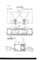
- Figure l is a plan View of the floating derrick.
- Fig. 2 is a longitudinal section through Fig. l on the linea x.
- Fig. 3 is a transverse section through the floating derrick.
- Fig. 4 is alongitudinal section and transverse section of aclamp etnployed in steadying a mast after it has been adjusted.
- a covered scow S is provided with two or more long slots s s, in its deck, each slot hold-- ing a mast M, the foot of which is entered into a pocket in a heavy truck T, guided on wheels t, upon two rails r r, running parallel to the slots s s, one at each side of the truck, preferably through the entire length of the scow and irmly secured to the keelsons of the scow, while above the rails r fr and parallel thereto are arranged two rails p p, under the deck beams, which engage with guide rollers q, on braces o, which are firmly secured to the mast, which braces serve to steadyV the mast when moved in the slot and along the bottom rails fr.
- Each mast M carries preferably two booms M2.
- Both rails fr, and p are connected with each other, and firmly secured in their relative positions by means of tie-rods m, connecting the corresponding rails r and p at each side.
- a clamp C At each side of a mastin the height of the floor-beams, is mounted a clamp C, shown in detail on a larger scale in Fig. 4 of the drawings, which is slightly shorter when drawn in, than the width of a slot s, and which can be tightened by turning a central screw head d, whenever a mast is to be held in a certain position.
- This clamp O consists preferably of two shafts d and cl2 extending upon a common axle in opposite directions from a central screw head d. One of these shafts is provided with right hand screw thread, while the other is provided with left hand screw thread and long square nuts c c2 (shownin section in Fig.
- the masts are preferably located near one side of ascow, as shown in the drawings which illustrate two masts rigged upon a scow, and ballast is placed inthe opposite side to counterbalance their weight.
- ballast is placed inthe opposite side to counterbalance their weight.
- sliding blocks may be employed.
- the operation is then as follows:
- the scowV S is secured alongside a vessel in such a position that one of the masts M, on the scow is placed centrally in front of a hatch of said vessel.
- the clamps O, on the other mast M are then disengaged by turning the head cl, and .the stays at one side of the second mast are disengaged from their fastenings.
- rlhe second mast M is now free to be slid in its slot s, by means of crowbars or hoisting tackle, until it arrives opposite a second hatch of the vessel to be unloaded.
Landscapes
- Engineering & Computer Science (AREA)
- Mechanical Engineering (AREA)
- Saccharide Compounds (AREA)
Description
(No Model.)
J. E. WALSH. PLOATING DERRIGK.
Patented Apr. 23, 1895.
YH: nonms arcas cu. mom-mms., Mswwcwrv. n4 c inkten STATES lATnNT Ormea.
JOHN E. WALSH, OF NEW YORK, N. Y., ASSIGNOR TO MARY A. WALSH, OF
- SAME PLACE.
FLOATING DERRICK.
SPECXFIGATION forming part of Letters Patent N o. 537,874, dated April 23, 1895.
Application tiled November 1'7, 1894. Serial No. 529,145. (No model.)
.To all whom 25V may concern,.-
Be it known that I, JOHN E. WALSH, a citi-p zen of the United States, and a resident of New York, in the county of New York and State of New York, have invented certain new and useful Improvements in Floating Derricks, of which the following is a specification.
My invention relates to improvements in rfloating derricks, and the object of my invention is to provide a floating derrick having two or more masts, by means of which vessels and steamboats can be loaded and unloaded with dispatch, and which can be adjusted in such a manner that each mast fronts a hatch of the vessel to be loaded, and permits the simultaneous loading or unloading from two or more hatches of a vessel. i
In the accompanying drawings, Figure l, is a plan View of the floating derrick. Fig. 2, is a longitudinal section through Fig. l on the linea x. Fig. 3, is a transverse section through the floating derrick. Fig. 4, is alongitudinal section and transverse section of aclamp etnployed in steadying a mast after it has been adjusted.
A covered scow S, is provided with two or more long slots s s, in its deck, each slot hold-- ing a mast M, the foot of which is entered into a pocket in a heavy truck T, guided on wheels t, upon two rails r r, running parallel to the slots s s, one at each side of the truck, preferably through the entire length of the scow and irmly secured to the keelsons of the scow, while above the rails r fr and parallel thereto are arranged two rails p p, under the deck beams, which engage with guide rollers q, on braces o, which are firmly secured to the mast, which braces serve to steadyV the mast when moved in the slot and along the bottom rails fr. Each mast M carries preferably two booms M2.
Both rails fr, and p, are connected with each other, and firmly secured in their relative positions by means of tie-rods m, connecting the corresponding rails r and p at each side.
At both sides of the scow S, are mounted strong eyes or ringbolts n, at regular intervals, which serve to receive the hooks or shackles at the end of the braces or stays b, holding the masts. These stays b, are provided with turn-buckles, to facilitate the shifting of the stays from one position to another.
At each side of a mastin the height of the floor-beams, is mounted a clamp C, shown in detail on a larger scale in Fig. 4 of the drawings, which is slightly shorter when drawn in, than the width of a slot s, and which can be tightened by turning a central screw head d, whenever a mast is to be held in a certain position. This clamp O consists preferably of two shafts d and cl2 extending upon a common axle in opposite directions from a central screw head d. One of these shafts is provided with right hand screw thread, while the other is provided with left hand screw thread and long square nuts c c2 (shownin section in Fig. Ll) are screwed upon the outer ends of the shafts d d2 and left projecting slightly beyond the ends of their respective shafts. The nuts c c2 again are guided and prevented from turning by stirrups E secured to the masts in positions shown in Figs. 1, 2 and 3. It is evident that the turning of a nut d with its connections d d2 in one direction will draw the nuts c' c2 to gether, while turning the nut in thelopposite direction will throw the nuts outward and cause the clamp O to press against the sides of a slot s.
The masts are preferably located near one side of ascow, as shown in the drawings which illustrate two masts rigged upon a scow, and ballast is placed inthe opposite side to counterbalance their weight. AIn place of the rollers t and q, sliding blocks may be employed.
The operation is then as follows: The scowV S, is secured alongside a vessel in such a position that one of the masts M, on the scow is placed centrally in front of a hatch of said vessel. The clamps O, on the other mast M are then disengaged by turning the head cl, and .the stays at one side of the second mast are disengaged from their fastenings. rlhe second mast M is now free to be slid in its slot s, by means of crowbars or hoisting tackle, until it arrives opposite a second hatch of the vessel to be unloaded. The clamps O C, on 'M' are now tightened again and the ends of the stays b, secured to the suitable ringbolts n, at the sides of the scow, and then tightened by means of the turn buckles; when the machine is ready for work. i
Having thus described my invention, I claim- VIOC) In a Hoating derriek, aseow having two slots provided in its deck, two masts in said slots in an upright position, and means for adjusting and securing the same upon said scow in 5 different positions, as and for the purposes herein shown and described.
Signed at New York, in the county of New York and State of New York, this 16th day of November, A. D. 1894.
JOHN E. VALSH.
Witnesses:
ARTHUR M. WIENER, A. T. STEWART.
Publications (1)
| Publication Number | Publication Date |
|---|---|
| US537874A true US537874A (en) | 1895-04-23 |
Family
ID=2606634
Family Applications (1)
| Application Number | Title | Priority Date | Filing Date |
|---|---|---|---|
| US537874D Expired - Lifetime US537874A (en) | walsh |
Country Status (1)
| Country | Link |
|---|---|
| US (1) | US537874A (en) |
-
0
- US US537874D patent/US537874A/en not_active Expired - Lifetime
Similar Documents
| Publication | Publication Date | Title |
|---|---|---|
| CN105658516A (en) | Lashing bridge for a cargo ship | |
| JPS58185389A (en) | Device and method of loading and unloading barge to and from ship | |
| US537874A (en) | walsh | |
| FI60530C (en) | FARTYG FOER TRANSPORT AV CONTAINERS EL DYL | |
| US1207795A (en) | Hay-sling. | |
| CN101346272B (en) | Floating equipment for shipping and transshipment containers | |
| US1084630A (en) | System and apparatus for carrying life and other boats on ships and for launching same therefrom. | |
| US1073794A (en) | Bridge or ferry. | |
| RU2498004C1 (en) | Launch to transport span blocks | |
| CN206203656U (en) | Ships and light boats boom hoisting | |
| US451903A (en) | walsh | |
| DE2651181C3 (en) | Safety device for sailing vehicles | |
| WO2013164039A1 (en) | Pontoon for transporting large and heavy loads | |
| US2442A (en) | Floating dry-dock | |
| US589133A (en) | Ballast-log for vessels | |
| US215136A (en) | khowles | |
| KR100650594B1 (en) | Container Crane Catamaran Container Ship with Combined Gantry Crane | |
| US1460779A (en) | Log raft | |
| US1006044A (en) | Elevator for marine vessels. | |
| US33598A (en) | Improvement in ship-building | |
| US2419361A (en) | Slipway cradle | |
| US124878A (en) | Improvement issj derricks | |
| US3528561A (en) | Apparatus for burtoning cargo | |
| US461606A (en) | Dumping device for vessels | |
| US663763A (en) | Apparatus for making up timber into rafts. |