US5374097A - Universal visor mounting system - Google Patents
Universal visor mounting system Download PDFInfo
- Publication number
- US5374097A US5374097A US08/047,869 US4786993A US5374097A US 5374097 A US5374097 A US 5374097A US 4786993 A US4786993 A US 4786993A US 5374097 A US5374097 A US 5374097A
- Authority
- US
- United States
- Prior art keywords
- visor
- housing
- mirror
- assembly
- visor body
- Prior art date
- Legal status (The legal status is an assumption and is not a legal conclusion. Google has not performed a legal analysis and makes no representation as to the accuracy of the status listed.)
- Expired - Lifetime
Links
- 238000005286 illumination Methods 0.000 claims abstract description 9
- 238000010168 coupling process Methods 0.000 claims abstract description 3
- 238000005859 coupling reaction Methods 0.000 claims abstract description 3
- 230000002093 peripheral effect Effects 0.000 claims description 3
- 230000008878 coupling Effects 0.000 abstract description 2
- 238000010276 construction Methods 0.000 description 6
- 239000000853 adhesive Substances 0.000 description 1
- 230000001070 adhesive effect Effects 0.000 description 1
- 238000004873 anchoring Methods 0.000 description 1
- 230000000712 assembly Effects 0.000 description 1
- 238000000429 assembly Methods 0.000 description 1
- 239000004020 conductor Substances 0.000 description 1
- 238000004519 manufacturing process Methods 0.000 description 1
- 239000000463 material Substances 0.000 description 1
- 238000012986 modification Methods 0.000 description 1
- 230000004048 modification Effects 0.000 description 1
- 229920000515 polycarbonate Polymers 0.000 description 1
- 239000004417 polycarbonate Substances 0.000 description 1
Images


Classifications
-
- B—PERFORMING OPERATIONS; TRANSPORTING
- B60—VEHICLES IN GENERAL
- B60J—WINDOWS, WINDSCREENS, NON-FIXED ROOFS, DOORS, OR SIMILAR DEVICES FOR VEHICLES; REMOVABLE EXTERNAL PROTECTIVE COVERINGS SPECIALLY ADAPTED FOR VEHICLES
- B60J3/00—Antiglare equipment associated with windows or windscreens; Sun visors for vehicles
- B60J3/02—Antiglare equipment associated with windows or windscreens; Sun visors for vehicles adjustable in position
- B60J3/0204—Sun visors
- B60J3/0278—Sun visors structure of the body
-
- B—PERFORMING OPERATIONS; TRANSPORTING
- B60—VEHICLES IN GENERAL
- B60J—WINDOWS, WINDSCREENS, NON-FIXED ROOFS, DOORS, OR SIMILAR DEVICES FOR VEHICLES; REMOVABLE EXTERNAL PROTECTIVE COVERINGS SPECIALLY ADAPTED FOR VEHICLES
- B60J3/00—Antiglare equipment associated with windows or windscreens; Sun visors for vehicles
- B60J3/02—Antiglare equipment associated with windows or windscreens; Sun visors for vehicles adjustable in position
- B60J3/0204—Sun visors
- B60J3/0213—Sun visors characterised by the mounting means
Definitions
- the present invention pertains to vehicle sunvisors and particularly to a system for mounting any one of a variety of different visor bodies using a universal bracket assembly.
- Visors are manufactured in a variety of different shapes depending on the vehicle to which they are mounted. Some visors, for example, are mounted by a single visor mounting elbow bracket at one end while others include different types of auxiliary mounting posts at an end remote from the elbow bracket assembly. Some posts, for example, are mounted within the top edge of the visor body and snap-fit into a clip while others include posts extending axially from the end of the visor to provide additional support for heavier or larger visors and particularly the type which may include illuminated vanity mirror accessories mounted thereto.
- Such visors are typically pre-manufactured and installed by the automobile manufacturer with a given visor configuration being installed in particular vehicle body styles.
- the visors are integrated into a headliner assembly which includes not only the visors but other vehicle accessories such as overhead consoles and the like.
- each visor has a body with a shape designed for the particular vehicle body into which it is to be installed during manufacture of the vehicle.
- the visor mounting system of the present invention permits a single design mounting assembly to accommodate a variety of different, relatively thin, visor body configurations. This construction allows the more costly components of the overall visor assembly to be manufactured efficiently and be used for a variety of different visor body styles used in different vehicles.
- the visor mounting system embodying the present invention can be used with visor bodies of different shapes which include a pocket extending between front and rear surfaces and extending from an upper longitudinally extending edge of the visor body.
- the mounting assembly includes a pivot rod assembly including a torque device which extends within the housing which includes a blade-like frame which extends into the pocket of the visor body and includes means for securing the frame to the visor body.
- the frame includes a mirror assembly.
- the means for attaching the housing to the visor body include snap-in tab means so that different configured visor bodies can be easily attached to the visor mounting assembly during final assembly of a visor for a given vehicle body style.
- the mounting assembly also includes illumination means for the mirror.
- FIG. 1 is an exploded view of the universal visor mounting system shown with three different visor bodies which can be attached to the mounting system;
- FIG. 2 is a front elevational view of a visor including the universal mounting system of the present invention
- FIG. 3 is a front elevational view of the structure shown in FIG. 1, shown with the cover open to expose the mirror;
- FIG. 4 is a rear elevational view of the visor shown in FIGS. 2 and 3;
- FIG. 5 is an exploded perspective view of one embodiment of the visor mounting system embodying the present invention and a visor body used in connection therewith;
- FIG. 6 is an enlarged, fragmentary perspective view of a portion of the universal visor mounting system shown in FIGS. 1-4;
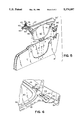
- FIG. 7 is an enlarged, fragmentary perspective view of the opposite end of the visor mounting system shown in FIG. 6;
- FIG. 8 is an enlarged, fragmentary perspective view of the upper rear edge of the visor assembly shown in FIG. 6;
- FIG. 9 is an enlarged, fragmentary perspective view of the upper right corner of the visor mounting assembly shown in FIG. 1, shown with the lens removed;
- FIG. 10 is an enlarged, perspective view of the snap-in lens used in connection with the assembly shown in FIG. 9;
- FIG. 11 is an enlarged, fragmentary right end view of the visor mounting assembly shown in FIG. 1;
- FIG. 12 is a top elevational view of the visor body shown in FIGS. 1-4.
- FIG. 1 there is shown a universal visor mounting system 10 to which there can be snapfitted during assembly, any one of a number of different relatively thin visor bodies 12, 14, or 16, depending upon the vehicle into which the visor formed by the combination of the mounting assembly 10 and one of the visor bodies 12, 14, 16 or other style visor body is mounted.
- Each of the visor bodies 12, 14, and 16 include a front surface 11 and a rear surface 13 having a pocket 15 formed therebetween and extending from the upper longitudinal edge 17 of the visor body.
- the second and third visor body elements are identified by prime (') and double prime (") symbols to differentiate the common elements of the different visor bodies shown.
- the visor body 12 is relatively thin and includes a pocket 15 defined by the spacing between the front wall 11 and rear wall 13 of the visor body shown.
- Each of the visor bodies 12, 14, and 16 may include an auxiliary support such as clip 18 mounted within the visor body 12, outwardly extending post 18' extending from the edge of the upper right corner of visor body 14, or a similar support post 18" extending from a protrusion 19" on visor body 16.
- Each of the different visor bodies 12, 14, and 16 are styled to fit within a particular vehicle body and vehicle interior with the auxiliary posts 18, 18' and 18" (when provided) spaced to fit within a post-receiving socket mounted to the vehicle in a conventional manner for supporting the end of the visor opposite the universal mounting assembly 10.
- a slot or cutout 20 is formed downwardly through the top edge 17 of the visor bodies and into the front wall 11, sufficiently to allow a mirror assembly associated with the visor mounting assembly to be exposed from the front surface of the visor when the visor is in a lowered use position, as shown in FIGS. 2 and 3.
- the visor mounting system 10 includes a housing 50 with an enlarged generally U-shaped channel 52 (FIG. 11) at an upper longitudinal edge for attaching the housing to the visor body and for receiving a visor pivot rod assembly 60 including a torque device 66 (FIGS. 7 and 8).
- the mounting assembly 10 also includes a generally blade-like flat planar frame 56 which integrally extends from one wall of the channel 52 and is shaped to extend within any one of the different visor bodies illustrated in FIG. 1.
- the frame includes means such as tabs 59 for interlocking the frame to a selected visor body.
- FIGS. 2-4 An assembled visor with a body style shown as visor body 12 in FIGS. 1 and 12, is shown in FIGS. 2-4.
- the driver's side visor is shown in what would be a lowered use position with the cover 30 of the preferred embodiment of the visor mounting assembly 10 in a closed position.
- the cover is moved to an open position exposing a mirror 40 for use.
- Mirror 40 is mounted to the frame 56 of housing 50 of the visor mounting assembly 10.
- Mounting assembly 10 also includes an elbow bracket assembly 60 for attachment of the mounting assembly and visor body secured thereto to the vehicle.
- the universal mounting assembly also may include illumination means 70 for selectively providing illumination for use of the mirror 40 when the cover is moved to an open position as shown in FIG. 3.
- the illumination means 70 comprises a pair of lights 90 mounted on opposite sides of the upper portion of the mirror 40 and covered by light diffusing lenses 96 as described in further detail below.
- FIG. 5 two different but related universal mounting assemblies 10 are shown with assembly 10' of FIG. 5 being the same as that shown in FIGS. 1-4 with the exception that it does not include a cover for its mirror 40'.
- Each of the embodiments uses the same visor pivot assembly 60 which, as best seen in FIG. 5, includes a mounting plate 62 for attachment of the visor mounting assembly and visor body secured thereto to a vehicle.
- Mounting plate 62 typically is triangular with three apertures for receiving mounting screws securing the triangular plate and thus the visor to the vehicle.
- snap-in visor mounts may be employed in connection with the visor pivot rod 61.
- the pivot rod includes an elbow 64 and an upwardly extending end 63 which extends into the mounting plate with conventional means for anchoring the end 63 to rotatably mount the pivot rod 61 to the plate 62 for allowing the visor, when in its lowered position, to swivel from a front windshield position to a side window position in a conventional manner.
- the elongated leg of the visor pivot rod 61 is coupled to and extends through a torque device 66 (FIG. 8) which can be of the type described in U.S. Pat. No. 5,004,289.
- the torque device 66 is secured to the housing 50 by a plurality of fasteners 67, as best seen in FIG. 8, for permitting the housing, and the visor body 12 secured thereto, to rotate about the pivot rod 61 between a raised stored position against the vehicle roof and a lowered use position as illustrated in FIGS. 2 and 3.
- Housing 50 includes a generally U-shaped upper channel 52 which, as best seen in FIG. 11, has a top edge 51, a rear wall 53, and a front wall 54 which integrally extends inwardly at opposite ends to define a pair of light receiving sockets in recessed wall areas 55 (FIGS. 6 and 11).
- the front wall 54 also extends downwardly to integrally define a mirror frame 56 into which the mirror 40 is mounted in a conventional manner, as by snap-fitting or by a suitable bonding adhesive.
- the mirror frame 56 which is integral with the front wall 54 of housing 50 circumscribes and holds the mirror in position.
- Frame 56 may include a small recess 57 at its lower edge for allowing access for opening the cover 30.
- the fasteners 67 attach the torque fitting 66 to the back side of the upper portion of the mirror frame, as best seen in FIG. 8.
- Housing 50 includes a pair of pivot axle receiving bosses located in spaced relationship near the top of the housing for pivotally receiving the cover 30. As best seen in FIG. 9, the bosses 32 are located at the inner edge of recessed walls 55 and each receive a pivot axle 34 mounted to the top edge 36 of cover 30 for pivotally mounting the cover to the housing 50. Springs (not shown) are coupled between the housing 50 and cover 30 to assist the movement of the cover between open and closed positions as illustrated in FIGS. 3 and 2, respectively.
- lamps 90 forming part of the illumination means 70 and which are covered by diffusing lenses 96 (FIG. 10).
- the housing includes a recessed wall 55 on each side, as best seen in FIGS. 1-3, with a lens 96 positioned thereover to provide illumination for use of the mirror.
- the lamps 90 are cartridge-type lamps which fit within electrical sockets coupled by means of conductors 92 and 94 (FIG. 11) which extend through the hollow visor pivot rod 61 to the vehicle's electrical system in a conventional manner to selectively apply electrical operating power to the lamps 90.
- a switch will be actuated in a conventional manner for applying operating power to the lamps.
- Housing 50 includes slots 58 (FIG. 9) formed in the sides of recessed wall 55 at spaced locations for receiving tabs 98 on the diffusing lens 96 (FIG. 10) such that the lenses 96 can snap in the housing and be easily removed if necessary to replace the lamps 90.
- a pair of spaced tabs 59 (FIG. 1) are integrally formed at the lower edge of housing 50, and located on the inner bottom edge of frame 56 for engaging slots formed in the rear wall 13 of the visor body 12 for assisting in mounting the assembly 10 to the visor body.
- a single tab 59' is employed and includes posts which interengage the forward wall 11' of the uncovered visor body 12' shown.
- the rear wall 53 of the generally U-shaped top 52 of housing 50 fits over the rear wall 13 of the visor as seen in FIG. 4 with the rear wall 53 of the housing extending along the top edge of the visor, and the front wall 54 extending over the top of the visor body and compressibly engaging the opposed upper edges of the cut-out recess 20 in the visor body, as best seen in FIGS. 2-4.
- the visor mounting assembly 10 is snap-fit within the pocket 15 of the visor body 12 with tabs 59 interlocking the lower portion of the assembly to the visor body and the U-shaped upper member 52 compressibly engaging the top edge of the visor body.
- the peripheral edge of the mirror frame 56 also provides a decorative bezel for the trim appearance of the visor as best seen in FIG. 3.
- the mirror frame 56 includes a peripheral flange 42 which overlies the upholstered outer surface of the visor body 12 to provide a neat trim appearance to the visor when in its assembled position, as seen in FIGS. 2-3.
- the housing may include tabs in addition to the lower tabs 59 which interfit with the rear and or front wall of the visor body for snap-locking the visor body to the universal visor mounting assembly 10 which fits within the pocket 15 of the visor body, regardless of the specific shape of the visor body selected.
- the mounting assembly 10' is substantially the same as the embodiments shown in FIGS. 1-4 but does not include a cover for the vanity mirror 40'.
- other embodiments of the invention may include a mounting assembly 10 which also may not include the illumination means, which in the embodiment shown in FIG. 5 are actuated by a manual switch 41 when it is desired to illuminate the lamps behind lenses 96' on either side of the top of mirror 40'.
- the housing 50 in the preferred embodiment is an integral housing with a generally U-shaped upper member 52 as best seen in FIG. 11, the housing could be formed of multiple sections which are fastened together using conventional fastening means or by snap-fitting together if desired.
- the housing is integrally molded of a suitable polymeric material, such as polycarbonate, to provide the most economical construction for the visor mounting system.
- the configuration of the universal mounting assembly provides the thickest part of the construction at the top of the visor in parallel alignment with the pivot axle axis and a relatively thin, blade-like mirror and supporting frame for coupling to the visor body.
- Such construction allows the visor body itself to be very thin to accommodate easy storage in compact vehicles while still providing an attractive and useful vanity mirror visor which may be covered and illuminated.
Landscapes
- Engineering & Computer Science (AREA)
- Mechanical Engineering (AREA)
- Arrangements Of Lighting Devices For Vehicle Interiors, Mounting And Supporting Thereof, Circuits Therefore (AREA)
Abstract
Description
Claims (11)
Priority Applications (1)
| Application Number | Priority Date | Filing Date | Title |
|---|---|---|---|
| US08/047,869 US5374097A (en) | 1993-04-15 | 1993-04-15 | Universal visor mounting system |
Applications Claiming Priority (1)
| Application Number | Priority Date | Filing Date | Title |
|---|---|---|---|
| US08/047,869 US5374097A (en) | 1993-04-15 | 1993-04-15 | Universal visor mounting system |
Publications (1)
| Publication Number | Publication Date |
|---|---|
| US5374097A true US5374097A (en) | 1994-12-20 |
Family
ID=21951469
Family Applications (1)
| Application Number | Title | Priority Date | Filing Date |
|---|---|---|---|
| US08/047,869 Expired - Lifetime US5374097A (en) | 1993-04-15 | 1993-04-15 | Universal visor mounting system |
Country Status (1)
| Country | Link |
|---|---|
| US (1) | US5374097A (en) |
Cited By (23)
| Publication number | Priority date | Publication date | Assignee | Title |
|---|---|---|---|---|
| EP0695660A3 (en) * | 1994-08-02 | 1996-02-28 | Happich Gmbh Gebr | Sunvisor for vehicle |
| US5498056A (en) * | 1993-11-05 | 1996-03-12 | Gebr. Happich Gmbh | Sun visor for motor vehicles |
| US5716092A (en) * | 1996-06-11 | 1998-02-10 | Prince Corporation | Visor and method of manufacturing |
| US5816642A (en) * | 1997-04-30 | 1998-10-06 | Lear Corporation | Support pin for sun visor |
| US5823603A (en) * | 1995-08-14 | 1998-10-20 | Crotty Corporation | Modular sun visor assembly and method of assembling a sun visor |
| US6003928A (en) * | 1997-10-14 | 1999-12-21 | Lear Automotive Dearborn, Inc. | Interior trim attachment apparatus for an automotive vehicle |
| US6062627A (en) * | 1998-06-17 | 2000-05-16 | Lear Automotive Dearborn, Inc. | No-tabbing visor mounting pin |
| US20020185884A1 (en) * | 2001-05-31 | 2002-12-12 | Llink Technologies, Inc. | Visors for automotive vehicles and methods of forming the same |
| US6543832B1 (en) * | 2002-03-04 | 2003-04-08 | Irvin Automotive Products, Inc. | Modular visor |
| US6604772B2 (en) | 2001-11-09 | 2003-08-12 | Lear Corporation | Extender blade mounting frame for a sun visor |
| US6612552B2 (en) * | 1999-04-16 | 2003-09-02 | William J. Hennessey | Head impact energy absorbing sun visor pivot rod connection interface cover |
| US6619718B1 (en) | 2002-02-25 | 2003-09-16 | Lear Corporation | Modular sun visor and method of assembling same |
| US6637799B1 (en) * | 2002-07-11 | 2003-10-28 | Lear Corporation | Modular sun visor and method of assembling same |
| US6669859B1 (en) | 2003-01-17 | 2003-12-30 | Lear Corporation | Inverted sun visor mirror assembly |
| US20050047159A1 (en) * | 2003-08-25 | 2005-03-03 | Johnson Controls Technology Company | Vanity for a vehicle |
| US20050206186A1 (en) * | 2002-06-02 | 2005-09-22 | Christian Delus | Sun visor for the interior of a motor vehicle |
| USRE39316E1 (en) | 1997-04-14 | 2006-10-03 | Lear Corporation | Sliding visor |
| US20070063528A1 (en) * | 2003-11-05 | 2007-03-22 | Hiroto Ogawa | Vehicle sun visor |
| US20070176459A1 (en) * | 2006-01-17 | 2007-08-02 | Morris Steven E | Reconfigurable sun visor |
| US20090079223A1 (en) * | 2007-09-21 | 2009-03-26 | Irvin Automotive Products, Inc. | D-ring for use with a visor |
| US20090278374A1 (en) * | 2008-05-08 | 2009-11-12 | Toyota Boshoku Kabushiki Kaisha | Vehicle sun visor |
| US9278608B2 (en) | 2014-06-09 | 2016-03-08 | Irvin Automotive Products, Inc. | D-ring for use with a visor |
| US10065483B2 (en) | 2016-10-28 | 2018-09-04 | Teraflex, Inc. | Modular sun visor system |
Citations (21)
| Publication number | Priority date | Publication date | Assignee | Title |
|---|---|---|---|---|
| US2033391A (en) * | 1935-04-04 | 1936-03-10 | Herbert E Muench | Border shade for rear view mirrors |
| CA500350A (en) * | 1954-03-02 | D. Brundage Alan | Visor | |
| US2915937A (en) * | 1958-03-20 | 1959-12-08 | Wesley L Winchell | Visor |
| US3405969A (en) * | 1966-11-21 | 1968-10-15 | Phillips Petroleum Co | Visor |
| GB1245677A (en) * | 1969-05-16 | 1971-09-08 | British Motor Corp | Motor vehicle sun visors |
| US3716269A (en) * | 1969-05-28 | 1973-02-13 | Happich Gmbh Gebr | Sunvisor, especially for motor driven vehicles |
| US4213169A (en) * | 1978-11-09 | 1980-07-15 | Prince Corporation | Covered visor mirror |
| US4541663A (en) * | 1982-06-12 | 1985-09-17 | Gebr. Happich Gmbh | Dazzle reducing arrangement for illuminated sun visor, particularly for automotive vehicles |
| US4576409A (en) * | 1982-12-17 | 1986-03-18 | Gebr. Happich Gmbh | Sun visor with molded stiffening frame |
| US4623188A (en) * | 1983-11-17 | 1986-11-18 | Gebr. Happich Gmbh | Height adjustable sun visor for automotive vehicles |
| US4668005A (en) * | 1983-06-24 | 1987-05-26 | Gebr. Happich Gmbh | Sun visor for vehicles |
| US4858983A (en) * | 1988-04-04 | 1989-08-22 | White Jay E | Sun visor frame and mounting structure |
| US4984137A (en) * | 1988-11-08 | 1991-01-08 | Nissan Motor Co., Ltd. | Sun visor for automotive vehicle |
| US4989911A (en) * | 1989-08-16 | 1991-02-05 | Prince Corporation | Snap-in visor mount |
| US4999746A (en) * | 1988-04-29 | 1991-03-12 | Autopart Sweden Ab | Sunvisor for motor vehicles |
| US5004289A (en) * | 1989-09-27 | 1991-04-02 | Prince Corporation | Visor torque control |
| US5011211A (en) * | 1988-04-29 | 1991-04-30 | Autopart Sweden Ab | Sun visor for motor vehicles |
| US5011212A (en) * | 1988-11-10 | 1991-04-30 | Gebr. Happich Gmbh | Sun visor and support structure for motor vehicles |
| US5031953A (en) * | 1990-06-18 | 1991-07-16 | Plasta Fiber Industries, Inc. | Visor bracket |
| US5061005A (en) * | 1989-08-16 | 1991-10-29 | Prince Corporation | Snap-in visor mount |
| US5221120A (en) * | 1991-03-09 | 1993-06-22 | Gebr. Happich Gmbh | Recyclable material sun-visor for automotive vehicles |
-
1993
- 1993-04-15 US US08/047,869 patent/US5374097A/en not_active Expired - Lifetime
Patent Citations (21)
| Publication number | Priority date | Publication date | Assignee | Title |
|---|---|---|---|---|
| CA500350A (en) * | 1954-03-02 | D. Brundage Alan | Visor | |
| US2033391A (en) * | 1935-04-04 | 1936-03-10 | Herbert E Muench | Border shade for rear view mirrors |
| US2915937A (en) * | 1958-03-20 | 1959-12-08 | Wesley L Winchell | Visor |
| US3405969A (en) * | 1966-11-21 | 1968-10-15 | Phillips Petroleum Co | Visor |
| GB1245677A (en) * | 1969-05-16 | 1971-09-08 | British Motor Corp | Motor vehicle sun visors |
| US3716269A (en) * | 1969-05-28 | 1973-02-13 | Happich Gmbh Gebr | Sunvisor, especially for motor driven vehicles |
| US4213169A (en) * | 1978-11-09 | 1980-07-15 | Prince Corporation | Covered visor mirror |
| US4541663A (en) * | 1982-06-12 | 1985-09-17 | Gebr. Happich Gmbh | Dazzle reducing arrangement for illuminated sun visor, particularly for automotive vehicles |
| US4576409A (en) * | 1982-12-17 | 1986-03-18 | Gebr. Happich Gmbh | Sun visor with molded stiffening frame |
| US4668005A (en) * | 1983-06-24 | 1987-05-26 | Gebr. Happich Gmbh | Sun visor for vehicles |
| US4623188A (en) * | 1983-11-17 | 1986-11-18 | Gebr. Happich Gmbh | Height adjustable sun visor for automotive vehicles |
| US4858983A (en) * | 1988-04-04 | 1989-08-22 | White Jay E | Sun visor frame and mounting structure |
| US4999746A (en) * | 1988-04-29 | 1991-03-12 | Autopart Sweden Ab | Sunvisor for motor vehicles |
| US5011211A (en) * | 1988-04-29 | 1991-04-30 | Autopart Sweden Ab | Sun visor for motor vehicles |
| US4984137A (en) * | 1988-11-08 | 1991-01-08 | Nissan Motor Co., Ltd. | Sun visor for automotive vehicle |
| US5011212A (en) * | 1988-11-10 | 1991-04-30 | Gebr. Happich Gmbh | Sun visor and support structure for motor vehicles |
| US4989911A (en) * | 1989-08-16 | 1991-02-05 | Prince Corporation | Snap-in visor mount |
| US5061005A (en) * | 1989-08-16 | 1991-10-29 | Prince Corporation | Snap-in visor mount |
| US5004289A (en) * | 1989-09-27 | 1991-04-02 | Prince Corporation | Visor torque control |
| US5031953A (en) * | 1990-06-18 | 1991-07-16 | Plasta Fiber Industries, Inc. | Visor bracket |
| US5221120A (en) * | 1991-03-09 | 1993-06-22 | Gebr. Happich Gmbh | Recyclable material sun-visor for automotive vehicles |
Cited By (35)
| Publication number | Priority date | Publication date | Assignee | Title |
|---|---|---|---|---|
| US5498056A (en) * | 1993-11-05 | 1996-03-12 | Gebr. Happich Gmbh | Sun visor for motor vehicles |
| EP0695660A3 (en) * | 1994-08-02 | 1996-02-28 | Happich Gmbh Gebr | Sunvisor for vehicle |
| US5727837A (en) * | 1994-08-02 | 1998-03-17 | Becker Group Europe Gmbh | Multi-part sun visor body for use in a vehicle |
| US5823603A (en) * | 1995-08-14 | 1998-10-20 | Crotty Corporation | Modular sun visor assembly and method of assembling a sun visor |
| US5716092A (en) * | 1996-06-11 | 1998-02-10 | Prince Corporation | Visor and method of manufacturing |
| US5860690A (en) * | 1996-06-11 | 1999-01-19 | Prince Corporation | Visor and method of manufacturing |
| USRE39316E1 (en) | 1997-04-14 | 2006-10-03 | Lear Corporation | Sliding visor |
| US5816642A (en) * | 1997-04-30 | 1998-10-06 | Lear Corporation | Support pin for sun visor |
| US6003928A (en) * | 1997-10-14 | 1999-12-21 | Lear Automotive Dearborn, Inc. | Interior trim attachment apparatus for an automotive vehicle |
| US6062627A (en) * | 1998-06-17 | 2000-05-16 | Lear Automotive Dearborn, Inc. | No-tabbing visor mounting pin |
| US20040012221A1 (en) * | 1999-04-16 | 2004-01-22 | Hennessey William J. | Head impact energy absorbing sun visor pivot rod connection interface cover |
| US6612552B2 (en) * | 1999-04-16 | 2003-09-02 | William J. Hennessey | Head impact energy absorbing sun visor pivot rod connection interface cover |
| US6796593B2 (en) | 1999-04-16 | 2004-09-28 | William J. Hennessey | Head impact energy absorbing sun visor pivot rod connection interface cover |
| US6890017B2 (en) * | 2001-05-31 | 2005-05-10 | Llink Technologies, Inc. | Visors for automotive vehicles and methods of forming the same |
| US20020185884A1 (en) * | 2001-05-31 | 2002-12-12 | Llink Technologies, Inc. | Visors for automotive vehicles and methods of forming the same |
| US6604772B2 (en) | 2001-11-09 | 2003-08-12 | Lear Corporation | Extender blade mounting frame for a sun visor |
| US6619718B1 (en) | 2002-02-25 | 2003-09-16 | Lear Corporation | Modular sun visor and method of assembling same |
| US6543832B1 (en) * | 2002-03-04 | 2003-04-08 | Irvin Automotive Products, Inc. | Modular visor |
| US20050206186A1 (en) * | 2002-06-02 | 2005-09-22 | Christian Delus | Sun visor for the interior of a motor vehicle |
| US7111890B2 (en) | 2002-06-05 | 2006-09-26 | Johnson Controls Interiors Gmbh & Co. Kg | Sun visor for the interior of a motor vehicle |
| US6637799B1 (en) * | 2002-07-11 | 2003-10-28 | Lear Corporation | Modular sun visor and method of assembling same |
| DE10323727B4 (en) * | 2003-01-17 | 2008-01-31 | International Automotive Components Group North America, Inc. (n.d.Ges.d. Staates Delaware), Dearborn | Sun visor mirror arrangement |
| US6669859B1 (en) | 2003-01-17 | 2003-12-30 | Lear Corporation | Inverted sun visor mirror assembly |
| US20050047159A1 (en) * | 2003-08-25 | 2005-03-03 | Johnson Controls Technology Company | Vanity for a vehicle |
| US7217017B2 (en) | 2003-08-25 | 2007-05-15 | Johnson Controls Technology Company | Vanity for a vehicle |
| US20070063528A1 (en) * | 2003-11-05 | 2007-03-22 | Hiroto Ogawa | Vehicle sun visor |
| US20070176459A1 (en) * | 2006-01-17 | 2007-08-02 | Morris Steven E | Reconfigurable sun visor |
| US7401838B2 (en) * | 2006-01-17 | 2008-07-22 | Gm Global Technology Operations, Inc. | Reconfigurable sun visor |
| DE102007001942B4 (en) * | 2006-01-17 | 2011-08-25 | GM Global Technology Operations LLC, ( n. d. Ges. d. Staates Delaware ), Mich. | Convertible sun visor |
| US20090079223A1 (en) * | 2007-09-21 | 2009-03-26 | Irvin Automotive Products, Inc. | D-ring for use with a visor |
| US7543880B2 (en) | 2007-09-21 | 2009-06-09 | Irvin Automotive Products, Inc. | D-ring for use with a visor |
| US20090278374A1 (en) * | 2008-05-08 | 2009-11-12 | Toyota Boshoku Kabushiki Kaisha | Vehicle sun visor |
| US8215696B2 (en) * | 2008-05-08 | 2012-07-10 | Toyota Boshoku Kabushiki Kaisha | Vehicle sun visor |
| US9278608B2 (en) | 2014-06-09 | 2016-03-08 | Irvin Automotive Products, Inc. | D-ring for use with a visor |
| US10065483B2 (en) | 2016-10-28 | 2018-09-04 | Teraflex, Inc. | Modular sun visor system |
Similar Documents
| Publication | Publication Date | Title |
|---|---|---|
| US5374097A (en) | Universal visor mounting system | |
| US4213169A (en) | Covered visor mirror | |
| CA1307962C (en) | Two-way vanity mirror visor | |
| US5365416A (en) | Sun visor with integral core | |
| US4421355A (en) | Illuminated visor assembly | |
| US7534018B2 (en) | Illuminated visor vanity | |
| EP0462087B1 (en) | Mirror and illumination unit for motor vehicles | |
| US4711483A (en) | Motor vehicle visor with removable mirror assembly | |
| US5538311A (en) | Visor mounting bracket with integral storage | |
| US4947296A (en) | Sun visor for automotive vehicle | |
| US5011212A (en) | Sun visor and support structure for motor vehicles | |
| US5727837A (en) | Multi-part sun visor body for use in a vehicle | |
| US20030090123A1 (en) | Extender blade mounting frame for a sun visor | |
| US4858982A (en) | Visor | |
| CA1240355A (en) | Visor with flexible mirror cover | |
| US6692060B1 (en) | Lighted visor mirror assembly and method | |
| JPH0260822A (en) | Mounting structure for on-vehicle auxiliary visor | |
| US6203161B1 (en) | Visor with pivoting vanity mirror assembly | |
| US5577792A (en) | Multiple visor system with aligned pivot axes | |
| US4878158A (en) | Sun visor assembly for motor vehicles, with an illuminated rear-view mirror | |
| US5528470A (en) | Illuminated vanity mirror assembly for a vehicular sun visor | |
| US5975708A (en) | Visor with pivoting vanity mirror assembly | |
| US6669859B1 (en) | Inverted sun visor mirror assembly | |
| GB2177980A (en) | Ceiling lamp for motor vehicles, comprising a courtesy equipment for the rear seats passengers | |
| JP2543914B2 (en) | Vehicle interior light |
Legal Events
| Date | Code | Title | Description |
|---|---|---|---|
| AS | Assignment |
Owner name: PRINCE CORPORATION, MICHIGAN Free format text: ASSIGNMENT OF ASSIGNORS INTEREST.;ASSIGNORS:GEORGE, PHILIP C.;BUSCH, DAVID B.;REEL/FRAME:006529/0509 Effective date: 19930407 |
|
| STPP | Information on status: patent application and granting procedure in general |
Free format text: APPLICATION UNDERGOING PREEXAM PROCESSING |
|
| CC | Certificate of correction | ||
| FEPP | Fee payment procedure |
Free format text: PAYOR NUMBER ASSIGNED (ORIGINAL EVENT CODE: ASPN); ENTITY STATUS OF PATENT OWNER: LARGE ENTITY |
|
| FPAY | Fee payment |
Year of fee payment: 4 |
|
| FEPP | Fee payment procedure |
Free format text: PAYER NUMBER DE-ASSIGNED (ORIGINAL EVENT CODE: RMPN); ENTITY STATUS OF PATENT OWNER: LARGE ENTITY Free format text: PAYOR NUMBER ASSIGNED (ORIGINAL EVENT CODE: ASPN); ENTITY STATUS OF PATENT OWNER: LARGE ENTITY |
|
| FPAY | Fee payment |
Year of fee payment: 8 |
|
| FPAY | Fee payment |
Year of fee payment: 12 |
|
| AS | Assignment |
Owner name: JOHNSON CONTROLS INTERIORS TECHNOLOGY CORP., MICHI Free format text: CHANGE OF NAME;ASSIGNOR:PRINCE TECHNOLOGY CORPORATION;REEL/FRAME:032933/0546 Effective date: 19991108 Owner name: JOHNSON CONTROLS TECHNOLOGY COMPANY, MICHIGAN Free format text: MERGER;ASSIGNOR:JOHNSON CONTROLS INTERIORS TECHNOLOGY CORP.;REEL/FRAME:032933/0582 Effective date: 20001218 Owner name: PRINCE TECHNOLOGY CORPORATION, MICHIGAN Free format text: CHANGE OF NAME;ASSIGNOR:PRINCE CORPORATION;REEL/FRAME:032933/0501 Effective date: 19981001 |
|
| AS | Assignment |
Owner name: OLYMPUS HOLDING B.V., NETHERLANDS Free format text: ASSIGNMENT OF ASSIGNORS INTEREST;ASSIGNOR:JOHNSON CONTROLS TECHNOLOGY COMPANY;REEL/FRAME:033002/0839 Effective date: 20140529 |