US5367234A - Control system for sensorless brushless DC motor - Google Patents
Control system for sensorless brushless DC motor Download PDFInfo
- Publication number
- US5367234A US5367234A US08/112,036 US11203693A US5367234A US 5367234 A US5367234 A US 5367234A US 11203693 A US11203693 A US 11203693A US 5367234 A US5367234 A US 5367234A
- Authority
- US
- United States
- Prior art keywords
- phase
- windings
- drive
- signal
- electromotive force
- Prior art date
- Legal status (The legal status is an assumption and is not a legal conclusion. Google has not performed a legal analysis and makes no representation as to the accuracy of the status listed.)
- Expired - Fee Related
Links
- 238000004804 winding Methods 0.000 claims abstract description 61
- 230000000052 comparative effect Effects 0.000 claims description 21
- 230000000694 effects Effects 0.000 claims description 7
- 230000003213 activating effect Effects 0.000 claims 1
- 238000001914 filtration Methods 0.000 claims 1
- 238000000034 method Methods 0.000 abstract description 2
- 238000001514 detection method Methods 0.000 abstract 1
- 239000003990 capacitor Substances 0.000 description 5
- 230000002238 attenuated effect Effects 0.000 description 3
- 230000005355 Hall effect Effects 0.000 description 2
- 230000004075 alteration Effects 0.000 description 2
- 230000006872 improvement Effects 0.000 description 2
- KJLLKLRVCJAFRY-UHFFFAOYSA-N mebutizide Chemical compound ClC1=C(S(N)(=O)=O)C=C2S(=O)(=O)NC(C(C)C(C)CC)NC2=C1 KJLLKLRVCJAFRY-UHFFFAOYSA-N 0.000 description 2
- 238000012986 modification Methods 0.000 description 2
- 230000004048 modification Effects 0.000 description 2
- 230000003466 anti-cipated effect Effects 0.000 description 1
- 230000008859 change Effects 0.000 description 1
- 238000004891 communication Methods 0.000 description 1
- 238000012423 maintenance Methods 0.000 description 1
- 230000003287 optical effect Effects 0.000 description 1
- 230000000737 periodic effect Effects 0.000 description 1
- 230000008569 process Effects 0.000 description 1
- 238000012545 processing Methods 0.000 description 1
- 239000004065 semiconductor Substances 0.000 description 1
Images


Classifications
-
- H—ELECTRICITY
- H02—GENERATION; CONVERSION OR DISTRIBUTION OF ELECTRIC POWER
- H02P—CONTROL OR REGULATION OF ELECTRIC MOTORS, ELECTRIC GENERATORS OR DYNAMO-ELECTRIC CONVERTERS; CONTROLLING TRANSFORMERS, REACTORS OR CHOKE COILS
- H02P6/00—Arrangements for controlling synchronous motors or other dynamo-electric motors using electronic commutation dependent on the rotor position; Electronic commutators therefor
- H02P6/14—Electronic commutators
- H02P6/16—Circuit arrangements for detecting position
- H02P6/18—Circuit arrangements for detecting position without separate position detecting elements
- H02P6/182—Circuit arrangements for detecting position without separate position detecting elements using back-emf in windings
Definitions
- This invention relates to the controlled application of drive voltage to a brushless direct current motor and in particular to the controlled application of drive voltage to a sensorless brushless direct current motor.
- Brushless direct current motors are well known in the art.
- the phase windings in these motors are sequentially energized at appropriate times so as to produce a rotating magnetic field relative to a permanent magnet rotor.
- the timing of such energization is a function of where the permanent magnetic rotor is relative to a phase winding that is to be energized.
- Various means have been heretofore used to sense the position of the permanent magnet rotor relative to the phase windings. These have included optical sensors and Hall effect devices which feed a position signal to switching logic that selectively switches power on and off to the respective phase windings. These sensing devices add cost to a system and may moreover require expensive hermetically sealed connecting leads.
- phase to phase back emf signals representing the differences between the back electromotive force effects produced in each phase winding of the motor.
- These signals are constructed by individual circuits, each of which receives the voltages from two successive phase windings. These voltages are attenuated and adjusted so as to take into account the impedance effects produced by the particular phase windings.
- the adjustment for impedance effects includes a pair of resistance and capacitance configurations having current source circuitry associated therewith. The thus adjusted voltages in each individual circuit are applied to a differential amplifier which produces the phase to phase back emf signals between the two successive windings.
- the resulting phase to phase back emf signals are used to produce binary signals having logic level changes at zero crossover points in the phase to phase back emf signals.
- the logic level changes are preferably generated by comparator circuits which are selectively activated when zero crossover is anticipated.
- the resulting logic level signals are used to define well known switching signals that control when each phase winding is to be selectively energized.
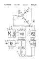
- FIG. 1 illustrates the controlled drive system for the phase windings of a three phase brushless direct current motor
- FIG. 2 illustrates one of three separate circuits which restore the phase to phase back electromotive force voltage of the three phase brushless direct current motor
- FIG. 3 illustrates one of two motor phase current source circuits that operate with the circuit of FIG. 2;
- FIG. 4 illustrates the phase to phase signals produced by all circuits associated with the phase windings
- FIG. 5 illustrates zero crossing comparator circuitry which further processes the phase to phase signals produced by the circuits associated with the phase windings
- FIG. 6 illustrates the signal processing by the circuitry of FIG. 5.
- a schematic representation of a brushless direct current motor 10 is seen to include phase windings 12, 14 and 16 each having an inductance value L associated therewith.
- the impedance of each phase winding also includes a resistance component having a resistance value of R.
- Each phase winding 12, 14 and 16 will experience a back emf voltage denoted as e 1 , e 2 , or e 3 in the energized phase windings produced by the rotation of a permanent magnetic rotor (not shown).
- the energization of the phase windings is accomplished by timed application of the phase voltages V 1 , V 2 , V 3 causing phase currents I 1 , I 2 , I 3 to flow in the respective phase windings.
- phase voltages V 1 , V 2 , and V 3 as well as the phase currents I 1 , I 2 , and I 3 are applied to a phase to phase back emf restoring circuit 24.
- the restoring circuit is operative to produce gain adjusted phase to phase back emf voltages e 1 -e 2 , e 2 -e 3 , and e 3 -e 1 .
- These signals are further processed by gated zero crossing comparator circuitry 26 which compares the phase to phase back emf voltage levels to ground just prior to zero crossover.
- Logic level signals equivalent to that obtained from Hall effect sensing devices are generated by the gated zero crossing comparator circuitry 26.
- commutation logic 27 which produces commutation logic level signals q 1 , q 2 , q 3 , q 4 , q 5 , and q 6 .
- the commutation logic level signals q 1 through q 6 are applied to a modulator 28 which also receives a current loop error signal from current control loop 29. It is to be appreciated that the commutation logic 27, the modulator 28 and the current control loop 29 are well known in the art.
- This circuitry is operative to produce the switching signals Q 1 through Q 6 which are applied to a three phase bridge driver circuit 30.
- the bridge driver circuit in combination with a power supply source 32 selectively applies the voltages V 1 , V 2 , and V 3 to the phase windings 12, 14 and 16. The selective application is dictated by power semiconductor switches responsive to the switching signals Q 1 through Q 6 in a manner well known in the art.
- the power supply associated with the three phase bridge driver is preferably a resonant link bus providing a fifty kilohertz signal of 450 peak volts sustainable for twenty microseconds. It is to be appreciated that the invention is equally applicable to a driver using a direct current bus and pulse width modulation (PWM) control.
- PWM pulse width modulation
- Top switches in the three phase bridge drive circuit 30 connect the resonant link bus 32 to the respective phase windings of the motor 10. Bottom switches associated with each winding connect respective windings back to the resonant link return bus 32.
- the modulator 28 produces the top switch signals Q 1 , Q 2 , and Q 3 for the respective top switches directly from the commutation logic level signals q 1 , q 2 and q 3 .
- the commutation logic 27 in combination with the modulator 28 and the current control loop 29 produces the signals Q 4 , Q 5 , and Q 6 for the bottom switches.
- the drive signal to the three bottom switches is modulated by the current control loop error signal in order to maintain a defined current in the brushless dc motor phase windings.
- Logic level changes in the q 1 through q 6 signals occur at the zero crossover points of phase to phase back emf voltages generated by the phase to phase back emf voltage restoring circuit which will be hereinafter described in detail.
- the circuit 34 produces an output voltage equivalent to the difference between the back emf voltages e 1 and e 2 . It is to be understood that there are two additional circuits not shown which produce output voltages equivalent to e 2 -e 3 and e 3 -e 1 .
- the circuit 34 includes resistors 36, 38, 40, and 42 which preferably perform a fifty to one voltage attenuation of the voltages V 1 and V 2 .
- the voltages V 1 and V 2 are the high voltage levels from the resonant link bus applied to the windings 12 and 14 respectively.
- the resulting attenuated voltages are furthermore each adjusted by RC configurations comprising capacitor 44 and resistor 46 for voltage V 1 and capacitor 48 and resistor 50 for voltage V 2 .
- the current drawn through each RC configuration is governed by a respective current source circuit.
- An example of a current source circuit is shown in FIG. 3.
- an LEM current sensor 52 develops a signal voltage across a resistor 54 which is proportional to the measured phase current, I 1 .
- This signal voltage is applied through a resistance 56 to an operational amplifier 58 having feed back resistance 60.
- the resulting inverted phase current signal, -I 1 preferably generates a voltage based on a ratio of amps of the current, I 1 , per volt to be experienced by the corresponding RC configuration of capacitor 44 and resistor 46.
- the current signal produced by the circuitry of FIG. 3 could be done by alternative circuitry not necessarily using a LEM sensor.
- a similar current source circuit produces a similar current effect of five amperes per volt for the current I 2 .
- This inverted current signal, -I 2 is experienced by the RC configuration comprising the capacitor 48 and resistor 50.
- each current source circuit works with its respective RC configuration in the circuit 34 to cancel or subtract out the signal component of the corresponding attenuated voltage of either V 1 or V 2 caused by the inductance and resistance of the phase winding for the particular V 1 or V 2 voltage.
- the thus adjusted voltages downstream of the respective RC configurations are applied to a differential amplifier 62 in FIG. 2 having the feed back resistance 42 and the ground reference resistance 38.
- the output of the differential amplifier configuration will be equivalent to the phase to phase difference in the back emf voltages e 1 and e 2 in the brushless d.c. motor 10 with the exception of a fifty kilohertz noise component and a noise spike coincident with communication switching.
- Both of these noise components are minimal with ideal cancellation (null balance) of the signal components in V 1 and V 2 caused by the inductance and resistance of the respective phase winding. They increase in amplitude with deviation from null balance which is caused by changes in motor phase winding parameters.
- a two pole RC low pass filter 64 having a band pass of two kilohertz attenuates these noise components. These components are further filtered out by the zero crossing comparator circuitry of FIG. 5 in a manner which will be addressed hereinafter.
- the output of the differential amplifier 62 will be equivalent to the phase to phase difference in the back emf voltages e 1 and e 2 .
- This is accomplished by configuring the circuits of FIGS. 2 and 3 in a manner which will now be described.
- current source circuits such as the circuit of FIG. 3 produce a given ratio of voltage to be experienced by an associated RC configuration per amperes of current in the phase windings. This ratio is preferably five amperes of phase winding current per volt to be experienced by an RC configuration. This given ratio allows the values of capacitance and resistance for each RC configuration in FIG. 2 to be accurately calculated as will now be described. Referring to FIG.
- the capacitors 44 and 48 are to have a capacitance value of "C” and the resistors 46 and 50 are to have resistance values of R 3 .
- the input resistors 36 and 40 are to have resistance values of R 1 and the resistors 38 and 42 are to have resistance values of R 2 .
- the following equation can be derived for the output voltage, V o , of the differential amplifier 62 in FIG. 2: ##EQU1##
- the following equation can also be written for the difference between the voltages V 1 and V 2 as a function of currents I 1 , I 2 and the phase winding inductances L and resistances R in the schematic representation of the brushless d.c. motor 10 of FIG. 1: ##EQU2##
- circuit 34 of FIG. 2 can be precisely configured to produce the phase to phase emf signal for e 1 -e 2 .
- phase to phase back emf signals of e 2 -e 3 and e 3 -e 1 .
- These circuits are all within the overall phase to phase back emf restoring circuit 24.
- the resulting periodic signals are illustrated in FIG. 4. It is to be noted that these signals have several undesirable spikes attributable to commutation switching. These signals are applied to the gated zero crossing comparator circuitry 26 which detects the zero crossing points of each signal having the undesirable spikes.
- the gated zero crossing comparator circuitry 26 is illustrated in detail.
- This circuitry is seen to include a bank of gated comparative amplifiers 66, 68, and 70 having feedback loops which are selectively disabled by gating logic 72 in association with switching configurations 74, 76, and 78.
- the feedback loop of each operational amplifier is disabled prior to the zero cross over of the respective phase to phase back emf signal applied to the amplifier and again enabled after crossover.
- Disablement of the feedback loop for the comparative amplifier 66 occurs when the switch in the switching configuration 74 is opened. This produces a zero voltage condition at the positive input of this comparative amplifier 66.
- Enablement of the feedback loop occurs when the switch in the switching configuration is closed.
- the resistance in the feedback loop attenuates the plus or minus output of the amplifier 66 so as to produce plus or minus ten volts at its plus input. These voltage levels are greater than the e 3 -e 1 signal level and hence prevent a change in the comparative decision.
- phase to phase back emf signal of e 3 -e 1 that is to be sampled for zero crossover is illustrated.
- This signal includes the undesirable spikes which are attributable to commutation switching.
- the gating signal for the switching configuration 74 associated with the operational amplifier 66 is also illustrated in FIG. 6.
- the gating logic signal produces gating pulses P 1 , P 2 , P 3 , and P 4 immediately prior to zero crossover of the phase to phase back emf signal.
- the pulse width is preferably sixty degrees minus a five hundred microsecond period of time.
- the operational amplifier 66 receives a comparator reference input signal as shown in FIG.
- Zero crossover decisions from the amplifiers 66, 68 and 70 also preferably trigger a multivibrator within the gating logic which develops logic pulses of five hundred microseconds. These latter pulses are used to shorten the period of each sixty degree pulse at its start.
- the resulting gating logic pulses such as P 1 , P 2 , P 3 , and P 4 for the feedback circuit 74 are generated on the output line 80 in FIG. 5. Similar gating logic pulses would be produced on output lines 82 and 84 for the feedback circuits 76 and 78.
- the zero comparator signal out of comparative amplifier 66 is seen to have leading and trailing edges defining zero voltage crossover points of the phase to phase back emf signal e 3 -e 1 . It is to be noted that similar zero comparator signals are produced by the operational amplifiers 68 and 70 for the zero crossover points of the phase to phase back emf signals e 2 -e 3 and e 1 -e 2 . These signals are illustrated relative to the corresponding phase to phase back emf signals in FIG. 4.
- the zero comparator signals are applied to the commutation logic 27 which produces the switching logic signals q 1 through q 6
- the switching signals q 1 and q 4 are responsive to the zero comparator signal from the operational amplifier 66
- q 2 and q 5 are responsive to the zero comparator signal from the operational amplifier 70
- the switching signals q 3 and q 6 are responsive to the zero comparator signal from the operational amplifier 68.
- the commutation logic signals q 1 through q 6 are applied to modulator 28.
- the modulator 28 produces the top switching signals Q 1 , Q 2 and Q 3 directly from the signals q 1 , q 2 and q 3 .
- the commutation logic 27 in conjunction with the modulator 28 and current control loop 29 produces the bottom switching signals Q 4 , Q 5 and Q 6 .
- the logically high portions of these signals define when a corresponding switch in the three phase bridge driver 30 is "on” so as to allow drive voltage to be appropriately applied to a particular phase winding in the brushless direct current motor 10.
Landscapes
- Engineering & Computer Science (AREA)
- Power Engineering (AREA)
- Control Of Motors That Do Not Use Commutators (AREA)
Abstract
Description
Claims (14)
Priority Applications (1)
| Application Number | Priority Date | Filing Date | Title |
|---|---|---|---|
| US08/112,036 US5367234A (en) | 1993-08-26 | 1993-08-26 | Control system for sensorless brushless DC motor |
Applications Claiming Priority (1)
| Application Number | Priority Date | Filing Date | Title |
|---|---|---|---|
| US08/112,036 US5367234A (en) | 1993-08-26 | 1993-08-26 | Control system for sensorless brushless DC motor |
Publications (1)
| Publication Number | Publication Date |
|---|---|
| US5367234A true US5367234A (en) | 1994-11-22 |
Family
ID=22341790
Family Applications (1)
| Application Number | Title | Priority Date | Filing Date |
|---|---|---|---|
| US08/112,036 Expired - Fee Related US5367234A (en) | 1993-08-26 | 1993-08-26 | Control system for sensorless brushless DC motor |
Country Status (1)
| Country | Link |
|---|---|
| US (1) | US5367234A (en) |
Cited By (45)
| Publication number | Priority date | Publication date | Assignee | Title |
|---|---|---|---|---|
| US5541484A (en) * | 1995-02-07 | 1996-07-30 | Carrier Corporation | BLDCM phase current reconstruction circuit |
| EP0736961A1 (en) * | 1995-04-07 | 1996-10-09 | Magneti Marelli France | Angular control device for a stepping motor |
| US5565753A (en) * | 1994-04-12 | 1996-10-15 | Allen-Bradley Company, Inc. | Method and apparatus for current rebalance in induction motor |
| US5627447A (en) * | 1995-09-29 | 1997-05-06 | Allen-Bradley Company, Inc. | Method and apparatus for detecting current delay angle from motor terminal voltage |
| US5646491A (en) * | 1995-05-11 | 1997-07-08 | General Electric Company | Electrical motor with a differential phase back EMF sensing circuit for sensing rotor position |
| US5675464A (en) * | 1996-05-02 | 1997-10-07 | Siemens Electric Limited | Stall or reduced-speed protection system for electric motor |
| US5691856A (en) * | 1995-10-10 | 1997-11-25 | Quantum Corporation | Apparatus and method for providing selective hysteresis for zero crossings of a disk drive spindle motor |
| EP0822649A1 (en) * | 1996-08-01 | 1998-02-04 | STMicroelectronics S.r.l. | Reconstruction of BEMF signals for synchronizing the driving of brushless-sensorless motors by means of redefine driving signals |
| FR2753319A1 (en) * | 1996-09-10 | 1998-03-13 | Soc D Mecanique Magnetique | ANGULAR POSITION DETECTION DEVICE FOR DRIVING A PERMANENT MAGNET-DRIVEN SYNCHRONOUS MOTOR |
| US5744921A (en) | 1996-05-02 | 1998-04-28 | Siemens Electric Limited | Control circuit for five-phase brushless DC motor |
| US5780983A (en) * | 1994-03-15 | 1998-07-14 | Seiko Epson Corporation | Brushless DC motor drive apparatus |
| US5802248A (en) * | 1996-01-02 | 1998-09-01 | Tannas Co. | Multi-speed motor |
| US5835992A (en) * | 1995-12-28 | 1998-11-10 | Samsung Electronics Co., Ltd. | Switching control signal generator for small precision motor |
| US5859512A (en) * | 1996-01-24 | 1999-01-12 | U.S. Philips Corporation | Drive circuit supplying drive signals to a plurality of windings of a multi-phase d.c. motor |
| US5869944A (en) * | 1995-02-16 | 1999-02-09 | Sony Corporation | Motor driving apparatus |
| US5923134A (en) * | 1996-12-10 | 1999-07-13 | Zexel Corporation | Method and device for driving DC brushless motor |
| US6089115A (en) * | 1998-08-19 | 2000-07-18 | Dana Corporation | Angular transmission using magnetorheological fluid (MR fluid) |
| US6163120A (en) * | 1996-12-17 | 2000-12-19 | Stmicroelectronics, Inc. | Simple back emf reconstruction in pulse width modulation (PWM) mode |
| US6215261B1 (en) | 1999-05-21 | 2001-04-10 | General Electric Company | Application specific integrated circuit for controlling power devices for commutating a motor based on the back emf of motor |
| US6310450B1 (en) * | 1999-04-23 | 2001-10-30 | Stmicroelectronics S.R.L. | Drive system of a brushless motor equipped with hall sensors self-discriminating the actual phasing of the installed sensors |
| US6316895B1 (en) * | 1999-09-01 | 2001-11-13 | Ramachandran Ramarathnam | Multi-speed motor controller |
| US6433497B1 (en) * | 1999-05-20 | 2002-08-13 | Fairchild Korea Semiconductor Ltd. | Drive circuit of a three phase BLDC motor |
| US6462495B1 (en) | 2000-04-25 | 2002-10-08 | Infineon Technologies Ag | Controlling a brushless DC motor |
| US20020171388A1 (en) * | 2001-05-18 | 2002-11-21 | Kunio Seki | Apparatus for driving three-phase half-wave drive brushless motor |
| US6534938B1 (en) * | 2001-09-28 | 2003-03-18 | Delta Electronics Inc. | Method and apparatus for driving a sensorless BLDC motor at PWM operation mode |
| US6633145B2 (en) * | 2001-11-20 | 2003-10-14 | Stmicroelectronics, Inc. | Circuit for improved back EMF detection |
| US6686714B2 (en) | 2002-06-21 | 2004-02-03 | International Business Machines Corporation | Method and system for improved closed loop control of sensorless brushless DC motors |
| US20040070356A1 (en) * | 2002-06-13 | 2004-04-15 | Halliburton Energy Services, Inc. | Digital adaptive sensorless commutational drive controller for a brushless DC motor |
| US6759827B2 (en) * | 2000-09-18 | 2004-07-06 | Boc Edwards Japan Limited | Control circuit of brush-less motor, control circuit of sensor-less brush-less motor, brush-less motor apparatus, sensor-less brush-less motor apparatus and vacuum pump apparatus |
| FR2851093A1 (en) * | 2003-02-06 | 2004-08-13 | Toyota Motor Co Ltd | ROTATION CONTROL SYSTEM FOR MOTOR |
| WO2005025050A1 (en) * | 2003-09-05 | 2005-03-17 | Matsushita Electric Industrial Co., Ltd. | Driving method and driving apparatus of permanent magnet synchronous motor for extending flux weakening region |
| US20050104545A1 (en) * | 2003-11-05 | 2005-05-19 | Atsushi Kikuchi | Sensorless brushless motor |
| US20050212472A1 (en) * | 2004-03-24 | 2005-09-29 | Chapman Danny K | Method and apparatus for time-based dc motor commutation |
| US20060152181A1 (en) * | 2005-01-07 | 2006-07-13 | Stmicroelectronics, Inc. | Back EMF detection circuit and method for a sensorless brushless DC (BLDC) motor |
| US20070216325A1 (en) * | 2006-03-15 | 2007-09-20 | Matsushita Electric Industrial Co., Ltd. | Motor drive device and motor drive method |
| US20090058330A1 (en) * | 2007-08-30 | 2009-03-05 | Seagate Technology Llc | Driving a multi-phased motor |
| US20090278485A1 (en) * | 2005-12-15 | 2009-11-12 | Rolf Strothmann | Device and Method for Determining the Rotational Position of a Rotor in an Electric Machine |
| CN102055392A (en) * | 2010-12-17 | 2011-05-11 | 北京控制工程研究所 | Sensorless line back electromotive force (EMF) position detection method of brushless direct current motor (BLDCM) |
| CN101499761B (en) * | 2008-02-01 | 2011-11-09 | 远翔科技股份有限公司 | Control device and method for starting brushless DC motor |
| US20130015794A1 (en) * | 2011-07-13 | 2013-01-17 | Texas Instruments Incorporated | Closed loop startup control for a sensorless, brushless dc motor |
| US8836747B2 (en) | 2012-10-02 | 2014-09-16 | Lexmark International, Inc. | Motor control system and method for a laser scanning unit of an imaging apparatus |
| US20160173014A1 (en) * | 2014-12-15 | 2016-06-16 | Stmicroelectronics S.R.L. | Method of driving brushless motors, corresponding device, motor and computer program product |
| WO2016128028A1 (en) * | 2015-02-10 | 2016-08-18 | Pierburg Pump Technology Gmbh | Electric motor vehicle auxiliary unit and method for commutating a motor vehicle auxiliary unit |
| US9523947B2 (en) | 2012-09-26 | 2016-12-20 | Lexmark International, Inc. | Time-based commutation method and system for controlling a fuser assembly |
| CN106992725A (en) * | 2016-01-20 | 2017-07-28 | 珠海格力节能环保制冷技术研究中心有限公司 | The position detecting circuit and method of motor |
Citations (19)
| Publication number | Priority date | Publication date | Assignee | Title |
|---|---|---|---|---|
| US4136308A (en) * | 1977-08-29 | 1979-01-23 | King Kenyon M | Stepping motor control |
| US4262236A (en) * | 1979-04-11 | 1981-04-14 | General Motors Corporation | Commutatorless direct current motor drive system |
| US4262237A (en) * | 1979-06-08 | 1981-04-14 | General Motors Corporation | Commutatorless direct current motor drive system |
| US4446406A (en) * | 1982-04-02 | 1984-05-01 | Sony Corporation | Brushless DC motor driving circuit |
| US4459519A (en) * | 1974-06-24 | 1984-07-10 | General Electric Company | Electronically commutated motor systems and control therefor |
| US4491772A (en) * | 1983-06-09 | 1985-01-01 | General Electric Company | Control circuit for an electronically commutated motor (ECM), method of timing the electronic commutation of an ECM, and method of operating an ECM |
| US4494054A (en) * | 1983-04-13 | 1985-01-15 | Pellegrini Gerald N | Electric power delivery system and method |
| US4651069A (en) * | 1983-04-13 | 1987-03-17 | Pellegrini Gerald N | Back-emf brushless d.c. motor drive circuit |
| US4651067A (en) * | 1984-02-24 | 1987-03-17 | Hitachi, Ltd. | Apparatus for driving brushless motor |
| US4678973A (en) * | 1986-10-07 | 1987-07-07 | General Motors Corporation | Sensorless starting control for a brushless DC motor |
| US4694210A (en) * | 1986-07-31 | 1987-09-15 | General Motors Corporation | Brushless DC motor and sensorless drive arrangement therefor |
| US4743815A (en) * | 1987-09-01 | 1988-05-10 | Emerson Electric Co. | Brushless permanent magnet motor system |
| US4857814A (en) * | 1985-09-16 | 1989-08-15 | Fisher & Paykel | Electronic motor controls, laundry machines including such controls and/or methods of operating such controls |
| US4928043A (en) * | 1988-11-14 | 1990-05-22 | Synektron Corporation | Back EMF sampling circuit for phase locked loop motor control |
| US4970445A (en) * | 1987-09-04 | 1990-11-13 | Matsushita Electric Industrial Co., Ltd. | Brushless motor drive device |
| US5187419A (en) * | 1991-05-06 | 1993-02-16 | Allen-Bradley Company, Inc. | Electric motor control apparatus and method |
| US5202614A (en) * | 1989-09-25 | 1993-04-13 | Silicon Systems, Inc. | Self-commutating, back-emf sensing, brushless dc motor controller |
| US5221881A (en) * | 1991-10-03 | 1993-06-22 | Sgs-Thomson Microelectronics, Inc. | Method and apparatus for operating polyphase DC motors |
| US5245256A (en) * | 1991-02-15 | 1993-09-14 | Seagate Technology, Inc. | Closed loop control of a brushless DC motor at nominal speed |
-
1993
- 1993-08-26 US US08/112,036 patent/US5367234A/en not_active Expired - Fee Related
Patent Citations (19)
| Publication number | Priority date | Publication date | Assignee | Title |
|---|---|---|---|---|
| US4459519A (en) * | 1974-06-24 | 1984-07-10 | General Electric Company | Electronically commutated motor systems and control therefor |
| US4136308A (en) * | 1977-08-29 | 1979-01-23 | King Kenyon M | Stepping motor control |
| US4262236A (en) * | 1979-04-11 | 1981-04-14 | General Motors Corporation | Commutatorless direct current motor drive system |
| US4262237A (en) * | 1979-06-08 | 1981-04-14 | General Motors Corporation | Commutatorless direct current motor drive system |
| US4446406A (en) * | 1982-04-02 | 1984-05-01 | Sony Corporation | Brushless DC motor driving circuit |
| US4494054A (en) * | 1983-04-13 | 1985-01-15 | Pellegrini Gerald N | Electric power delivery system and method |
| US4651069A (en) * | 1983-04-13 | 1987-03-17 | Pellegrini Gerald N | Back-emf brushless d.c. motor drive circuit |
| US4491772A (en) * | 1983-06-09 | 1985-01-01 | General Electric Company | Control circuit for an electronically commutated motor (ECM), method of timing the electronic commutation of an ECM, and method of operating an ECM |
| US4651067A (en) * | 1984-02-24 | 1987-03-17 | Hitachi, Ltd. | Apparatus for driving brushless motor |
| US4857814A (en) * | 1985-09-16 | 1989-08-15 | Fisher & Paykel | Electronic motor controls, laundry machines including such controls and/or methods of operating such controls |
| US4694210A (en) * | 1986-07-31 | 1987-09-15 | General Motors Corporation | Brushless DC motor and sensorless drive arrangement therefor |
| US4678973A (en) * | 1986-10-07 | 1987-07-07 | General Motors Corporation | Sensorless starting control for a brushless DC motor |
| US4743815A (en) * | 1987-09-01 | 1988-05-10 | Emerson Electric Co. | Brushless permanent magnet motor system |
| US4970445A (en) * | 1987-09-04 | 1990-11-13 | Matsushita Electric Industrial Co., Ltd. | Brushless motor drive device |
| US4928043A (en) * | 1988-11-14 | 1990-05-22 | Synektron Corporation | Back EMF sampling circuit for phase locked loop motor control |
| US5202614A (en) * | 1989-09-25 | 1993-04-13 | Silicon Systems, Inc. | Self-commutating, back-emf sensing, brushless dc motor controller |
| US5245256A (en) * | 1991-02-15 | 1993-09-14 | Seagate Technology, Inc. | Closed loop control of a brushless DC motor at nominal speed |
| US5187419A (en) * | 1991-05-06 | 1993-02-16 | Allen-Bradley Company, Inc. | Electric motor control apparatus and method |
| US5221881A (en) * | 1991-10-03 | 1993-06-22 | Sgs-Thomson Microelectronics, Inc. | Method and apparatus for operating polyphase DC motors |
Non-Patent Citations (6)
| Title |
|---|
| B. C. Kuo & K. Butts, "Closed-Loop Control of a 3.6° Floppy-Disk Drive PM Motor by Back-EMF Sensing", Proceedings, Eleventh Annual Symposium on Incremental Motion Control Systems and Devices, May, 1982. |
| B. C. Kuo & K. Butts, Closed Loop Control of a 3.6 Floppy Disk Drive PM Motor by Back EMF Sensing , Proceedings, Eleventh Annual Symposium on Incremental Motion Control Systems and Devices, May, 1982. * |
| SRL Inc. Quarterly Report, "Research on the PDM 253/25 Step Motor" Mar., 1980. |
| SRL Inc. Quarterly Report, Research on the PDM 253/25 Step Motor Mar., 1980. * |
| W. C. Lin, B. C. Kuo & U. Goerke, "Waveform Detection of Permanent-Magnet Step Motors", Parts I & II, Proceedings of Eighth Annual Symposium on IMCSD Mar. 1979, pp. 227-256. |
| W. C. Lin, B. C. Kuo & U. Goerke, Waveform Detection of Permanent Magnet Step Motors , Parts I & II, Proceedings of Eighth Annual Symposium on IMCSD Mar. 1979, pp. 227 256. * |
Cited By (67)
| Publication number | Priority date | Publication date | Assignee | Title |
|---|---|---|---|---|
| US5780983A (en) * | 1994-03-15 | 1998-07-14 | Seiko Epson Corporation | Brushless DC motor drive apparatus |
| US5565753A (en) * | 1994-04-12 | 1996-10-15 | Allen-Bradley Company, Inc. | Method and apparatus for current rebalance in induction motor |
| US5541484A (en) * | 1995-02-07 | 1996-07-30 | Carrier Corporation | BLDCM phase current reconstruction circuit |
| EP0730341A3 (en) * | 1995-02-16 | 2000-08-02 | Sony Corporation | Motor driving apparatus |
| US5869944A (en) * | 1995-02-16 | 1999-02-09 | Sony Corporation | Motor driving apparatus |
| FR2732834A1 (en) * | 1995-04-07 | 1996-10-11 | Magneti Marelli France | ANGULAR CONTROL DEVICE OF A STEPPER MOTOR |
| EP0736961A1 (en) * | 1995-04-07 | 1996-10-09 | Magneti Marelli France | Angular control device for a stepping motor |
| US5646491A (en) * | 1995-05-11 | 1997-07-08 | General Electric Company | Electrical motor with a differential phase back EMF sensing circuit for sensing rotor position |
| US5627447A (en) * | 1995-09-29 | 1997-05-06 | Allen-Bradley Company, Inc. | Method and apparatus for detecting current delay angle from motor terminal voltage |
| US5691856A (en) * | 1995-10-10 | 1997-11-25 | Quantum Corporation | Apparatus and method for providing selective hysteresis for zero crossings of a disk drive spindle motor |
| US5835992A (en) * | 1995-12-28 | 1998-11-10 | Samsung Electronics Co., Ltd. | Switching control signal generator for small precision motor |
| US5802248A (en) * | 1996-01-02 | 1998-09-01 | Tannas Co. | Multi-speed motor |
| US5859512A (en) * | 1996-01-24 | 1999-01-12 | U.S. Philips Corporation | Drive circuit supplying drive signals to a plurality of windings of a multi-phase d.c. motor |
| US5675464A (en) * | 1996-05-02 | 1997-10-07 | Siemens Electric Limited | Stall or reduced-speed protection system for electric motor |
| US5744921A (en) | 1996-05-02 | 1998-04-28 | Siemens Electric Limited | Control circuit for five-phase brushless DC motor |
| EP0822649A1 (en) * | 1996-08-01 | 1998-02-04 | STMicroelectronics S.r.l. | Reconstruction of BEMF signals for synchronizing the driving of brushless-sensorless motors by means of redefine driving signals |
| US5838128A (en) * | 1996-08-01 | 1998-11-17 | Sgs-Thomson Microelectronics S.R.I. | Reconstruction of BEMF signals for synchronizing the driving of brushless- sensorless motors by means of predefined driving signals |
| US6236183B1 (en) | 1996-09-10 | 2001-05-22 | Societe De Mecanique Magnetique | Device for sensing the angular position for controlling a synchronous motor excited by a permanent magnet |
| WO1998011662A1 (en) * | 1996-09-10 | 1998-03-19 | Societe De Mecanique Magnetique | Device for sensing the angular position for controlling a synchronous motor excited by a permanent magnet |
| FR2753319A1 (en) * | 1996-09-10 | 1998-03-13 | Soc D Mecanique Magnetique | ANGULAR POSITION DETECTION DEVICE FOR DRIVING A PERMANENT MAGNET-DRIVEN SYNCHRONOUS MOTOR |
| US5923134A (en) * | 1996-12-10 | 1999-07-13 | Zexel Corporation | Method and device for driving DC brushless motor |
| US6163120A (en) * | 1996-12-17 | 2000-12-19 | Stmicroelectronics, Inc. | Simple back emf reconstruction in pulse width modulation (PWM) mode |
| US6089115A (en) * | 1998-08-19 | 2000-07-18 | Dana Corporation | Angular transmission using magnetorheological fluid (MR fluid) |
| US6310450B1 (en) * | 1999-04-23 | 2001-10-30 | Stmicroelectronics S.R.L. | Drive system of a brushless motor equipped with hall sensors self-discriminating the actual phasing of the installed sensors |
| US6433497B1 (en) * | 1999-05-20 | 2002-08-13 | Fairchild Korea Semiconductor Ltd. | Drive circuit of a three phase BLDC motor |
| US6215261B1 (en) | 1999-05-21 | 2001-04-10 | General Electric Company | Application specific integrated circuit for controlling power devices for commutating a motor based on the back emf of motor |
| US6316895B1 (en) * | 1999-09-01 | 2001-11-13 | Ramachandran Ramarathnam | Multi-speed motor controller |
| US6462495B1 (en) | 2000-04-25 | 2002-10-08 | Infineon Technologies Ag | Controlling a brushless DC motor |
| US6661192B2 (en) | 2000-04-25 | 2003-12-09 | Infineon Technologies Ag | Controlling a brushless DC motor |
| US6759827B2 (en) * | 2000-09-18 | 2004-07-06 | Boc Edwards Japan Limited | Control circuit of brush-less motor, control circuit of sensor-less brush-less motor, brush-less motor apparatus, sensor-less brush-less motor apparatus and vacuum pump apparatus |
| US20020171388A1 (en) * | 2001-05-18 | 2002-11-21 | Kunio Seki | Apparatus for driving three-phase half-wave drive brushless motor |
| US6534938B1 (en) * | 2001-09-28 | 2003-03-18 | Delta Electronics Inc. | Method and apparatus for driving a sensorless BLDC motor at PWM operation mode |
| US6633145B2 (en) * | 2001-11-20 | 2003-10-14 | Stmicroelectronics, Inc. | Circuit for improved back EMF detection |
| US20040070356A1 (en) * | 2002-06-13 | 2004-04-15 | Halliburton Energy Services, Inc. | Digital adaptive sensorless commutational drive controller for a brushless DC motor |
| US7030582B2 (en) | 2002-06-13 | 2006-04-18 | Halliburton Energy Services, Inc. | Digital adaptive sensorless commutational drive controller for a brushless DC motor |
| US20040131342A1 (en) * | 2002-06-13 | 2004-07-08 | Halliburton Energy Services, Inc. | Digital adaptive sensorless commutational drive controller for a brushless DC motor |
| US6901212B2 (en) | 2002-06-13 | 2005-05-31 | Halliburton Energy Services, Inc. | Digital adaptive sensorless commutational drive controller for a brushless DC motor |
| US7239098B2 (en) | 2002-06-13 | 2007-07-03 | Halliburton Energy Services, Inc. | Digital adaptive sensorless commutational drive controller for a brushless DC motor |
| US6686714B2 (en) | 2002-06-21 | 2004-02-03 | International Business Machines Corporation | Method and system for improved closed loop control of sensorless brushless DC motors |
| FR2851093A1 (en) * | 2003-02-06 | 2004-08-13 | Toyota Motor Co Ltd | ROTATION CONTROL SYSTEM FOR MOTOR |
| WO2005025050A1 (en) * | 2003-09-05 | 2005-03-17 | Matsushita Electric Industrial Co., Ltd. | Driving method and driving apparatus of permanent magnet synchronous motor for extending flux weakening region |
| US7122985B2 (en) * | 2003-11-05 | 2006-10-17 | Sony Corporation | Sensorless brushless motor |
| US20050104545A1 (en) * | 2003-11-05 | 2005-05-19 | Atsushi Kikuchi | Sensorless brushless motor |
| US7205738B2 (en) | 2004-03-24 | 2007-04-17 | Lexmark International, Inc. | Method and apparatus for time-based dc motor commutation |
| US20050212472A1 (en) * | 2004-03-24 | 2005-09-29 | Chapman Danny K | Method and apparatus for time-based dc motor commutation |
| US20060152181A1 (en) * | 2005-01-07 | 2006-07-13 | Stmicroelectronics, Inc. | Back EMF detection circuit and method for a sensorless brushless DC (BLDC) motor |
| US7301298B2 (en) * | 2005-01-07 | 2007-11-27 | Stmicroelectronics, Inc. | Back EMF detection circuit and method for a sensorless brushless DC (BLDC) motor |
| US20090278485A1 (en) * | 2005-12-15 | 2009-11-12 | Rolf Strothmann | Device and Method for Determining the Rotational Position of a Rotor in an Electric Machine |
| US8222847B2 (en) * | 2005-12-15 | 2012-07-17 | Rolf Strothmann | Device and method for determining the rotational position of a rotor in an electric machine |
| US7768226B2 (en) * | 2006-03-15 | 2010-08-03 | Panasonic Corporation | Motor drive device and motor drive method |
| US20070216325A1 (en) * | 2006-03-15 | 2007-09-20 | Matsushita Electric Industrial Co., Ltd. | Motor drive device and motor drive method |
| US20090058330A1 (en) * | 2007-08-30 | 2009-03-05 | Seagate Technology Llc | Driving a multi-phased motor |
| CN101499761B (en) * | 2008-02-01 | 2011-11-09 | 远翔科技股份有限公司 | Control device and method for starting brushless DC motor |
| CN102055392A (en) * | 2010-12-17 | 2011-05-11 | 北京控制工程研究所 | Sensorless line back electromotive force (EMF) position detection method of brushless direct current motor (BLDCM) |
| CN102055392B (en) * | 2010-12-17 | 2015-11-25 | 北京控制工程研究所 | A kind of brshless DC motor is without pickup wire back-emf method for detecting position |
| US20130015794A1 (en) * | 2011-07-13 | 2013-01-17 | Texas Instruments Incorporated | Closed loop startup control for a sensorless, brushless dc motor |
| US8933657B2 (en) * | 2011-07-13 | 2015-01-13 | Texas Instruments Incorporated | Closed loop startup control for a sensorless, brushless DC motor |
| US9523947B2 (en) | 2012-09-26 | 2016-12-20 | Lexmark International, Inc. | Time-based commutation method and system for controlling a fuser assembly |
| US8836747B2 (en) | 2012-10-02 | 2014-09-16 | Lexmark International, Inc. | Motor control system and method for a laser scanning unit of an imaging apparatus |
| US20160173014A1 (en) * | 2014-12-15 | 2016-06-16 | Stmicroelectronics S.R.L. | Method of driving brushless motors, corresponding device, motor and computer program product |
| US9768717B2 (en) * | 2014-12-15 | 2017-09-19 | Stmicroelectronics S.R.L. | Method of driving brushless motors, corresponding device, motor and computer program product |
| WO2016128028A1 (en) * | 2015-02-10 | 2016-08-18 | Pierburg Pump Technology Gmbh | Electric motor vehicle auxiliary unit and method for commutating a motor vehicle auxiliary unit |
| CN107210692A (en) * | 2015-02-10 | 2017-09-26 | 皮尔伯格泵技术有限责任公司 | Electric automobile aids in unit and the method for aiding in unit to be commutated in automobile |
| US10193474B2 (en) | 2015-02-10 | 2019-01-29 | Pierburg Pump Technology Gmbh | Electric motor vehicle auxiliary unit and method for commutating a motor vehicle auxiliary unit |
| CN107210692B (en) * | 2015-02-10 | 2020-04-07 | 皮尔伯格泵技术有限责任公司 | Electric vehicle auxiliary unit and method for reversing vehicle auxiliary unit |
| CN106992725A (en) * | 2016-01-20 | 2017-07-28 | 珠海格力节能环保制冷技术研究中心有限公司 | The position detecting circuit and method of motor |
| CN106992725B (en) * | 2016-01-20 | 2024-01-12 | 珠海格力节能环保制冷技术研究中心有限公司 | Position detection circuit and method for motor |
Similar Documents
| Publication | Publication Date | Title |
|---|---|---|
| US5367234A (en) | Control system for sensorless brushless DC motor | |
| US8018188B2 (en) | Method and device for determining the position of a rotor of a brushless and sensorless electric motor | |
| US4912378A (en) | Third harmonic commutation control system and method | |
| US5977737A (en) | Digital motor driver circuit and method | |
| US6061258A (en) | Monitoring of current in an inductive load, PWM driven through a bridge stage | |
| US5929577A (en) | Brushless DC motor controller | |
| US4074179A (en) | Position detection methods and apparatus for stepping motors | |
| EP1226061B1 (en) | Method and system of testing continuity for a motor and associated drive circuitry | |
| EP0295710B1 (en) | Driving apparatus for brush-less motor | |
| EP0123807B1 (en) | Driving and detection of back emf in permanent magnet step motors | |
| US4988939A (en) | Electric motor with variable commutation delay | |
| US6181092B1 (en) | Current control circuit for a reluctance machine | |
| US5923134A (en) | Method and device for driving DC brushless motor | |
| EP0822649B1 (en) | Reconstruction of BEMF signals for synchronizing the driving of brushless-sensorless motors by means of redefine driving signals | |
| US6288507B1 (en) | Motor drive circuit | |
| US5015927A (en) | Electric motor with regeneration current commutation | |
| US4827196A (en) | Motor control arrangement | |
| CA1209199A (en) | Device for controlling a reluctance motor | |
| US5656910A (en) | Driver circuit for a stepping motor | |
| US5503248A (en) | Maintaining open loop current drive to linear induction motor | |
| KR20070000444A (en) | Motor drive control circuit, and motor apparatus using the same | |
| US5761375A (en) | Brushless motor speed detection device | |
| US5602452A (en) | Regeneration current-spike limiter for six-step motor drives | |
| US4281242A (en) | Balancing apparatus for magnetic circuits employed in data storage and retrieval systems | |
| US7514891B2 (en) | Method and arrangement for monitoring a power output stage |
Legal Events
| Date | Code | Title | Description |
|---|---|---|---|
| AS | Assignment |
Owner name: CARRIER CORPORATION/STEPHEN REVIS, NEW YORK Free format text: ASSIGNMENT OF ASSIGNORS INTEREST;ASSIGNOR:DITUCCI, JOSEPH;REEL/FRAME:006751/0433 Effective date: 19930813 |
|
| AS | Assignment |
Owner name: GERALD N. PELLEGRINI, MASSACHUSETTS Free format text: ASSIGNMENT OF ASSIGNORS INTEREST;ASSIGNOR:CARRIER CORPORATION;REEL/FRAME:008478/0825 Effective date: 19960105 |
|
| FEPP | Fee payment procedure |
Free format text: PAT HOLDER CLAIMS SMALL ENTITY STATUS - SMALL BUSINESS (ORIGINAL EVENT CODE: SM02); ENTITY STATUS OF PATENT OWNER: SMALL ENTITY |
|
| REMI | Maintenance fee reminder mailed | ||
| LAPS | Lapse for failure to pay maintenance fees | ||
| FP | Lapsed due to failure to pay maintenance fee |
Effective date: 19981122 |
|
| STCH | Information on status: patent discontinuation |
Free format text: PATENT EXPIRED DUE TO NONPAYMENT OF MAINTENANCE FEES UNDER 37 CFR 1.362 |