US5363547A - Method for attaching rotors to crankshafts - Google Patents
Method for attaching rotors to crankshafts Download PDFInfo
- Publication number
- US5363547A US5363547A US08/121,632 US12163293A US5363547A US 5363547 A US5363547 A US 5363547A US 12163293 A US12163293 A US 12163293A US 5363547 A US5363547 A US 5363547A
- Authority
- US
- United States
- Prior art keywords
- rotor
- bore
- heating
- members
- crankshaft
- Prior art date
- Legal status (The legal status is an assumption and is not a legal conclusion. Google has not performed a legal analysis and makes no representation as to the accuracy of the status listed.)
- Expired - Lifetime
Links
- 238000000034 method Methods 0.000 title claims description 15
- 238000010438 heat treatment Methods 0.000 claims abstract description 23
- 230000006698 induction Effects 0.000 claims abstract description 14
- 230000005291 magnetic effect Effects 0.000 abstract description 10
- 230000010339 dilation Effects 0.000 abstract 1
- 230000005294 ferromagnetic effect Effects 0.000 description 5
- 238000003780 insertion Methods 0.000 description 4
- 230000037431 insertion Effects 0.000 description 4
- 230000002441 reversible effect Effects 0.000 description 4
- 239000000853 adhesive Substances 0.000 description 3
- 230000001070 adhesive effect Effects 0.000 description 3
- 238000003475 lamination Methods 0.000 description 3
- 230000035515 penetration Effects 0.000 description 3
- 239000003302 ferromagnetic material Substances 0.000 description 2
- 230000001939 inductive effect Effects 0.000 description 2
- 239000000696 magnetic material Substances 0.000 description 2
- 239000000463 material Substances 0.000 description 2
- 230000002093 peripheral effect Effects 0.000 description 2
- 230000008646 thermal stress Effects 0.000 description 2
- 229910052779 Neodymium Inorganic materials 0.000 description 1
- 238000004026 adhesive bonding Methods 0.000 description 1
- 229910000828 alnico Inorganic materials 0.000 description 1
- XAGFODPZIPBFFR-UHFFFAOYSA-N aluminium Chemical compound [Al] XAGFODPZIPBFFR-UHFFFAOYSA-N 0.000 description 1
- 229910052782 aluminium Inorganic materials 0.000 description 1
- 229910010293 ceramic material Inorganic materials 0.000 description 1
- 238000001816 cooling Methods 0.000 description 1
- 235000021438 curry Nutrition 0.000 description 1
- 230000006378 damage Effects 0.000 description 1
- 238000010586 diagram Methods 0.000 description 1
- 230000000694 effects Effects 0.000 description 1
- 238000009434 installation Methods 0.000 description 1
- QEFYFXOXNSNQGX-UHFFFAOYSA-N neodymium atom Chemical compound [Nd] QEFYFXOXNSNQGX-UHFFFAOYSA-N 0.000 description 1
- 230000010287 polarization Effects 0.000 description 1
- 230000001105 regulatory effect Effects 0.000 description 1
- 230000035939 shock Effects 0.000 description 1
- 229910001220 stainless steel Inorganic materials 0.000 description 1
- 239000010935 stainless steel Substances 0.000 description 1
- 229910000859 α-Fe Inorganic materials 0.000 description 1
Images

Classifications
-
- F—MECHANICAL ENGINEERING; LIGHTING; HEATING; WEAPONS; BLASTING
- F16—ENGINEERING ELEMENTS AND UNITS; GENERAL MEASURES FOR PRODUCING AND MAINTAINING EFFECTIVE FUNCTIONING OF MACHINES OR INSTALLATIONS; THERMAL INSULATION IN GENERAL
- F16B—DEVICES FOR FASTENING OR SECURING CONSTRUCTIONAL ELEMENTS OR MACHINE PARTS TOGETHER, e.g. NAILS, BOLTS, CIRCLIPS, CLAMPS, CLIPS OR WEDGES; JOINTS OR JOINTING
- F16B4/00—Shrinkage connections, e.g. assembled with the parts at different temperature; Force fits; Non-releasable friction-grip fastenings
- F16B4/006—Shrinkage connections, e.g. assembled with the parts being at different temperature
-
- H—ELECTRICITY
- H02—GENERATION; CONVERSION OR DISTRIBUTION OF ELECTRIC POWER
- H02K—DYNAMO-ELECTRIC MACHINES
- H02K15/00—Processes or apparatus specially adapted for manufacturing, assembling, maintaining or repairing of dynamo-electric machines
- H02K15/02—Processes or apparatus specially adapted for manufacturing, assembling, maintaining or repairing of dynamo-electric machines of stator or rotor bodies
- H02K15/028—Fastening stator or rotor bodies to casings, supports, shafts or hubs
-
- H—ELECTRICITY
- H02—GENERATION; CONVERSION OR DISTRIBUTION OF ELECTRIC POWER
- H02K—DYNAMO-ELECTRIC MACHINES
- H02K15/00—Processes or apparatus specially adapted for manufacturing, assembling, maintaining or repairing of dynamo-electric machines
- H02K15/02—Processes or apparatus specially adapted for manufacturing, assembling, maintaining or repairing of dynamo-electric machines of stator or rotor bodies
- H02K15/03—Processes or apparatus specially adapted for manufacturing, assembling, maintaining or repairing of dynamo-electric machines of stator or rotor bodies having permanent magnets
-
- Y—GENERAL TAGGING OF NEW TECHNOLOGICAL DEVELOPMENTS; GENERAL TAGGING OF CROSS-SECTIONAL TECHNOLOGIES SPANNING OVER SEVERAL SECTIONS OF THE IPC; TECHNICAL SUBJECTS COVERED BY FORMER USPC CROSS-REFERENCE ART COLLECTIONS [XRACs] AND DIGESTS
- Y10—TECHNICAL SUBJECTS COVERED BY FORMER USPC
- Y10T—TECHNICAL SUBJECTS COVERED BY FORMER US CLASSIFICATION
- Y10T29/00—Metal working
- Y10T29/49—Method of mechanical manufacture
- Y10T29/49002—Electrical device making
- Y10T29/49009—Dynamoelectric machine
- Y10T29/49012—Rotor
-
- Y—GENERAL TAGGING OF NEW TECHNOLOGICAL DEVELOPMENTS; GENERAL TAGGING OF CROSS-SECTIONAL TECHNOLOGIES SPANNING OVER SEVERAL SECTIONS OF THE IPC; TECHNICAL SUBJECTS COVERED BY FORMER USPC CROSS-REFERENCE ART COLLECTIONS [XRACs] AND DIGESTS
- Y10—TECHNICAL SUBJECTS COVERED BY FORMER USPC
- Y10T—TECHNICAL SUBJECTS COVERED BY FORMER US CLASSIFICATION
- Y10T29/00—Metal working
- Y10T29/53—Means to assemble or disassemble
- Y10T29/5313—Means to assemble electrical device
- Y10T29/53143—Motor or generator
-
- Y—GENERAL TAGGING OF NEW TECHNOLOGICAL DEVELOPMENTS; GENERAL TAGGING OF CROSS-SECTIONAL TECHNOLOGIES SPANNING OVER SEVERAL SECTIONS OF THE IPC; TECHNICAL SUBJECTS COVERED BY FORMER USPC CROSS-REFERENCE ART COLLECTIONS [XRACs] AND DIGESTS
- Y10—TECHNICAL SUBJECTS COVERED BY FORMER USPC
- Y10T—TECHNICAL SUBJECTS COVERED BY FORMER US CLASSIFICATION
- Y10T29/00—Metal working
- Y10T29/53—Means to assemble or disassemble
- Y10T29/53439—Means to assemble or disassemble including provision to utilize thermal expansion of work
Definitions
- an electronically commutated motor includes a permanent magnet rotor assembly.
- the rotor assembly has a low reluctance core formed as an annular cylindrical ferromagnetic member generally referred to as backiron.
- the backiron is surrounded by a number of thin flat angular ferromagnetic elements or laminations secured to the outer peripheral surface of the backiron so as to establish constant magnetic polar regions with north-south polarizations.
- the thin ferromagnetic elements are made of permanent magnetic material such as Alnico and are secured, as by adhesive bonding, to the backiron.
- the thin ferromagnetic elements are alternately polarized to provide constant magnetic polar regions.
- a rotor is to be directly attached to a crankshaft, or the like, it is common practice to heat the rotor and place it on the crankshaft so as to be shrunk fit thereon upon the cooling of the rotor. Ferromagnetic materials, however, are subject to the loss of their magnetic properties when heated to their Currie temperature. As a result, it is conventional to secure the rotors of ECM's by slot and key or other suitable means other than shrink fitting. Where one member is attached to another by shrink fitting, it is conventional to heat one of the members by an external induction coil or to place it in a convection oven to cause its thermal expansion. The heated member is placed on the other member and allowed to cool to a shrink fit. In such a method, the heated member is heated as a unit since the interior bore must be thermally expanded.
- the present invention is directed to a method and apparatus for securing members together by a shrink fit.
- the invention is particularly applicable for securing the rotor of an ECM to a crankshaft, but is advantageous in any shrink fitting operation where one member is heated to permit its attachment to another member.
- the present invention uses an induction coil to provide a localized heating and expansion of one member which can then be placed over or receive the other member to which it is to be shrink fit. Because the heating is localized, less energy is required, the ECM rotor magnets are not destroyed, there are no problems due to differential heating of dissimilar materials, the external surface remains cool and can be handled without the use of special tools. Further, because the core is heated by conduction between its middle and outside surface, thermal stresses are minimized since the crankshaft acts as a heat sink upon assembly.
- an induction coil is placed in a bore or aperture in a member and then energized. Inductive penetration and heating takes place within a finite radial distance from the coil with heating by conduction taking place in the portion of the member at a greater radial distance then the inductive penetration.
- the coil is withdrawn and a second member at ambient temperature is inserted into the bore or aperture. The second member acts as a heat sink reducing the heat available to the outer portions of the heated member and the heated member cools and is secured to the second member with a shrink fit.
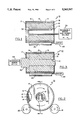
- FIG. 1 is a sectional view taken along line 1--1 of FIG. 2 and showing the rotor of an ECM with an induction coil located therein:
- FIG. 2 is a partially cutaway end view of the rotor of an ECM showing the induction coil and motorized rollers;
- FIG. 3 a sectional view corresponding to FIG. 1 and showing the insertion of the crankshaft into the heated rotor;
- FIG. 4 is a flow diagram of the assembly process.
- Rotor 10 generally designates the rotor of an ECM.
- Rotor 10 includes a generally cylindrical backiron member 12 having an axial bore 13 and having a plurality of thin magnetic elements or laminations 15 secured to the outer peripheral surface of the backiron 12 by an adhesive or other suitable means 14.
- the magnetic elements or laminations are made of ferromagnetic materials such as ferrite, a ceramic material, but may also be a neodymium or other high energy magnet.
- Ferromagnetic elements 15 are covered by stainless steel sheath 16 and the ends of rotor 10 are covered by annular aluminum end plates 17 and 18, respectively. Referring to FIG. 2, it will be noted that rotor 10 is supported on two rollers, 20 and 21 which define a support mechanism.
- roller 20 is illustrated in FIG. 1 as being driven by motor 22. However, if necessary, or desired, both of the rollers 20 and 21 can be driven. With roller 20 driven by motor 22 and rotor 10 placed on rollers 20 and 21, the rotor 10 will be driven in the opposite direction from roller 20.
- reversible motor and power source 30 is capable of placing bent hairpin induction coil 32 within bore 13 and withdrawing it therefrom and for powering the coil 32 when it is within bore 13.
- the use of the preferred bent hairpin requires the rotating of rotor 10 with respect to coil 32 in order to provide uniform heat penetration.
- coil 32 is withdrawn from bore 13 and crankshaft 40 is inserted in bore 13 by reversible motor 42, as illustrated, or manually. Or, alternatively, the rotor 10 is placed on crankshaft 40.
- the induction coil 32 and its power are selected such that the coil 32 is spaced from bore 13 so that uniform heat is distributed to the surface of bore 13 of rotating rotor 10.
- the coil 32 only provides induction heating for a portion of the radial distance originating at bore 13 by precisely regulating the frequency and power with the rest of rotor being heated only by conduction.
- coil 32 is withdrawn from bore 13 and crankshaft 40 is quickly inserted in bore 13.
- the coil 32 and its power will be selected for a specific rotor. For one rotor the best results were achieved with a frequency of about 145 kilohertz and 12 kilowatts of power applied for 30 seconds.
- ECM rotor 10 is heated inductively to expand the core or backiron portion 12 allowing it to shrink fit over crankshaft 40.
- rotor 10 is placed on the support mechanism defined by rollers 20 and 21.
- either internal style bent hairpin induction coil 32 is placed in bore 13 of the rotor 10 by reversible motor 30 as indicated by block 110.
- rotor 10 and the support mechanism are moved so that rotor 10 is moved onto induction coil 32, as indicated by block 115.
- motor 22 is started and rotor 10 is rotated by motor driven roller 20. Power is supplied to coil 32 as indicated by block 130 and heats rotor 10 from the inside-out.
- the power is supplied at high frequency and the coil 32 is designed so that the limit of heating depth can be controlled via coil design, induction power and frequencies so as to match the requirements of the rotor 10.
- the heating of bore 13 is terminated, as indicated by block 140, and motor 22 is stopped thereby stopping the rotation of rotor 10, as indicated by block 150.
- coil 32 is withdrawn from bore 13 by motor 30 or rotor 10 is removed from coil 32. With coil 32 and rotor 10 separated, rotor 10 is quickly oriented with respect to crankshaft 40, as indicated by block 160.
- crankshaft 40 is swiftly thrust onto crankshaft 40, as indicated by block 170, or crankshaft 40 is inserted into heated rotor 10 by reversible motor 42 or manually, as indicated by block 175.
- crankshaft 40 which is at ambient temperature, is placed in bore 13 of heated rotor 10 it acts as a heat sink relative to the rotor 10.
- the rotor 10 cools to a shrink fit on crankshaft 40, as indicated by block 180.
- the crankshaft and rotor assembly are then removed from the support mechanism as indicated by block 190.
- the foregoing method and apparatus provides fast heating so that it supports "on demand” processing, is economical since it only heats and therefore only expands the area requiring heat, leaves the outside of rotor 10 cool to the touch permitting easy bare hand installation of the rotor 10 onto crankshaft 40, does not cause loss of magnetic properties of the magnets 15, eliminates exceeding the maximum temperature of adhesive 14, does not cause destruction of the magnetic material because of the absence of thermal shock and essentially eliminates thermal stress because heat conduction takes place with respect to the crankshaft which is acting as a heat sink as well as flowing to the outside surface of the core 12.
Landscapes
- Engineering & Computer Science (AREA)
- Manufacturing & Machinery (AREA)
- Power Engineering (AREA)
- General Engineering & Computer Science (AREA)
- Mechanical Engineering (AREA)
- Manufacture Of Motors, Generators (AREA)
- General Induction Heating (AREA)
Abstract
An internal induction coil is used to heat the rotor of an ECM. This provides a localized heating and dilation of the bore of the rotor prior to the heating of the outer surface of the rotor. The crankshaft is located in the heated bore and acts as a heat sink. As a result, the outer surface of the rotor is not heated such as might cause the loss of magnetic properties.
Description
This application is a division of application Ser. No. 07/519,695, filed May 4, 1990, and now U.S. Pat. No. 5,279,027.
As disclosed in U.S. Pat. No. 4,876,492, an electronically commutated motor, ECM, includes a permanent magnet rotor assembly. The rotor assembly has a low reluctance core formed as an annular cylindrical ferromagnetic member generally referred to as backiron. The backiron is surrounded by a number of thin flat angular ferromagnetic elements or laminations secured to the outer peripheral surface of the backiron so as to establish constant magnetic polar regions with north-south polarizations. The thin ferromagnetic elements are made of permanent magnetic material such as Alnico and are secured, as by adhesive bonding, to the backiron. The thin ferromagnetic elements are alternately polarized to provide constant magnetic polar regions.
Where a rotor is to be directly attached to a crankshaft, or the like, it is common practice to heat the rotor and place it on the crankshaft so as to be shrunk fit thereon upon the cooling of the rotor. Ferromagnetic materials, however, are subject to the loss of their magnetic properties when heated to their Currie temperature. As a result, it is conventional to secure the rotors of ECM's by slot and key or other suitable means other than shrink fitting. Where one member is attached to another by shrink fitting, it is conventional to heat one of the members by an external induction coil or to place it in a convection oven to cause its thermal expansion. The heated member is placed on the other member and allowed to cool to a shrink fit. In such a method, the heated member is heated as a unit since the interior bore must be thermally expanded.
The present invention is directed to a method and apparatus for securing members together by a shrink fit. The invention is particularly applicable for securing the rotor of an ECM to a crankshaft, but is advantageous in any shrink fitting operation where one member is heated to permit its attachment to another member. Specifically, the present invention uses an induction coil to provide a localized heating and expansion of one member which can then be placed over or receive the other member to which it is to be shrink fit. Because the heating is localized, less energy is required, the ECM rotor magnets are not destroyed, there are no problems due to differential heating of dissimilar materials, the external surface remains cool and can be handled without the use of special tools. Further, because the core is heated by conduction between its middle and outside surface, thermal stresses are minimized since the crankshaft acts as a heat sink upon assembly.
It is an object of this invention to provide a method and apparatus for securing the rotor of an ECM to a crankshaft by shrink fit.
It is another object of this invention to provide a method and apparatus for the localized heating of a member.
It is a further object of this invention to provide a method and apparatus for heating the rotor of an ECM without the loss of magnetic properties.
It is an additional object of this invention to provide an energy efficient method and apparatus for securing members by shrink fit. These objects, and others as will become apparent hereinafter, are accomplished by the present invention.
Basically, an induction coil is placed in a bore or aperture in a member and then energized. Inductive penetration and heating takes place within a finite radial distance from the coil with heating by conduction taking place in the portion of the member at a greater radial distance then the inductive penetration. When the material surrounding the bore or aperture is sufficiently heated and before the member is fully heated by conduction, the coil is withdrawn and a second member at ambient temperature is inserted into the bore or aperture. The second member acts as a heat sink reducing the heat available to the outer portions of the heated member and the heated member cools and is secured to the second member with a shrink fit.
For a fuller understanding of the present invention, reference should now be made to the following detailed description thereof taken in conjunction with the accompanying drawings wherein:
FIG. 1 is a sectional view taken along line 1--1 of FIG. 2 and showing the rotor of an ECM with an induction coil located therein:
FIG. 2 is a partially cutaway end view of the rotor of an ECM showing the induction coil and motorized rollers;
FIG. 3 a sectional view corresponding to FIG. 1 and showing the insertion of the crankshaft into the heated rotor; and
FIG. 4 is a flow diagram of the assembly process.
In FIGS. 1-3, the numeral 10 generally designates the rotor of an ECM. Rotor 10 includes a generally cylindrical backiron member 12 having an axial bore 13 and having a plurality of thin magnetic elements or laminations 15 secured to the outer peripheral surface of the backiron 12 by an adhesive or other suitable means 14. Typically the magnetic elements or laminations are made of ferromagnetic materials such as ferrite, a ceramic material, but may also be a neodymium or other high energy magnet. Ferromagnetic elements 15 are covered by stainless steel sheath 16 and the ends of rotor 10 are covered by annular aluminum end plates 17 and 18, respectively. Referring to FIG. 2, it will be noted that rotor 10 is supported on two rollers, 20 and 21 which define a support mechanism. To avoid synchronization problems, preferably only one of the rollers is driven. Roller 20 is illustrated in FIG. 1 as being driven by motor 22. However, if necessary, or desired, both of the rollers 20 and 21 can be driven. With roller 20 driven by motor 22 and rotor 10 placed on rollers 20 and 21, the rotor 10 will be driven in the opposite direction from roller 20. Referring now to FIG. 1, reversible motor and power source 30 is capable of placing bent hairpin induction coil 32 within bore 13 and withdrawing it therefrom and for powering the coil 32 when it is within bore 13. The use of the preferred bent hairpin requires the rotating of rotor 10 with respect to coil 32 in order to provide uniform heat penetration. When rotor 10 is heated sufficiently, coil 32 is withdrawn from bore 13 and crankshaft 40 is inserted in bore 13 by reversible motor 42, as illustrated, or manually. Or, alternatively, the rotor 10 is placed on crankshaft 40.
The induction coil 32 and its power are selected such that the coil 32 is spaced from bore 13 so that uniform heat is distributed to the surface of bore 13 of rotating rotor 10. The coil 32 only provides induction heating for a portion of the radial distance originating at bore 13 by precisely regulating the frequency and power with the rest of rotor being heated only by conduction. When the bore 13 is heated so as to be dilated sufficiently, coil 32 is withdrawn from bore 13 and crankshaft 40 is quickly inserted in bore 13. The coil 32 and its power will be selected for a specific rotor. For one rotor the best results were achieved with a frequency of about 145 kilohertz and 12 kilowatts of power applied for 30 seconds. This permitted the insertion of the crankshaft 40 into bore 13 while the surface of rotor 10 as defined by sheath 16 remained cool to the touch for well past 30 seconds after the coil 32 was removed from bore 13. The temperature realized at the surface of bore 13 never reaches the magnetic elements 15 or the adhesive 14 which would be destroyed thereby.
In operation, ECM rotor 10 is heated inductively to expand the core or backiron portion 12 allowing it to shrink fit over crankshaft 40. Specifically, as shown in FIG. 4 and indicated by block 100, rotor 10 is placed on the support mechanism defined by rollers 20 and 21. Then, either internal style bent hairpin induction coil 32 is placed in bore 13 of the rotor 10 by reversible motor 30 as indicated by block 110. Or, rotor 10 and the support mechanism are moved so that rotor 10 is moved onto induction coil 32, as indicated by block 115. Then, as indicated by block 120, motor 22 is started and rotor 10 is rotated by motor driven roller 20. Power is supplied to coil 32 as indicated by block 130 and heats rotor 10 from the inside-out. The power is supplied at high frequency and the coil 32 is designed so that the limit of heating depth can be controlled via coil design, induction power and frequencies so as to match the requirements of the rotor 10. With the interior of rotor 10 heated and bore 13 optimally enlarged as a result, the heating of bore 13 is terminated, as indicated by block 140, and motor 22 is stopped thereby stopping the rotation of rotor 10, as indicated by block 150. Then, coil 32 is withdrawn from bore 13 by motor 30 or rotor 10 is removed from coil 32. With coil 32 and rotor 10 separated, rotor 10 is quickly oriented with respect to crankshaft 40, as indicated by block 160. Then, either rotor 10 is swiftly thrust onto crankshaft 40, as indicated by block 170, or crankshaft 40 is inserted into heated rotor 10 by reversible motor 42 or manually, as indicated by block 175. When crankshaft 40, which is at ambient temperature, is placed in bore 13 of heated rotor 10 it acts as a heat sink relative to the rotor 10. Thus, the rotor 10 cools to a shrink fit on crankshaft 40, as indicated by block 180. The crankshaft and rotor assembly are then removed from the support mechanism as indicated by block 190.
The foregoing method and apparatus provides fast heating so that it supports "on demand" processing, is economical since it only heats and therefore only expands the area requiring heat, leaves the outside of rotor 10 cool to the touch permitting easy bare hand installation of the rotor 10 onto crankshaft 40, does not cause loss of magnetic properties of the magnets 15, eliminates exceeding the maximum temperature of adhesive 14, does not cause destruction of the magnetic material because of the absence of thermal shock and essentially eliminates thermal stress because heat conduction takes place with respect to the crankshaft which is acting as a heat sink as well as flowing to the outside surface of the core 12.
Although the invention has been illustrated and described with the rotor remaining in position while the coil is inserted and withdrawn followed by the insertion of the crankshaft. The rotor could be placed over the coil 32 and onto the crankshaft 40. The steps may be done mechanically, as described, or by hand. If done mechanically, the removal of the coil 32 and the insertion of crankshaft 40 can be timed to be essentially concurrently to have the bore 13 as dilated as possible while permitting the heat sink effect of crankshaft 40 to take place as soon as possible. Further, although the description is specific to an ECM rotor it can be used to attach other members in a shrink fit where the loss of magnetic properties is not a factor but the reduced power requirements, bare hand manipulation, etc. can be of advantage. Thus, although a preferred embodiment of the present invention have been illustrated and described it is applicable to other uses. It is, therefore, intended that the present invention is to be limited only by the scope of the appended claims.
Claims (6)
1. A method for securing two members in a shrink fit comprising the steps of:
locating a means for providing localized heating within an opening in a first one of the two members;
with the means for providing localized heating in place within an opening in the first one of the two members, heating a localized portion of the first one of the two members by the means for providing localized heating;
separating the means for providing localized heating from the opening;
while the first one of the two members is still heated in a localized manner, locating a portion of the second one of the two members within the opening whereby the second one of the two members acts as a heat sink with respect to the first one of the two members and the first one of the two members shrink fits onto the second one of the two members.
2. The method of claim 1 wherein the step of heating is performed by an induction coil.
3. A method for securing a rotor of an ECM onto a crankshaft in a shrink fit comprising the steps of:
locating a means for providing localized heating within a bore in the rotor;
heating a localized portion of the rotor surrounding the bore;
separating the means for providing localized heating from the bore;
while the rotor is still heated in a localized manner, locating the crankshaft within the bore whereby the crankshaft acts as a heat sink with respect to the rotor and the rotor shrink fits onto the second member.
4. The method of claim 3 wherein the step of heating is performed by an induction coil.
5. The method of claim 4 wherein the exterior surface of the rotor remains at essentially ambient temperature.
6. The method of claim 3 wherein the crankshaft is at ambient temperature when located in the rotor.
Priority Applications (1)
| Application Number | Priority Date | Filing Date | Title |
|---|---|---|---|
| US08/121,632 US5363547A (en) | 1990-05-04 | 1993-09-16 | Method for attaching rotors to crankshafts |
Applications Claiming Priority (4)
| Application Number | Priority Date | Filing Date | Title |
|---|---|---|---|
| US07/519,695 US5279027A (en) | 1990-05-04 | 1990-05-04 | Apparatus for attaching rotors to crankshafts |
| US08/121,632 US5363547A (en) | 1990-05-04 | 1993-09-16 | Method for attaching rotors to crankshafts |
| EP93630070A EP0645873A1 (en) | 1990-05-04 | 1993-09-16 | Method and apparatus for attaching rotors to crankshafts |
| BR9303871A BR9303871A (en) | 1990-05-04 | 1993-09-23 | Apparatus and process for fixing two members in a shrink fit relationship |
Related Parent Applications (1)
| Application Number | Title | Priority Date | Filing Date |
|---|---|---|---|
| US07/519,695 Division US5279027A (en) | 1990-05-04 | 1990-05-04 | Apparatus for attaching rotors to crankshafts |
Publications (1)
| Publication Number | Publication Date |
|---|---|
| US5363547A true US5363547A (en) | 1994-11-15 |
Family
ID=27160080
Family Applications (2)
| Application Number | Title | Priority Date | Filing Date |
|---|---|---|---|
| US07/519,695 Expired - Lifetime US5279027A (en) | 1990-05-04 | 1990-05-04 | Apparatus for attaching rotors to crankshafts |
| US08/121,632 Expired - Lifetime US5363547A (en) | 1990-05-04 | 1993-09-16 | Method for attaching rotors to crankshafts |
Family Applications Before (1)
| Application Number | Title | Priority Date | Filing Date |
|---|---|---|---|
| US07/519,695 Expired - Lifetime US5279027A (en) | 1990-05-04 | 1990-05-04 | Apparatus for attaching rotors to crankshafts |
Country Status (3)
| Country | Link |
|---|---|
| US (2) | US5279027A (en) |
| EP (1) | EP0645873A1 (en) |
| BR (1) | BR9303871A (en) |
Cited By (1)
| Publication number | Priority date | Publication date | Assignee | Title |
|---|---|---|---|---|
| US10411531B2 (en) | 2015-03-26 | 2019-09-10 | Skf Magnetic Mechatronics | Stator assembly and magnetic bearing or electric motor having such a stator assembly |
Families Citing this family (6)
| Publication number | Priority date | Publication date | Assignee | Title |
|---|---|---|---|---|
| CN100409999C (en) * | 2004-03-09 | 2008-08-13 | 沪东重机有限公司 | Red sleeve method for main shaft and rotor of large equipment |
| JP5799759B2 (en) * | 2011-11-09 | 2015-10-28 | 日産自動車株式会社 | Heat treatment method and heat treatment apparatus for rotor core |
| WO2015040482A2 (en) * | 2013-09-17 | 2015-03-26 | Toyota Jidosha Kabushiki Kaisha | Rotor core heating device and rotor core shrink-fitting method |
| JP6274096B2 (en) * | 2014-09-17 | 2018-02-07 | トヨタ自動車株式会社 | Rotor core heating method and heating apparatus |
| GB2562196B (en) * | 2016-09-08 | 2020-03-04 | Protean Electric Ltd | A method and arrangement for assembling an electric motor or generator |
| US10920592B2 (en) | 2017-12-15 | 2021-02-16 | General Electric Company | System and method for assembling gas turbine rotor using localized inductive heating |
Citations (2)
| Publication number | Priority date | Publication date | Assignee | Title |
|---|---|---|---|---|
| US2145864A (en) * | 1934-07-12 | 1939-02-07 | Ohio Crankshaft Co | Method of making hardened surface articles |
| US3345732A (en) * | 1964-06-11 | 1967-10-10 | Gen Dynamics Corp | Method of shrink fitting and apparatus therefor |
Family Cites Families (5)
| Publication number | Priority date | Publication date | Assignee | Title |
|---|---|---|---|---|
| GB1034984A (en) * | 1964-05-04 | 1966-07-06 | John Michael Langham | Improvements in or relating to marine propellers |
| DE3535511A1 (en) * | 1984-10-06 | 1986-04-17 | Ngk Spark Plug Co., Ltd., Nagoya, Aichi | Connecting arrangement between a ceramic shaft and a metal shaft |
| US4729160A (en) * | 1985-08-14 | 1988-03-08 | Kollmorgen Technologies Corporation | Method for manufacturing a composite sleeve for an electric motor |
| JPH01109029A (en) * | 1987-10-21 | 1989-04-26 | Hitachi Ltd | Shrinkage fitting method and device for rotor of compressor |
| JPH0382349A (en) * | 1989-08-22 | 1991-04-08 | Sanyo Electric Co Ltd | Manufacture of motor |
-
1990
- 1990-05-04 US US07/519,695 patent/US5279027A/en not_active Expired - Lifetime
-
1993
- 1993-09-16 US US08/121,632 patent/US5363547A/en not_active Expired - Lifetime
- 1993-09-16 EP EP93630070A patent/EP0645873A1/en not_active Ceased
- 1993-09-23 BR BR9303871A patent/BR9303871A/en not_active Application Discontinuation
Patent Citations (2)
| Publication number | Priority date | Publication date | Assignee | Title |
|---|---|---|---|---|
| US2145864A (en) * | 1934-07-12 | 1939-02-07 | Ohio Crankshaft Co | Method of making hardened surface articles |
| US3345732A (en) * | 1964-06-11 | 1967-10-10 | Gen Dynamics Corp | Method of shrink fitting and apparatus therefor |
Cited By (1)
| Publication number | Priority date | Publication date | Assignee | Title |
|---|---|---|---|---|
| US10411531B2 (en) | 2015-03-26 | 2019-09-10 | Skf Magnetic Mechatronics | Stator assembly and magnetic bearing or electric motor having such a stator assembly |
Also Published As
| Publication number | Publication date |
|---|---|
| EP0645873A1 (en) | 1995-03-29 |
| US5279027A (en) | 1994-01-18 |
| BR9303871A (en) | 1995-05-23 |
Similar Documents
| Publication | Publication Date | Title |
|---|---|---|
| KR100500860B1 (en) | Improvements in high speed rotor shafts | |
| US5363547A (en) | Method for attaching rotors to crankshafts | |
| US6169353B1 (en) | Method for manufacturing a rotor having superconducting coils | |
| US4339874A (en) | Method of making a wedge-shaped permanent magnet rotor assembly | |
| EP0212552B1 (en) | Method for producing a composite sleeve for an electric motor | |
| US6345433B1 (en) | Fabrication method for high speed induction motor rotor | |
| JPH02231945A (en) | Method and apparatus for manufacturing permanent magnet rotor | |
| US4242610A (en) | Wedge-shaped permanent magnet rotor assembly | |
| US20060192455A1 (en) | Threaded inner sleeve for generator magnet | |
| JP4638720B2 (en) | Method for shrink coupling a rotary tool with a cylindrical shaft | |
| MX2007012088A (en) | Electrical rotating machine comprising an intermediate sleeve interposed between the shaft and the polar wheels and method for making the rotor. | |
| US6531795B2 (en) | Drive system | |
| EP0709838B1 (en) | Expanded tubular hub disk pack assembly clamp | |
| US6325298B1 (en) | Induction heat generator for the reduction of emissions from an internal combustion engine | |
| JP2001069732A (en) | Method of fixing stator winding and rotating electric machine | |
| JPH07111764A (en) | Method and apparatus for mounting a rotor on a crankshaft | |
| JP2001339886A (en) | Rotor, method of manufacturing the same, and rotating machine | |
| JP2007152517A (en) | Rotor heating apparatus and rotor manufacturing method | |
| US4849047A (en) | Vibration damper bonding system | |
| JP2001136692A (en) | Inner rotor motor and method of manufacturing rotor thereof | |
| TW200538228A (en) | Attenuating adaptor for an inductive shrinkage appliance | |
| JPH08275470A (en) | Rotor of permanent magnet type rotating electric machine and manufacturing method thereof | |
| US4333223A (en) | Shielding cylinder and method of manufacture | |
| JP2001346348A (en) | Rotor of compressor and method of assembling compressor parts | |
| JP2003259611A (en) | Method for manufacturing outer rotor and apparatus for manufacturing the same |
Legal Events
| Date | Code | Title | Description |
|---|---|---|---|
| STCF | Information on status: patent grant |
Free format text: PATENTED CASE |
|
| REMI | Maintenance fee reminder mailed | ||
| FPAY | Fee payment |
Year of fee payment: 4 |
|
| SULP | Surcharge for late payment | ||
| FPAY | Fee payment |
Year of fee payment: 8 |
|
| FPAY | Fee payment |
Year of fee payment: 12 |