US5362150A - Fluid mixer - Google Patents
Fluid mixer Download PDFInfo
- Publication number
- US5362150A US5362150A US07/986,650 US98665092A US5362150A US 5362150 A US5362150 A US 5362150A US 98665092 A US98665092 A US 98665092A US 5362150 A US5362150 A US 5362150A
- Authority
- US
- United States
- Prior art keywords
- fluid
- section
- mixer
- entry section
- inlet conduits
- Prior art date
- Legal status (The legal status is an assumption and is not a legal conclusion. Google has not performed a legal analysis and makes no representation as to the accuracy of the status listed.)
- Expired - Fee Related
Links
Images

Classifications
-
- B—PERFORMING OPERATIONS; TRANSPORTING
- B01—PHYSICAL OR CHEMICAL PROCESSES OR APPARATUS IN GENERAL
- B01F—MIXING, e.g. DISSOLVING, EMULSIFYING OR DISPERSING
- B01F25/00—Flow mixers; Mixers for falling materials, e.g. solid particles
- B01F25/20—Jet mixers, i.e. mixers using high-speed fluid streams
- B01F25/25—Mixing by jets impinging against collision plates
Definitions
- the present invention generally relates to a fluid mixer and, in particular, relates to one such fluid mixer having a plurality of fluid inlet conduits terminating proximate a first surface of a chamber such that fluids exiting the conduits impinge upon a single location of the first surface.
- fluid and the derivatives thereof will be taken to include liquids, gases supercritical fluids and generally all flow compatible areas defined by a typical thermodynamic state diagram. However, for the sake of consistency and by way of example only, the following description will primarily refer to gases.
- the manifold type of gas mixer usually include a straight tube having a plurality of inputs and a single output located distal the inputs.
- the straight tube has a sealed end(s) to force the gases toward the output.
- the primary disadvantage of the manifold gas mixer is that for gases having different flow velocities, hence, different densities for constant tube diameters, the flow in the manifold may readily become stratified rather than mixed.
- the expansion chamber type of gas mixer usually includes a plurality of inlet conduits on one wall thereof and a single outlet conduit on the opposing wall.
- the principle of the expansion chamber gas mixer is to allow the incoming gases to expand such that the forward flow velocity of the incoming gas is substantially reduced, preferably to close to zero forward velocity. In this manner the incoming gases expand and simultaneously mix.
- this type of gas mixer is disadvantageous since the actual mixing of the gases is substantially uncontrolled.
- a fluid mixer having a plurality of inlet conduits extending into and being directed toward one location of a surface of a chamber.
- FIG. 1 which is a cross-sectional view of a fluid mixer embodying the principles of the present invention.
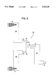
- FIG. 2 which is a schematic diagram of a system particularly adapted for mixing a plurality of fluids and embodying the principles of the present invention.
- a fluid mixer generally indicated at 10 in FIG. 1 and embodying the principles of the present invention, includes a chamber 12 having a first surface 14 disposed opposite a plurality of input conduits 16.
- the mixer 10 includes a fluid outlet conduit 18 disposed distal and opposite to the inlet conduits 16.
- the chamber 12 will be discussed as if it were a number of overlapping sections wherein various physical mixing reactions occur. More specifically, as shown by the dashed lines in FIG. 1, the chamber 12 is described herein as having a fluid entry section 20, a fluid expansion section 22, and a fluid exit section 24.
- the plurality of inlet conduits 16 enter through one end 26 of the fluid entry section 20 of the chamber 12 and are directed toward a single location 28 on the opposing first surface 14 of the chamber 12.
- the inlet conduits 16 are disposed to ensure that the gas inlet conduits 16 are directed toward the single location 28 and are spaced away from that surface 14 a distance that is less than four times the diameter of the conduits.
- the distance therefrom to the single location 28 should be less than four times the inner diameter of the smaller conduit.
- the mixed or combined gas stream forms a jet stream that expands directly into a first portion 35 of the fluid expansion section 22.
- the jet stream expands in all directions from the first surface 14.
- the surrounding walls 29 defining the chamber 12 prevent continued expansion in those directions, a substantial portion of the jet expands into the expansion section 22 as a jet.
- another portion of the expanding jet expands into the confined areas 31 of the fluid entry section 20 and further assists the mixing of the gases.
- the gas stream impinging upon the solid first surface 14 expands therefrom at an angle 30 of about 7° into the fluid expansion section 22.
- the expanding stream is depicted in FIG. 1 as expanding into the first portion 35 of the fluid expansion section 22.
- the deflection of a fluid jet is taken to define the turning of the jet from the point of stagnation into an expansion stream.
- the flow within the wake of the jet becomes very turbulent, thereby more thoroughly mixing the gases.
- the portion of the gas mixture that expands into the confined areas 31 of the fluid entry section 20 flow into the void areas 37 of the fluid expansion section 22 thereby establishing a quasi-stable jet having a larger relative velocity than the jet expanding into the portion 35 of the fluid expansion section 22.
- the friction created by the different velocities causes further mixing. More specifically, the portions of the gas jet that expands into the void areas 37 of the expansion section 22 creates a diffusion boundary 33 with the jet.
- the fluid mixer 10 of the present invention ensures the thorough fluid mixing independent of the flow velocities of the incoming fluids.
- the expanding gas stream impinges upon a wall 32 of the exit section 24 that, in the preferred embodiment, is disposed in the path of the expanding stream and in a plane perpendicular to the plane of the first surface 14.
- the wall 32 is located away from the first surface 14 a distance such that the expanding stream has a minimum velocity and, as a result, the expansion type mixing effect is fully utilized.
- the mixed gas, upon impinging on the exit section 24, is reaccelerated, again at an angle of about seven degrees, toward the outlet conduit 18 that is disposed, in the preferred embodiment, in a second surface which is in a plane substantially parallel to the plane of the first surface 14.
- the outlet conduit 18 is longitudinally displaced in a direction opposite to the inlet conduits 16 with respect to the plane of the first surface 14 by the distance required to expand the gas flow across the cross-sectional area of the expansion section 22 of the chamber 12.
- the outlet conduit 18 has the same diameter as one of the inlet conduits 16.
- the inside diameter of the outlet conduit 16 can be chosen to control the flow velocity of the mixed gas.
- the fluid exit section 24 of the chamber 12 thus has a length such that when the expanding gas stream impinges thereon, the entire cross-sectional portion thereof is filled.
- the first mixing stage being the convergence of the gases from the ends of the inlet conduits 16 as the fluid streams move toward the same location 28 on the first surface 14 of the entry section 20 of the chamber 12.
- the second mixing stage occurring at the location 28 where all conduit streams are directed and therefore turbulent flow causes further mixing as the gas streams which, at this point, is effectively a single gas stream that expands from the location 28 on the surface 14 at an angle of about 7° into the expansion section 22 of the chamber 12.
- the third mixing stage occurs within the expansion section 22 of the chamber 12 as the mixed gas expands toward the exit section 24 of the chamber 12.
- the fourth mixing stage occurs when the gas flow with a minimal velocity impinges upon the wall of the exit chamber, and the fifth mixing stage occurs within the exit chamber where the gas stream, expanding from the exit section wall, mixes and expands into the exit section. It will be understood that although five mixing action have been specifically related, other mixing actions, such as the mixing along the jet boundary 33 also occur.
- the chamber 12 is circular in cross-section although any cross-sectional shape can be used.
- the length of the expansion section 22 of the chamber 12 is determined by the diameter of the chamber 12 and the fact that the gas stream reflects from the first surface 14 at 7°. That is, recognizing the angle of expansion of the jet, the length of the expansion section 22 is selected to ensure that the jet expands to fill the cross-sectional area of the expansion section 22 and provides a minimal translational velocity at the wall 32 or the exit section 24.
- the chamber 12 can be formed by the use of conventional tube, pipe or gas fittings.
- the fluid entry section 20 and the fluid exit section 24 can be right angled fittings and the expansion section 22 can be a straight length of tubing.
- the fluid entry section 20 and the fluid exit section 24 can be fight angled fittings with the outside diameter of the exit section 24 being chosen to fit into the inside diameter of the fluid entry section 22 whereby the fluid expansion section 22 is formed by joining the two fittings.
- the system 34 includes a plurality of fluid mixers, 10A, 10B, and 10C each having a plurality of inlet conduits 16 and a single outlet conduit 18.
- the outlet conduits 18 of the two fluid mixers, 10A and 10B are interconnected to the inputs 36 and 38 of a "T" fitting 40.
- the output 42 of the "T" fitting 40 serves as the inlet conduit 16 of the fluid mixer 10C.
- the third fluid mixer 10C has a single inlet conduit 16.
- outlet conduits 18 of each of the fluid mixers, 10A and 10B could become a single inlet conduit 16 of the fluid mixer 10C.
- the number of fluid mixers in any particular system is dependent, inter alia, upon the number of gases to be mixed as well as the number of inlet conduits each fluid mixer 10 can practically sustain. It is contemplated, of course, that the fluid miser 10 can be appropriately cascaded to provide the uniform mixing of any number of gases.
Abstract
Description
Claims (13)
Priority Applications (1)
| Application Number | Priority Date | Filing Date | Title |
|---|---|---|---|
| US07/986,650 US5362150A (en) | 1992-12-08 | 1992-12-08 | Fluid mixer |
Applications Claiming Priority (1)
| Application Number | Priority Date | Filing Date | Title |
|---|---|---|---|
| US07/986,650 US5362150A (en) | 1992-12-08 | 1992-12-08 | Fluid mixer |
Publications (1)
| Publication Number | Publication Date |
|---|---|
| US5362150A true US5362150A (en) | 1994-11-08 |
Family
ID=25532624
Family Applications (1)
| Application Number | Title | Priority Date | Filing Date |
|---|---|---|---|
| US07/986,650 Expired - Fee Related US5362150A (en) | 1992-12-08 | 1992-12-08 | Fluid mixer |
Country Status (1)
| Country | Link |
|---|---|
| US (1) | US5362150A (en) |
Cited By (8)
| Publication number | Priority date | Publication date | Assignee | Title |
|---|---|---|---|---|
| GB2326356A (en) * | 1998-03-21 | 1998-12-23 | Sobegina Trading Limited | Preparing emulsions by reflecting a liquid mixture |
| US6086241A (en) * | 1993-07-14 | 2000-07-11 | Siemens Aktiengesellschaft | Combined mixing and deflection unit |
| EP1025897A1 (en) * | 1995-05-12 | 2000-08-09 | Halliburton Energy Services, Inc. | Apparatus and method for mixing |
| US20040129829A1 (en) * | 2002-11-22 | 2004-07-08 | Michael Hoerle | Method and apparatus for on-site mixing of liquid deicer |
| USRE40407E1 (en) | 1999-05-24 | 2008-07-01 | Vortex Flow, Inc. | Method and apparatus for mixing fluids |
| US20100230516A1 (en) * | 2009-03-12 | 2010-09-16 | Solie John B | Mixing nozzle for plural component materials |
| US20110305101A1 (en) * | 2007-08-13 | 2011-12-15 | Fred Brouillette | System for Manufacturing a Proportional Slurry |
| CN107335348A (en) * | 2017-08-21 | 2017-11-10 | 清华大学 | Strengthen the gas-liquid two-phase mixing arrangement of mixing |
Citations (8)
| Publication number | Priority date | Publication date | Assignee | Title |
|---|---|---|---|---|
| US1043644A (en) * | 1912-02-06 | 1912-11-05 | Robert O Thomas | Direct feed-chamber for boilers. |
| DE666515C (en) * | 1932-12-13 | 1938-10-21 | Elektro Technik G M B H | Air foam generator |
| US2965695A (en) * | 1957-12-03 | 1960-12-20 | Shell Oil Co | Method and apparatus for repetitive mixing of fluids |
| US3918687A (en) * | 1972-03-17 | 1975-11-11 | Hubers Gerd Jan | Structure for encapsulating articles with viscous compositions such as casting resins |
| US4428679A (en) * | 1979-04-05 | 1984-01-31 | Swiss Aluminium Ltd. | Process for mixing and cooling electrode material |
| US5011293A (en) * | 1989-10-12 | 1991-04-30 | The United States Of America As Represented By The Secretary Of The Army | Emulsifier mixing cell |
| US5074671A (en) * | 1990-11-13 | 1991-12-24 | Dew Engineering And Development Limited | Mixing apparatus |
| US5082372A (en) * | 1991-05-22 | 1992-01-21 | Gas Technology Resources Flotron, Incorporated | Fluid mixing device |
-
1992
- 1992-12-08 US US07/986,650 patent/US5362150A/en not_active Expired - Fee Related
Patent Citations (8)
| Publication number | Priority date | Publication date | Assignee | Title |
|---|---|---|---|---|
| US1043644A (en) * | 1912-02-06 | 1912-11-05 | Robert O Thomas | Direct feed-chamber for boilers. |
| DE666515C (en) * | 1932-12-13 | 1938-10-21 | Elektro Technik G M B H | Air foam generator |
| US2965695A (en) * | 1957-12-03 | 1960-12-20 | Shell Oil Co | Method and apparatus for repetitive mixing of fluids |
| US3918687A (en) * | 1972-03-17 | 1975-11-11 | Hubers Gerd Jan | Structure for encapsulating articles with viscous compositions such as casting resins |
| US4428679A (en) * | 1979-04-05 | 1984-01-31 | Swiss Aluminium Ltd. | Process for mixing and cooling electrode material |
| US5011293A (en) * | 1989-10-12 | 1991-04-30 | The United States Of America As Represented By The Secretary Of The Army | Emulsifier mixing cell |
| US5074671A (en) * | 1990-11-13 | 1991-12-24 | Dew Engineering And Development Limited | Mixing apparatus |
| US5082372A (en) * | 1991-05-22 | 1992-01-21 | Gas Technology Resources Flotron, Incorporated | Fluid mixing device |
Cited By (18)
| Publication number | Priority date | Publication date | Assignee | Title |
|---|---|---|---|---|
| US6086241A (en) * | 1993-07-14 | 2000-07-11 | Siemens Aktiengesellschaft | Combined mixing and deflection unit |
| EP1025897A1 (en) * | 1995-05-12 | 2000-08-09 | Halliburton Energy Services, Inc. | Apparatus and method for mixing |
| GB2326356A (en) * | 1998-03-21 | 1998-12-23 | Sobegina Trading Limited | Preparing emulsions by reflecting a liquid mixture |
| USRE40407E1 (en) | 1999-05-24 | 2008-07-01 | Vortex Flow, Inc. | Method and apparatus for mixing fluids |
| US7168844B2 (en) * | 2002-11-22 | 2007-01-30 | Cargill, Inc. | Method and apparatus for on-site mixing of liquid deicer |
| US7461969B2 (en) | 2002-11-22 | 2008-12-09 | Cargill, Incorporated | Method and apparatus for on-site mixing of liquid deicer |
| US20070176138A1 (en) * | 2002-11-22 | 2007-08-02 | Michael Hoerle | Method and Apparatus for On-Site Mixing of Liquid Deicer |
| US20070177456A1 (en) * | 2002-11-22 | 2007-08-02 | Michael Hoerle | Method and Apparatus for On-Site Mixing of Liquid Deicer |
| US20040129829A1 (en) * | 2002-11-22 | 2004-07-08 | Michael Hoerle | Method and apparatus for on-site mixing of liquid deicer |
| US7438827B2 (en) | 2002-11-22 | 2008-10-21 | Cargill, Incorporated | Method and apparatus for on-site mixing of liquid deicer |
| US7461971B2 (en) | 2002-11-22 | 2008-12-09 | Cargill, Incorporated | Method and apparatus for on-site mixing of liquid deicer |
| US20070148359A1 (en) * | 2002-11-22 | 2007-06-28 | Michael Hoerle | Method and Apparatus for On-Site Mixing of Liquid Deicer |
| US20090008598A1 (en) * | 2002-11-22 | 2009-01-08 | Cargill, Incorporated | Method and apparatus for on-site mixing of liquid deicer |
| US20110305101A1 (en) * | 2007-08-13 | 2011-12-15 | Fred Brouillette | System for Manufacturing a Proportional Slurry |
| US8714809B2 (en) * | 2007-08-13 | 2014-05-06 | Texas Industries, Inc. | System for manufacturing a proportional slurry |
| US20100230516A1 (en) * | 2009-03-12 | 2010-09-16 | Solie John B | Mixing nozzle for plural component materials |
| CN107335348A (en) * | 2017-08-21 | 2017-11-10 | 清华大学 | Strengthen the gas-liquid two-phase mixing arrangement of mixing |
| CN107335348B (en) * | 2017-08-21 | 2020-05-05 | 清华大学 | Gas-liquid two-phase mixing device for enhancing mixing |
Similar Documents
| Publication | Publication Date | Title |
|---|---|---|
| US5597236A (en) | High/low viscosity static mixer and method | |
| US4179222A (en) | Flow turbulence generating and mixing device | |
| US7878705B2 (en) | Static mixing element and method of mixing a drilling liquid | |
| US4812049A (en) | Fluid dispersing means | |
| US3894302A (en) | Self-venting fitting | |
| US20060035183A1 (en) | Mixer | |
| US5492409A (en) | Device for mixing two fluids having different temperature | |
| US9242260B2 (en) | Directed multiport eductor and method of use | |
| WO1993016791A3 (en) | A two-phase supersonic flow system | |
| US5362150A (en) | Fluid mixer | |
| JPS60227820A (en) | Rapid inline mixer of two fluids | |
| JPH06277480A (en) | Device and method for turbulent mixing of gas | |
| JPH05200262A (en) | Stationary mixing member with deflection body and mixing device | |
| JPH0712313A (en) | Premixing burner | |
| US4815942A (en) | Axially-symmetric, jet-diffuser ejector | |
| US2426833A (en) | Apparatus for mixing fluids | |
| MXPA01006231A (en) | Mixer for mixing at least two flows of gas or other newtonian liquids. | |
| Lewellen et al. | Transonic swirling flow. | |
| US5765946A (en) | Continuous static mixing apparatus and process | |
| US5647201A (en) | Cavitating venturi for low reynolds number flows | |
| JPH0663371A (en) | Gas-liquid dissolving and mixing device | |
| GB2189843A (en) | Apparatus for mixing fluids | |
| US3540474A (en) | Rapid mixer | |
| US4735224A (en) | Method for stabilizing the flow of fluids at the time of expansion accompanied by kinetic energy degradation, a valve and a pressure reducer for carrying out said method | |
| US11014054B2 (en) | Fluid-gas mixer |
Legal Events
| Date | Code | Title | Description |
|---|---|---|---|
| AS | Assignment |
Owner name: HUGHES AIRCRAFT COMPANY, CALIFORNIA Free format text: ASSIGNMENT OF ASSIGNORS INTEREST.;ASSIGNOR:TAYLOR, WILLIAM D.;REEL/FRAME:006347/0524 Effective date: 19921208 |
|
| AS | Assignment |
Owner name: INTEGRATED PROCESS EQUIPMENT CORP., ARIZONA Free format text: ASSIGNMENT OF ASSIGNORS INTEREST;ASSIGNOR:HUGHES AIRCRAFT COMPANY;REEL/FRAME:007824/0119 Effective date: 19960201 |
|
| AS | Assignment |
Owner name: INTEGRATED PROCESS EQUIPMENT CORP., ARKANSAS Free format text: ASSIGNMENT OF ASSIGNORS INTEREST;ASSIGNOR:HUGHES AIRCRAFT COMPANY;REEL/FRAME:007991/0547 Effective date: 19960207 |
|
| AS | Assignment |
Owner name: FIRST INTERSTATE BANK OF ARIZONA, N.A., ARIZONA Free format text: SECURITY INTEREST;ASSIGNOR:INTEGRATED PROCESS EQUIPMENT;REEL/FRAME:008000/0438 Effective date: 19960424 |
|
| FEPP | Fee payment procedure |
Free format text: PAYOR NUMBER ASSIGNED (ORIGINAL EVENT CODE: ASPN); ENTITY STATUS OF PATENT OWNER: LARGE ENTITY |
|
| REMI | Maintenance fee reminder mailed | ||
| LAPS | Lapse for failure to pay maintenance fees | ||
| FP | Lapsed due to failure to pay maintenance fee |
Effective date: 19981108 |
|
| AS | Assignment |
Owner name: INTEGRATED PROCESS EQUIPMENT CORP., ARIZONA Free format text: RELEASE OF SECURITY AGREEMENT;ASSIGNOR:WELLS FARGO BANK, NATIONAL ASSOCIATION, AS AGENT, FORMERLY FIRST INTERSTATE BANK OF ARIZONA, N.A.;REEL/FRAME:009737/0571 Effective date: 19990203 |
|
| STCH | Information on status: patent discontinuation |
Free format text: PATENT EXPIRED DUE TO NONPAYMENT OF MAINTENANCE FEES UNDER 37 CFR 1.362 |