US5356332A - Coin mechanism - Google Patents
Coin mechanism Download PDFInfo
- Publication number
- US5356332A US5356332A US07/972,449 US97244993A US5356332A US 5356332 A US5356332 A US 5356332A US 97244993 A US97244993 A US 97244993A US 5356332 A US5356332 A US 5356332A
- Authority
- US
- United States
- Prior art keywords
- coin
- coins
- store
- denomination
- level
- Prior art date
- Legal status (The legal status is an assumption and is not a legal conclusion. Google has not performed a legal analysis and makes no representation as to the accuracy of the status listed.)
- Expired - Lifetime
Links
Images
Classifications
-
- G—PHYSICS
- G07—CHECKING-DEVICES
- G07F—COIN-FREED OR LIKE APPARATUS
- G07F5/00—Coin-actuated mechanisms; Interlocks
- G07F5/24—Coin-actuated mechanisms; Interlocks with change-giving
Definitions
- This invention relates to coin mechanisms.
- coin when used herein includes genuine coins, tokens, counterfeit coins and any other objects which may be inserted into a coin mechanism in an attempt to obtain any kind of goods or services.
- Coin mechanisms which test coins as to their acceptability and, if acceptable, indicate their denomination, and which in respect of at least some of the acceptable denominations, direct them to respective coin stores, these usually being in the form of coin tubes, which may have different diameters depending upon the particular coin denomination each is intended to contain, and which are adapted to hold the coins in a vertical stack face-to-face.
- a coin dispensing arrangement is provided for dispensing appropriate combinations of coins from the bottoms of the stacks for the purpose of giving change or providing prizes.
- there is usually a cashbox to which are directed coins which it is not intended to dispense either as change or as prizes, and also coins which might normally be directed to specific coin stores but which are accepted when the particular coin store in question is already full.
- auxiliary coin tube which is individually mountable to, and demountable from, the coin mechanism manually without the use of tools.
- the auxiliary coin tube is pre-loaded manually with coins of the frequently-used denomination and mounted to the coin mechanism. There are then available for dispensing whatever coins may be already in, or delivered to, the main coin tube for that denomination, plus the quantity of coins of that denomination contained in the auxiliary tube.
- An object of the present invention is to reduce the frequency with which a large-capacity coin store has to be manually replenished or replaced with a pre-loaded new one.
- the invention provides a coin mechanism comprising testing means for testing coins as to their acceptability, a substantially upright coin store adapted to contain a plurality of acceptable coins of a particular denomination up to an upper level, and a coin dispenser for dispensing coins from the lower end of the store, characterised in that said coin store is provided with a coin inlet located below said upper level, and in that means is provided for delivering acceptable coins of said denomination from the testing means through said inlet into the store.
- the store can also be replenished through the inlet, which can be positioned at a level at or below that to which coins can be delivered after having passed by gravity through the testing means and a coin separator which normally will be present for the purpose of separating different denominations of accepted coins and routing them to appropriate different destinations.
- a method of providing a coin mechanism which includes coin testing means, with coins of a particular denomination for being dispensed from the mechanism, comprising adding to the mechanism a substantially upright coin store pre-loaded to a predetermined level with such coins, accepting further coins of said denomination into the mechanism through said coin testing means, dispensing coins from said coin store, and when its contents are below a lower level, directing into the coin store at said lower level accepted coins of said denomination.
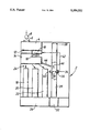
- FIGURE is side view of the internal configuration of a coin mechanism in accordance with the present invention.
- a coin mechanism 2 comprises coin testing means 4 having an inlet 6 for coins 8 to be tested.
- a microprocessor 10 is schematically illustrated, which normally will form part of the testing means.
- Microprocessor 10 compares measurements which are taken on the coin by the testing means with reference values appropriate to various different denominations of acceptable coins. When the comparison indicates that the coin inserted is acceptable the microprocessor provides a signal which causes power application to the actuator, normally a solenoid, of an accept/reject gate 12 which moves to a position such that the coin is delivered into a coin separator 14. If the coin is not found acceptable, the actuator of the accept/reject gate is not powered and so remains in a reject position such that the coin takes a path (not shown) back to the exterior of the mechanism where the customer can retrieve it.
- the actuator normally a solenoid
- the microprocessor 10 When a coin is acceptable, the microprocessor 10 also provides a signal, on output lines 16, indicative of the denomination of the coin.
- Coin tubes 18, 20 and 22 are provided each of which is intended in normal operation to receive accepted coins of a particular respective denomination.
- the coin separator 14 is actuated in response to the coin denomination as indicated by the output signal on line 16, so as to direct the coin, in dependence upon its denomination, towards the correct one of the tubes 18, 20 and 22 on one of the paths generally indicated by the arrows 24, if necessary via a suitable manifold.
- Actuation of the separator may consist of energising the appropriate ones of a plurality of solenoids which control the configuration of a set of gates, or the appropriate positioning of a motor which in turn positions a coin guide to direct a coin through the appropriate one of several outlets of the separator.
- a dispensing unit 26 is operated in well-known manner to dispense to the customer the appropriate coin or combination of coins from the bottoms of the coin stacks in tubes 18, 20 and 22, operation of the dispensing unit also being controlled by the microprocessor 10.
- an auxiliary coin tube 28 is provided which, outside the mechanism, can be pre-loaded with coins of that particular denomination to an upper level 30.
- the auxiliary coin tube 28 is individually mounted to the coin mechanism manually, the mounting arrangements being of any simple type not requiring the use of tools, such as snap-in or push-in fittings, so that mounting, and at a later time demounting, of the auxiliary coin tube can be done quickly and easily.
- the coin mechanism is fitted with an additional separate dispenser section 32 for dispensing from the bottom of the auxiliary coin tube.
- auxiliary coin tube 28 extends for virtually the whole of the available height within the coin mechanism and hence its capacity is maximised.
- microprocessor 10 may be programmed such that in the event that a lack of coins in tube 22 is indicated, it instead causes actuation of dispenser section 32 so as to dispense the necessary coins from auxiliary tube 28.
- a coin-level sensor of generally known kind which comprises a light source and a light detector together indicated at 36 on one side of the tube, respective apertures 38 on opposite sides of the tube, and a reflecting arrangement 40.
- a light beam passes from the light source through the first aperture, across the tube, through the second aperture, is reflected by the reflector 40 and returns along the same or a similar path through the apertures to the detector.
- Microprocessor 10 is programmed such that in this situation it will cause the separator 14 to direct coins of the denomination contained in tubes 22 and 28 always to tube 22 or, if that happens to be full, to a cashbox.
- the coin level detector associated with tube 28 does not have its beam broken, indicating that the coin level is below level 34, this is indicated to microprocessor 10 over line 42 and the microprocessor is programmed such that in that situation it will cause separator 14 to direct accepted coins of the denomination contained in tubes 22 and 28 through an additional exit shown as a chute 44 which delivers them to an angled slot 46 forming an inlet to auxiliary tube 28 located just above level 34. Since in this situation the existing coin level is below level 34 the coins in tube 28 will not obstruct the introduction of a further coin through entry 46. If the existing level were higher, there is a possibility that this would happen and that a jam would be caused in tube 28, but this avoided by the coin level detector once again inhibiting delivery of coins to tube 28 in response to detecting the increased coin level in tube 28.
- the stored coin level may be deduced by measuring when the coins are at a reference level, counting incoming & outgoing coins, and using the difference as an indicator of the present level relative to the reference level, this being a known technique.
- auxiliary coin tube 28 might be utilised simply to enable the basic mechanism to accept, store and dispense an extra, in this case a fourth, denomination of coin.
Abstract
Description
Claims (12)
Applications Claiming Priority (3)
| Application Number | Priority Date | Filing Date | Title |
|---|---|---|---|
| GB9016861A GB2246655B (en) | 1990-08-01 | 1990-08-01 | Coin mechanism |
| GB9016861.8 | 1990-08-01 | ||
| PCT/GB1991/001206 WO1992002906A1 (en) | 1990-08-01 | 1991-07-18 | Coin mechanism |
Publications (1)
| Publication Number | Publication Date |
|---|---|
| US5356332A true US5356332A (en) | 1994-10-18 |
Family
ID=10679979
Family Applications (1)
| Application Number | Title | Priority Date | Filing Date |
|---|---|---|---|
| US07/972,449 Expired - Lifetime US5356332A (en) | 1990-08-01 | 1991-07-18 | Coin mechanism |
Country Status (10)
| Country | Link |
|---|---|
| US (1) | US5356332A (en) |
| EP (1) | EP0541615B1 (en) |
| JP (1) | JPH06504388A (en) |
| AU (1) | AU8235091A (en) |
| DE (1) | DE69113469T2 (en) |
| ES (1) | ES2077237T3 (en) |
| GB (1) | GB2246655B (en) |
| IE (1) | IE912481A1 (en) |
| MX (1) | MX9100471A (en) |
| WO (1) | WO1992002906A1 (en) |
Cited By (6)
| Publication number | Priority date | Publication date | Assignee | Title |
|---|---|---|---|---|
| US6626749B2 (en) | 2000-05-30 | 2003-09-30 | Mohegan Tribal Gaming Authority | Coin hopper status detection and reporting system |
| US20040035672A1 (en) * | 1996-09-20 | 2004-02-26 | Mars Incorporated, A Delaware Corporation | Adaptable coin mechanism |
| US6910566B2 (en) | 2001-09-04 | 2005-06-28 | Asahi Seiko Co., Ltd. | Coin receiving and dispensing device |
| US20070029159A1 (en) * | 2005-08-02 | 2007-02-08 | Quattrini Victor A | Coin handling system for validation, sorting, and dispensing coins |
| US20160307386A1 (en) * | 2013-12-05 | 2016-10-20 | Nippon Conlux Co., Ltd. | Coin processing device |
| US20180151018A1 (en) * | 2015-03-24 | 2018-05-31 | Crane Payment Innovations Gmbh | Device for determining the filling level of coin tubes |
Citations (9)
| Publication number | Priority date | Publication date | Assignee | Title |
|---|---|---|---|---|
| GB925985A (en) * | 1958-09-25 | 1963-05-15 | John Henry Russell | Improvements in or relating to automatic vending machines |
| GB1415162A (en) * | 1971-12-18 | 1975-11-26 | Shaw A | Coin supply monitor |
| GB2065950A (en) * | 1979-11-12 | 1981-07-01 | Nippon Coinco Co Ltd | Safety Device for a Coin Changer |
| US4347924A (en) * | 1976-04-30 | 1982-09-07 | Nippon Coinco Co. Ltd. | Control system for a vending machine |
| US4374529A (en) * | 1979-10-08 | 1983-02-22 | Kabushiki Kaisha Nippon Coinco | Coin dispensing apparatus |
| GB2138192A (en) * | 1983-04-11 | 1984-10-17 | Coin Controls | Coin payout tubes |
| US4606360A (en) * | 1984-04-06 | 1986-08-19 | Mills Pearson O | Counting and wrapping of coins |
| EP0397353A2 (en) * | 1989-05-09 | 1990-11-14 | Sanden Corporation | Coin return control system for vending machines |
| US5052538A (en) * | 1987-10-01 | 1991-10-01 | Sanden Corporation | Coin handling apparatus |
-
1990
- 1990-08-01 GB GB9016861A patent/GB2246655B/en not_active Revoked
-
1991
- 1991-07-16 IE IE248191A patent/IE912481A1/en unknown
- 1991-07-18 AU AU82350/91A patent/AU8235091A/en not_active Abandoned
- 1991-07-18 EP EP91913648A patent/EP0541615B1/en not_active Expired - Lifetime
- 1991-07-18 US US07/972,449 patent/US5356332A/en not_active Expired - Lifetime
- 1991-07-18 JP JP3512556A patent/JPH06504388A/en active Pending
- 1991-07-18 WO PCT/GB1991/001206 patent/WO1992002906A1/en active IP Right Grant
- 1991-07-18 DE DE69113469T patent/DE69113469T2/en not_active Expired - Fee Related
- 1991-07-18 ES ES91913648T patent/ES2077237T3/en not_active Expired - Lifetime
- 1991-07-31 MX MX9100471A patent/MX9100471A/en not_active Application Discontinuation
Patent Citations (9)
| Publication number | Priority date | Publication date | Assignee | Title |
|---|---|---|---|---|
| GB925985A (en) * | 1958-09-25 | 1963-05-15 | John Henry Russell | Improvements in or relating to automatic vending machines |
| GB1415162A (en) * | 1971-12-18 | 1975-11-26 | Shaw A | Coin supply monitor |
| US4347924A (en) * | 1976-04-30 | 1982-09-07 | Nippon Coinco Co. Ltd. | Control system for a vending machine |
| US4374529A (en) * | 1979-10-08 | 1983-02-22 | Kabushiki Kaisha Nippon Coinco | Coin dispensing apparatus |
| GB2065950A (en) * | 1979-11-12 | 1981-07-01 | Nippon Coinco Co Ltd | Safety Device for a Coin Changer |
| GB2138192A (en) * | 1983-04-11 | 1984-10-17 | Coin Controls | Coin payout tubes |
| US4606360A (en) * | 1984-04-06 | 1986-08-19 | Mills Pearson O | Counting and wrapping of coins |
| US5052538A (en) * | 1987-10-01 | 1991-10-01 | Sanden Corporation | Coin handling apparatus |
| EP0397353A2 (en) * | 1989-05-09 | 1990-11-14 | Sanden Corporation | Coin return control system for vending machines |
Non-Patent Citations (3)
| Title |
|---|
| International Search Report of corresponding PCT application No. PCT/GB91/01206. * |
| Jan. 2, 1991 Search Report of corresponding Great Britain application. * |
| Mar. 18, 1991 Search Report of corresponding Great Britain application. * |
Cited By (8)
| Publication number | Priority date | Publication date | Assignee | Title |
|---|---|---|---|---|
| US20040035672A1 (en) * | 1996-09-20 | 2004-02-26 | Mars Incorporated, A Delaware Corporation | Adaptable coin mechanism |
| US7014554B1 (en) | 1996-09-20 | 2006-03-21 | Mars Incorporated | Adaptable coin mechanism |
| US6626749B2 (en) | 2000-05-30 | 2003-09-30 | Mohegan Tribal Gaming Authority | Coin hopper status detection and reporting system |
| US6910566B2 (en) | 2001-09-04 | 2005-06-28 | Asahi Seiko Co., Ltd. | Coin receiving and dispensing device |
| US20070029159A1 (en) * | 2005-08-02 | 2007-02-08 | Quattrini Victor A | Coin handling system for validation, sorting, and dispensing coins |
| US8517163B2 (en) | 2005-08-02 | 2013-08-27 | Telequip Corporation | Coin handling system for validation, sorting, and dispensing coins |
| US20160307386A1 (en) * | 2013-12-05 | 2016-10-20 | Nippon Conlux Co., Ltd. | Coin processing device |
| US20180151018A1 (en) * | 2015-03-24 | 2018-05-31 | Crane Payment Innovations Gmbh | Device for determining the filling level of coin tubes |
Also Published As
| Publication number | Publication date |
|---|---|
| WO1992002906A1 (en) | 1992-02-20 |
| IE912481A1 (en) | 1992-02-12 |
| EP0541615B1 (en) | 1995-09-27 |
| AU8235091A (en) | 1992-03-02 |
| GB9016861D0 (en) | 1990-09-12 |
| GB2246655A (en) | 1992-02-05 |
| DE69113469D1 (en) | 1995-11-02 |
| GB2246655B (en) | 1994-04-20 |
| EP0541615A1 (en) | 1993-05-19 |
| DE69113469T2 (en) | 1996-05-02 |
| ES2077237T3 (en) | 1995-11-16 |
| MX9100471A (en) | 1992-04-01 |
| JPH06504388A (en) | 1994-05-19 |
Similar Documents
| Publication | Publication Date | Title |
|---|---|---|
| CA2134397C (en) | Coin dispenser | |
| US20040249501A1 (en) | Enhanced bill acceptor/dispenser for vending machines | |
| US5499944A (en) | Currency handling apparatus | |
| US7014554B1 (en) | Adaptable coin mechanism | |
| EP0924660B1 (en) | Coin mechanism | |
| US5356332A (en) | Coin mechanism | |
| EP0608262A1 (en) | Coin mechanism having coin level sensor. | |
| US6155398A (en) | Detection system | |
| JPH07249139A (en) | Gold rod discharging machine | |
| US6994202B1 (en) | Money acceptance method and apparatus | |
| KR100395800B1 (en) | Coin processing device for automatic vending machines | |
| EP0993661B1 (en) | Method of operating a coin mechanism | |
| EP0734003B1 (en) | Global coin payout method and control apparatus | |
| WO2004013818A1 (en) | An automatic coin sorting and dispenser apparatus for cash register system with weight responsive measuring elements | |
| US6913131B2 (en) | Cash handling machine | |
| JPH0573758A (en) | Coin processing device | |
| US5433309A (en) | Coin mechanism | |
| CA2528621C (en) | Enhanced bill acceptor/dispenser for vending machines | |
| JPH05346982A (en) | Coin processing device | |
| CA2186051C (en) | Adaptable coin mechanism | |
| GB2135096A (en) | Coin storage assembly | |
| JPH09265561A (en) | Coin processor for automatic vending machine | |
| JPH08147514A (en) | Coin processor | |
| JPH0316670B2 (en) |
Legal Events
| Date | Code | Title | Description |
|---|---|---|---|
| AS | Assignment |
Owner name: MARS INCORPORATED, VIRGINIA Free format text: ASSIGNMENT OF ASSIGNORS INTEREST;ASSIGNORS:THOMPSON, TREVOR;CAMPBELL, BERNARD J.;REEL/FRAME:006551/0356 Effective date: 19930122 |
|
| STCF | Information on status: patent grant |
Free format text: PATENTED CASE |
|
| FPAY | Fee payment |
Year of fee payment: 4 |
|
| FPAY | Fee payment |
Year of fee payment: 8 |
|
| FPAY | Fee payment |
Year of fee payment: 12 |
|
| AS | Assignment |
Owner name: CITIBANK, N.A., TOKYO BRANCH,JAPAN Free format text: SECURITY AGREEMENT;ASSIGNOR:MEI, INC.;REEL/FRAME:017811/0716 Effective date: 20060619 Owner name: CITIBANK, N.A., TOKYO BRANCH, JAPAN Free format text: SECURITY AGREEMENT;ASSIGNOR:MEI, INC.;REEL/FRAME:017811/0716 Effective date: 20060619 |
|
| AS | Assignment |
Owner name: MEI, INC.,PENNSYLVANIA Free format text: ASSIGNMENT OF ASSIGNORS INTEREST;ASSIGNOR:MARS, INCORPORATED;REEL/FRAME:017882/0715 Effective date: 20060619 Owner name: MEI, INC., PENNSYLVANIA Free format text: ASSIGNMENT OF ASSIGNORS INTEREST;ASSIGNOR:MARS, INCORPORATED;REEL/FRAME:017882/0715 Effective date: 20060619 |
|
| AS | Assignment |
Owner name: CITIBANK JAPAN LTD., JAPAN Free format text: CHANGE OF SECURITY AGENT;ASSIGNOR:CITIBANK, N.A.., TOKYO BRANCH;REEL/FRAME:019699/0342 Effective date: 20070701 Owner name: CITIBANK JAPAN LTD.,JAPAN Free format text: CHANGE OF SECURITY AGENT;ASSIGNOR:CITIBANK, N.A.., TOKYO BRANCH;REEL/FRAME:019699/0342 Effective date: 20070701 |
|
| AS | Assignment |
Owner name: MEI, INC., PENNSYLVANIA Free format text: RELEASE BY SECURED PARTY;ASSIGNOR:CITIBANK JAPAN LTD.;REEL/FRAME:031074/0602 Effective date: 20130823 |