US5350263A - Toolhead for chip-forming machine tools - Google Patents
Toolhead for chip-forming machine tools Download PDFInfo
- Publication number
- US5350263A US5350263A US08/038,525 US3852593A US5350263A US 5350263 A US5350263 A US 5350263A US 3852593 A US3852593 A US 3852593A US 5350263 A US5350263 A US 5350263A
- Authority
- US
- United States
- Prior art keywords
- axis
- toolhead
- sleeve
- motor
- drive
- Prior art date
- Legal status (The legal status is an assumption and is not a legal conclusion. Google has not performed a legal analysis and makes no representation as to the accuracy of the status listed.)
- Expired - Fee Related
Links
Images

Classifications
-
- B—PERFORMING OPERATIONS; TRANSPORTING
- B23—MACHINE TOOLS; METAL-WORKING NOT OTHERWISE PROVIDED FOR
- B23Q—DETAILS, COMPONENTS, OR ACCESSORIES FOR MACHINE TOOLS, e.g. ARRANGEMENTS FOR COPYING OR CONTROLLING; MACHINE TOOLS IN GENERAL CHARACTERISED BY THE CONSTRUCTION OF PARTICULAR DETAILS OR COMPONENTS; COMBINATIONS OR ASSOCIATIONS OF METAL-WORKING MACHINES, NOT DIRECTED TO A PARTICULAR RESULT
- B23Q5/00—Driving or feeding mechanisms; Control arrangements therefor
- B23Q5/02—Driving main working members
- B23Q5/04—Driving main working members rotary shafts, e.g. working-spindles
- B23Q5/10—Driving main working members rotary shafts, e.g. working-spindles driven essentially by electrical means
-
- B—PERFORMING OPERATIONS; TRANSPORTING
- B23—MACHINE TOOLS; METAL-WORKING NOT OTHERWISE PROVIDED FOR
- B23Q—DETAILS, COMPONENTS, OR ACCESSORIES FOR MACHINE TOOLS, e.g. ARRANGEMENTS FOR COPYING OR CONTROLLING; MACHINE TOOLS IN GENERAL CHARACTERISED BY THE CONSTRUCTION OF PARTICULAR DETAILS OR COMPONENTS; COMBINATIONS OR ASSOCIATIONS OF METAL-WORKING MACHINES, NOT DIRECTED TO A PARTICULAR RESULT
- B23Q1/00—Members which are comprised in the general build-up of a form of machine, particularly relatively large fixed members
- B23Q1/25—Movable or adjustable work or tool supports
- B23Q1/44—Movable or adjustable work or tool supports using particular mechanisms
- B23Q1/48—Movable or adjustable work or tool supports using particular mechanisms with sliding pairs and rotating pairs
- B23Q1/4828—Movable or adjustable work or tool supports using particular mechanisms with sliding pairs and rotating pairs a single rotating pair followed parallelly by a single sliding pair
-
- B—PERFORMING OPERATIONS; TRANSPORTING
- B23—MACHINE TOOLS; METAL-WORKING NOT OTHERWISE PROVIDED FOR
- B23Q—DETAILS, COMPONENTS, OR ACCESSORIES FOR MACHINE TOOLS, e.g. ARRANGEMENTS FOR COPYING OR CONTROLLING; MACHINE TOOLS IN GENERAL CHARACTERISED BY THE CONSTRUCTION OF PARTICULAR DETAILS OR COMPONENTS; COMBINATIONS OR ASSOCIATIONS OF METAL-WORKING MACHINES, NOT DIRECTED TO A PARTICULAR RESULT
- B23Q1/00—Members which are comprised in the general build-up of a form of machine, particularly relatively large fixed members
- B23Q1/70—Stationary or movable members for carrying working-spindles for attachment of tools or work
-
- Y—GENERAL TAGGING OF NEW TECHNOLOGICAL DEVELOPMENTS; GENERAL TAGGING OF CROSS-SECTIONAL TECHNOLOGIES SPANNING OVER SEVERAL SECTIONS OF THE IPC; TECHNICAL SUBJECTS COVERED BY FORMER USPC CROSS-REFERENCE ART COLLECTIONS [XRACs] AND DIGESTS
- Y10—TECHNICAL SUBJECTS COVERED BY FORMER USPC
- Y10T—TECHNICAL SUBJECTS COVERED BY FORMER US CLASSIFICATION
- Y10T408/00—Cutting by use of rotating axially moving tool
- Y10T408/65—Means to drive tool
- Y10T408/675—Means to drive tool including means to move Tool along tool-axis
-
- Y—GENERAL TAGGING OF NEW TECHNOLOGICAL DEVELOPMENTS; GENERAL TAGGING OF CROSS-SECTIONAL TECHNOLOGIES SPANNING OVER SEVERAL SECTIONS OF THE IPC; TECHNICAL SUBJECTS COVERED BY FORMER USPC CROSS-REFERENCE ART COLLECTIONS [XRACs] AND DIGESTS
- Y10—TECHNICAL SUBJECTS COVERED BY FORMER USPC
- Y10T—TECHNICAL SUBJECTS COVERED BY FORMER US CLASSIFICATION
- Y10T408/00—Cutting by use of rotating axially moving tool
- Y10T408/94—Tool-support
-
- Y—GENERAL TAGGING OF NEW TECHNOLOGICAL DEVELOPMENTS; GENERAL TAGGING OF CROSS-SECTIONAL TECHNOLOGIES SPANNING OVER SEVERAL SECTIONS OF THE IPC; TECHNICAL SUBJECTS COVERED BY FORMER USPC CROSS-REFERENCE ART COLLECTIONS [XRACs] AND DIGESTS
- Y10—TECHNICAL SUBJECTS COVERED BY FORMER USPC
- Y10T—TECHNICAL SUBJECTS COVERED BY FORMER US CLASSIFICATION
- Y10T409/00—Gear cutting, milling, or planing
- Y10T409/30—Milling
- Y10T409/309352—Cutter spindle or spindle support
Definitions
- the present invention relates to a toolhead for chip-forming machine tools.
- the present invention relates to a toolhead of the type presenting an axis and comprising an outer casing; at least one sleeve coaxial with said axis and connected in axially-sliding, angularly-fixed manner to the casing; a tool spindle connected in rotary, axially-fixed manner to the sleeve; first drive means for rotating the spindle about said axis and in relation to the sleeve; and second drive means for moving the sleeve along said axis and in relation to the casing.
- rotation of the spindle in relation to the sleeve and axial displacement of the sleeve in relation to the outer casing are achieved by means of a respective first and second motor located outside the sleeve and connected respectively to the spindle and sleeve via respective, e.g. gear or belt, drives and normally splined type couplings.
- the above arrangement simplifies the design of the toolhead, reduces the number of components in relative motion, and increases reliability, but introduces a limitation in the rigidity of the spindle and, therefore, in the torque and shear which may be applied thereto. This is due to the fact that the spindle and the sleeve are to be mounted through at least one of the motors, and have limited diameters if costs and size are to be maintained within acceptable limits.
- a toolhead for chip-forming machine tools said toolhead presenting an axis and comprising an outer casing; at least a sleeve coaxial with said axis and connected in axially-sliding, angularly-fixed manner to the casing; a spindle for supporting a tool and connected to said sleeve in axially-fixed manner and so as to rotate about said axis; a first motor for rotating the spindle about said axis and in relation to the sleeve; a drive for moving said sleeve along said axis and in relation to the casing; and a second motor for activating said drive; the spindle, motors and said drive being housed inside the sleeve in a substantially mutually aligned arrangement along said axis.
- the sleeve is large enough to accommodate the motors, and can, therefore, accommodate a spindle of suitable diameter; moreover, such diameter is no longer limited by the internal diameter of the rotor of at least one of the motors, since the spindle extends outside the motors for its total length.
- FIG. 1 shows a schematic view in perspective of a preferred embodiment of the toolhead according to the present invention, connected to a chip-forming machine tool;
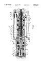
- FIG. 2 larger-scale section along line II--II in FIG. 1;
- FIG. 3 shows a partial view in perspective of a machine tool featuring a number of toolheads in accordance with the present invention.
- Numeral 1 in FIG. 1 indicates a chip-forming machine tool comprising a base 2; and a work table 3 connected in known manner to base 2, and movable in relation to base 2 by a known drive unit (not shown), so as to move a workpiece 4 in two horizontal, perpendicular directions 5 and 6.
- Machine tool 1 also comprises an upright pedestal 7 having a bottom end portion connected integrally with base 2, and a top end portion fitted with a fixed arm 8 supporting toolhead 9.
- toolhead 9 presents a vertical axis 10, and provides for supporting and moving, along axis 10, any one of a number of interchangeable tools 11 employed on machine tool 1.
- toolhead 9 comprises an elongated outer casing 12 connected integrally with arm 8 and presenting a first tubular portion 13 coaxial with axis 10 and closed at a first end by a wall 14, and a second tubular cylindrical portion 15 extending from a second end of portion 13 and coaxial with axis 10.
- Portion 15 defines a guide for a cylindrical sleeve 16 coaxial with axis 10 and connected in axially-sliding manner to portion 15 via the interposition of a liner 17 of antifriction material.
- liner 17 is replaced by a recirculating-ball bushing.
- Sleeve 16 is locked angularly in relation to casing 12 by means of an angular lock device 18 comprising a fixed guide rod 19 connected to portion 13 and parallel to axis 10; and a recirculating-ball bushing 20 connected integrally with the end portion of sleeve 16 facing wall 14, and connected in axially-sliding manner to rod 19.
- an angular lock device 18 comprising a fixed guide rod 19 connected to portion 13 and parallel to axis 10; and a recirculating-ball bushing 20 connected integrally with the end portion of sleeve 16 facing wall 14, and connected in axially-sliding manner to rod 19.
- spindle 21 for supporting tool 11.
- Spindle 21 extends coaxially with axis 10, and is connected to sleeve 16 in rotary, axially-fixed manner by means of four bearings 22 gripped against respective shoulders of sleeve 16 by a bushing 23 connected to sleeve 16 by a number of screws 24.
- spindle 21 is connected integrally with a hollow shaft 26 coaxial with axis 10 and connected to sleeve 16 by a pair of bearings 27, and is rotated about axis 10 by an electric motor 28 housed coaxially inside sleeve 16. More specifically, motor 28 is quill-drive type with its stator 29 secured integrally with the inner surface of sleeve 16 by a cylindrical casing 30, and its rotor 31 fitted to an intermediate portion of shaft 26.
- Spindle 21 presents a taper seat positively engaged by a known toolholder 32 for supporting tool 11 and which is retained inside the taper seat by a known releasable retaining device 33. More specifically, device 33 comprises a jaw 34 for positively engaging the shank of toolholder 32; and a control rod 35 connected to jaw 34, extending inside shaft 26, and loaded by a spring 36, also housed inside shaft 26, for maintaining jaw 34 closed when in use.
- toolhead 9 also comprises an actuating device 37 for moving sleeve 16 in relation to casing 12 and between a fully extracted and fully withdrawn position along axis 10.
- Actuating device 37 comprises a recirculating-ball drive 38 substantially inside sleeve 16 and coaxial with axis 10; and motor 39 for activating drive 38.
- Motor 39 is quill-drive type housed inside sleeve 16, with its stator 40 secured to the inner surface of sleeve 16 by casing 30.
- Motor 39 also presents a hollow rotor 41 fitted to a hollow supporting shaft 42 coaxial with axis 10 and connected to sleeve 16 in rotary, axially-fixed manner by means of a pair of bearings 43 on casing 30.
- Drive 38 comprises an externally threaded shaft 44 coaxial with axis 10, engaging in axially-sliding manner shaft 42 and at least part of shaft 26, and having an end portion connected integrally with wall 14, and an opposite end portion which, when sleeve 16 is close to the withdrawn position, contacts the end of and so defines an axial stop for rod 35.
- Drive 38 also comprises a nut 45 connected to shaft 44 via the interposition of a number of balls 46, and connected integrally with shaft 42 by means of a number of screws 47.
- toolhead 9 also comprises two position and angular speed transducers 48 and 49 for respectively controlling motors 28 and 39.
- Transducers 48 and 49 are housed inside sleeve 16, and present respective stators 50 secured integrally with the inner surface of sleeve 16 by casing 30, and respective rotors 51 fitted respectively to shafts 26 and 42.
- toolhead 9 comprises a pair of limit sensors 52 for determining said two limit positions of sleeve 16; and a further position sensor 53 for determining a zero position of sleeve 16.
- Sensors 52 and 53, transducers 48 and 49, and motors 28 and 39 are connected by respective wires A (only part of which is shown) and by a connector 54 to a known control system (not shown) for controlling and driving toolhead 9.
- toolhead 9 also comprises a unit for cooling the oil inside casing 12; and an electromagnetic brake, connected to shaft 42, for locking rotor 41 under given operating conditions.
- spindle 21 and, consequently, tool 11 are rotated about axis 10 by motor 28, and are controlled as to speed and angular position by the control system (not shown) as a function of the signals supplied to the control system by transducer 48.
- Axial displacement of spindle 21, on the other hand, is controlled by motor 39, which acts on sleeve 16 via drive 38, and is also controlled by the control system (not shown) as a function of the signals supplied to the control system by transducer 49.
- toolhead 9 By virtue of the internal configuration of toolhead 9, this is therefore extremely straightforward in design and considerably more compact and lightweight as compared with known toolheads. Furthermore, the internal configuration of toolhead 9 also provides for a high degree of reliability due mainly, though not exclusively, to the relatively small number of mutually sliding components involved.
- FIG. 3 shows a machine tool 58 differing slightly in design from machine tool 1 and the component parts of which are indicated, where possible, using the same numbering system.
- Machine tool 58 is a multispindle machine comprising, in place of table 3, a turret 59 supporting a number of workpieces 4, and rotated in steps in relation to the base (not shown) and about a substantially horizontal axis 60, for successively feeding workpieces 4 through a number of work stations 61.
- machine 58 comprises a number of variously-oriented toolheads 9, each positioned facing a respective workpiece 4 in a respective station 61, for performing a specific machining operation on workpiece 4.
- machine tool 58 comprises two or more toolheads 9 for performing different machining operations on workpiece 4 simultaneously.
Abstract
Description
Claims (16)
Applications Claiming Priority (2)
| Application Number | Priority Date | Filing Date | Title |
|---|---|---|---|
| ITPG920005A IT1261640B (en) | 1992-03-30 | 1992-03-30 | ELECTROMECHANICAL OPERATING UNIT HAVING BOTH ELECTRIC MOTORS AND THE RECIRCULATION SCREW OF COAXIAL BALLS WITH THE SPINDLE AND INSIDE THE MOBILE SPINDLE |
| ITPG92A0005 | 1992-03-30 |
Publications (1)
| Publication Number | Publication Date |
|---|---|
| US5350263A true US5350263A (en) | 1994-09-27 |
Family
ID=11393265
Family Applications (1)
| Application Number | Title | Priority Date | Filing Date |
|---|---|---|---|
| US08/038,525 Expired - Fee Related US5350263A (en) | 1992-03-30 | 1993-03-29 | Toolhead for chip-forming machine tools |
Country Status (6)
| Country | Link |
|---|---|
| US (1) | US5350263A (en) |
| EP (1) | EP0563862B1 (en) |
| JP (1) | JPH0740103A (en) |
| DE (1) | DE69312994T2 (en) |
| ES (1) | ES2104986T3 (en) |
| IT (1) | IT1261640B (en) |
Cited By (12)
| Publication number | Priority date | Publication date | Assignee | Title |
|---|---|---|---|---|
| US5791836A (en) * | 1993-09-13 | 1998-08-11 | Komet Praezisionswerkzeuge Robert Breuning Gmbh | Tool head with external current supply |
| US5997223A (en) * | 1998-09-22 | 1999-12-07 | Electro Scientific Industries, Inc. | High speed drilling spindle with reciprocating ceramic shaft and edoubl-gripping centrifugal chuck |
| US6036414A (en) * | 1996-02-22 | 2000-03-14 | Renault Automation | Electric spindle holder slide for a high-speed machine tool |
| US6600250B1 (en) * | 1999-11-23 | 2003-07-29 | Gifam S.R.L. | Machine tool |
| US20080232914A1 (en) * | 2007-03-23 | 2008-09-25 | The Boeing Company | Drill Spindles with Inline Direct Drive Feed |
| US7547169B1 (en) * | 2008-07-11 | 2009-06-16 | Zagar Inc. | Drilling module with automatic tool changer |
| US20090257836A1 (en) * | 2008-04-11 | 2009-10-15 | Dennis Mathis | Method and apparatus for a spindle with servo feed control |
| US20100303571A1 (en) * | 2007-05-15 | 2010-12-02 | Huller Hille Gmbh | Motor-Driven Working Spindle for a Machine Tool |
| WO2012012078A2 (en) * | 2010-07-23 | 2012-01-26 | Zagar Inc. | End effector |
| US20120138323A1 (en) * | 2009-08-07 | 2012-06-07 | The University Of Sheffield | Remote confined-space machining, and positioning and securing arrangement |
| US20130305869A1 (en) * | 2012-05-21 | 2013-11-21 | Rainer Krumbacher | Industrial robot with actuators extending in a primary hand enclosure |
| US20140328639A1 (en) * | 2013-05-02 | 2014-11-06 | Artis Gmbh | Adjusting Adjustable Tools Clamped on a Motor Spindle of a Machine Tool |
Families Citing this family (6)
| Publication number | Priority date | Publication date | Assignee | Title |
|---|---|---|---|---|
| IT1261335B (en) * | 1993-11-05 | 1996-05-14 | Pluritec Italia | OPERATING MACHINE FOR THE MECHANICAL PROCESSING OF PLATES, IN PARTICULAR FOR PRINTED CIRCUITS. |
| IT1261334B (en) * | 1993-11-05 | 1996-05-14 | Pluritec Italia | OPERATING HEAD FOR THE MECHANICAL PROCESSING OF PLATES, IN PARTICULAR OF PRINTED CIRCUITS. |
| FR2726213B1 (en) * | 1994-10-27 | 1996-12-20 | Gb Tronic | DRIVE MECHANISM OF A MACHINING SPINDLE |
| ITMI20081254A1 (en) * | 2008-07-10 | 2010-01-11 | Ficep Spa | Drive mechanism of the movable slide for an extrusion press |
| DE102010042281A1 (en) * | 2010-07-12 | 2012-01-12 | Index-Werke Gmbh & Co. Kg Hahn & Tessky | Spindles |
| DE102014109661B4 (en) * | 2014-07-10 | 2021-12-30 | Föhrenbach GmbH | High frequency drilling spindle |
Citations (6)
| Publication number | Priority date | Publication date | Assignee | Title |
|---|---|---|---|---|
| JPS62157745A (en) * | 1985-12-28 | 1987-07-13 | Sankyo Seiki Mfg Co Ltd | Spindle device with function of automatic tool replacement |
| DE3819181A1 (en) * | 1988-06-06 | 1989-12-07 | Wanderer Maschinen Gmbh | Milling and/or drilling machine with work-spindle locking |
| EP0362781A2 (en) * | 1988-10-07 | 1990-04-11 | Mca Micro Crystal Ag | High-frequency spindle for machining workpieces |
| US5009554A (en) * | 1989-09-09 | 1991-04-23 | Brother Kogyo Kabushiki Kaisha | Machine tool |
| JPH03251384A (en) * | 1990-02-28 | 1991-11-08 | Nitto Seiko Co Ltd | Working tool raising/lowering device and working tool rotatively driving device |
| US5100271A (en) * | 1988-03-28 | 1992-03-31 | Brother Kogyo Kabushiki Kaisha | Tool driving unit |
-
1992
- 1992-03-30 IT ITPG920005A patent/IT1261640B/en active IP Right Grant
-
1993
- 1993-03-29 US US08/038,525 patent/US5350263A/en not_active Expired - Fee Related
- 1993-03-29 EP EP93105192A patent/EP0563862B1/en not_active Expired - Lifetime
- 1993-03-29 ES ES93105192T patent/ES2104986T3/en not_active Expired - Lifetime
- 1993-03-29 DE DE69312994T patent/DE69312994T2/en not_active Expired - Fee Related
- 1993-03-30 JP JP5095352A patent/JPH0740103A/en active Pending
Patent Citations (6)
| Publication number | Priority date | Publication date | Assignee | Title |
|---|---|---|---|---|
| JPS62157745A (en) * | 1985-12-28 | 1987-07-13 | Sankyo Seiki Mfg Co Ltd | Spindle device with function of automatic tool replacement |
| US5100271A (en) * | 1988-03-28 | 1992-03-31 | Brother Kogyo Kabushiki Kaisha | Tool driving unit |
| DE3819181A1 (en) * | 1988-06-06 | 1989-12-07 | Wanderer Maschinen Gmbh | Milling and/or drilling machine with work-spindle locking |
| EP0362781A2 (en) * | 1988-10-07 | 1990-04-11 | Mca Micro Crystal Ag | High-frequency spindle for machining workpieces |
| US5009554A (en) * | 1989-09-09 | 1991-04-23 | Brother Kogyo Kabushiki Kaisha | Machine tool |
| JPH03251384A (en) * | 1990-02-28 | 1991-11-08 | Nitto Seiko Co Ltd | Working tool raising/lowering device and working tool rotatively driving device |
Cited By (22)
| Publication number | Priority date | Publication date | Assignee | Title |
|---|---|---|---|---|
| US5791836A (en) * | 1993-09-13 | 1998-08-11 | Komet Praezisionswerkzeuge Robert Breuning Gmbh | Tool head with external current supply |
| US6036414A (en) * | 1996-02-22 | 2000-03-14 | Renault Automation | Electric spindle holder slide for a high-speed machine tool |
| US5997223A (en) * | 1998-09-22 | 1999-12-07 | Electro Scientific Industries, Inc. | High speed drilling spindle with reciprocating ceramic shaft and edoubl-gripping centrifugal chuck |
| US6227777B1 (en) * | 1998-09-22 | 2001-05-08 | Electro Scientific Industries, Inc. | High speed drilling spindle with reciprocating shaft and double-gripping centrifugal chuck |
| US6600250B1 (en) * | 1999-11-23 | 2003-07-29 | Gifam S.R.L. | Machine tool |
| US7887268B2 (en) * | 2007-03-23 | 2011-02-15 | The Boeing Company | Drill spindles with inline direct drive feed |
| US20080232914A1 (en) * | 2007-03-23 | 2008-09-25 | The Boeing Company | Drill Spindles with Inline Direct Drive Feed |
| US8454283B2 (en) * | 2007-05-15 | 2013-06-04 | Mag Ias, Gmbh | Motor-driven working spindle for a machine tool |
| US20100303571A1 (en) * | 2007-05-15 | 2010-12-02 | Huller Hille Gmbh | Motor-Driven Working Spindle for a Machine Tool |
| US20090257836A1 (en) * | 2008-04-11 | 2009-10-15 | Dennis Mathis | Method and apparatus for a spindle with servo feed control |
| US8167518B2 (en) * | 2008-04-11 | 2012-05-01 | The Boeing Company | Method and apparatus for a spindle with servo feed control |
| US7547169B1 (en) * | 2008-07-11 | 2009-06-16 | Zagar Inc. | Drilling module with automatic tool changer |
| US8267188B2 (en) * | 2009-08-07 | 2012-09-18 | The University Of Sheffield | Remote confined-space machining, and positioning and securing arrangement |
| US20120138323A1 (en) * | 2009-08-07 | 2012-06-07 | The University Of Sheffield | Remote confined-space machining, and positioning and securing arrangement |
| WO2012012078A3 (en) * | 2010-07-23 | 2012-04-12 | Zagar Inc. | End effector |
| WO2012012078A2 (en) * | 2010-07-23 | 2012-01-26 | Zagar Inc. | End effector |
| US8926240B2 (en) | 2010-07-23 | 2015-01-06 | Zagar Inc. | End effector |
| US9308592B2 (en) | 2010-07-23 | 2016-04-12 | Zagar Inc. | End effector |
| US10058966B2 (en) | 2010-07-23 | 2018-08-28 | Zagar Inc. | End effector |
| US20130305869A1 (en) * | 2012-05-21 | 2013-11-21 | Rainer Krumbacher | Industrial robot with actuators extending in a primary hand enclosure |
| US9102065B2 (en) * | 2012-05-21 | 2015-08-11 | Kuka Roboter Gmbh | Industrial robot with actuators extending in a primary hand enclosure |
| US20140328639A1 (en) * | 2013-05-02 | 2014-11-06 | Artis Gmbh | Adjusting Adjustable Tools Clamped on a Motor Spindle of a Machine Tool |
Also Published As
| Publication number | Publication date |
|---|---|
| ES2104986T3 (en) | 1997-10-16 |
| DE69312994D1 (en) | 1997-09-18 |
| ITPG920005A1 (en) | 1993-09-30 |
| ITPG920005A0 (en) | 1992-03-30 |
| IT1261640B (en) | 1996-05-23 |
| JPH0740103A (en) | 1995-02-10 |
| DE69312994T2 (en) | 1997-12-18 |
| EP0563862A1 (en) | 1993-10-06 |
| EP0563862B1 (en) | 1997-08-13 |
Similar Documents
| Publication | Publication Date | Title |
|---|---|---|
| US5350263A (en) | Toolhead for chip-forming machine tools | |
| US5584621A (en) | Direct drive multiple axes rotary spindle head for milling machine | |
| EP2204258B1 (en) | Machine tool spindle head | |
| US20100183395A1 (en) | Orbital drilling tool unit | |
| JPH04250904A (en) | High speed boring rod or milling main shaft | |
| US20070099744A1 (en) | Planetary gear | |
| US6053082A (en) | Holder for orbitable tool | |
| US4856178A (en) | Machine tool for turning, milling, boring, drilling, and washing with independent means for clamping the part to be machined | |
| US6886225B2 (en) | Worktable for numerical control machine tools | |
| EP0537124B1 (en) | Portable boring machine | |
| EP0220359A2 (en) | Live tooling turret | |
| US4642861A (en) | Machine tool construction | |
| JPS61288907A (en) | Drilling robot | |
| KR101945209B1 (en) | Facing head for boring machine | |
| KR101485559B1 (en) | Verticality type numerically controlled lathe | |
| US4528876A (en) | Universal single spindle pin crankshaft lathe | |
| KR20090099272A (en) | Turret droop prevention device of tool post for cnc lathe | |
| KR102374067B1 (en) | Universal head units for machine tools | |
| KR100521862B1 (en) | A rotation tool apparotus of the tool stock | |
| KR102565088B1 (en) | Universal head unit for machine tools with speed control | |
| KR101913570B1 (en) | A Rotating Tool Having Compensation Structure of Clutch Shaft | |
| JPS6338970Y2 (en) | ||
| KR100246300B1 (en) | A vertical movable equipment of nc lathe | |
| SU1171286A1 (en) | Spindle head of metal-working machine tool | |
| JPS5828721Y2 (en) | Headstock sliding type numerically controlled compound lathe |
Legal Events
| Date | Code | Title | Description |
|---|---|---|---|
| AS | Assignment |
Owner name: GIFAM S.R.L., ITALY Free format text: ASSIGNMENT OF ASSIGNORS INTEREST;ASSIGNOR:GIFAM S.R.L.;REEL/FRAME:007036/0180 Effective date: 19940608 |
|
| AS | Assignment |
Owner name: GIFAM S.R.L., ITALY Free format text: CORRECTIVE ASSIGNMENT TO CORRECT THE NAME OF THE CONVEYING PARTY IN A DOCUMENT RECORDED AT REEL 7036 FRAME 180;ASSIGNOR:FEDELI, GIANCARLO;REEL/FRAME:007188/0281 Effective date: 19940608 |
|
| FPAY | Fee payment |
Year of fee payment: 4 |
|
| FPAY | Fee payment |
Year of fee payment: 8 |
|
| REMI | Maintenance fee reminder mailed | ||
| LAPS | Lapse for failure to pay maintenance fees | ||
| STCH | Information on status: patent discontinuation |
Free format text: PATENT EXPIRED DUE TO NONPAYMENT OF MAINTENANCE FEES UNDER 37 CFR 1.362 |
|
| FP | Lapsed due to failure to pay maintenance fee |
Effective date: 20060927 |