US5336357A - Manually operable die attach apparatus - Google Patents
Manually operable die attach apparatus Download PDFInfo
- Publication number
- US5336357A US5336357A US08/030,702 US3070293A US5336357A US 5336357 A US5336357 A US 5336357A US 3070293 A US3070293 A US 3070293A US 5336357 A US5336357 A US 5336357A
- Authority
- US
- United States
- Prior art keywords
- chip
- support
- substrate
- base
- arm
- Prior art date
- Legal status (The legal status is an assumption and is not a legal conclusion. Google has not performed a legal analysis and makes no representation as to the accuracy of the status listed.)
- Expired - Fee Related
Links
Images


Classifications
-
- H—ELECTRICITY
- H05—ELECTRIC TECHNIQUES NOT OTHERWISE PROVIDED FOR
- H05K—PRINTED CIRCUITS; CASINGS OR CONSTRUCTIONAL DETAILS OF ELECTRIC APPARATUS; MANUFACTURE OF ASSEMBLAGES OF ELECTRICAL COMPONENTS
- H05K13/00—Apparatus or processes specially adapted for manufacturing or adjusting assemblages of electric components
- H05K13/04—Mounting of components, e.g. of leadless components
- H05K13/046—Surface mounting
- H05K13/0465—Surface mounting by soldering
-
- H—ELECTRICITY
- H05—ELECTRIC TECHNIQUES NOT OTHERWISE PROVIDED FOR
- H05K—PRINTED CIRCUITS; CASINGS OR CONSTRUCTIONAL DETAILS OF ELECTRIC APPARATUS; MANUFACTURE OF ASSEMBLAGES OF ELECTRICAL COMPONENTS
- H05K13/00—Apparatus or processes specially adapted for manufacturing or adjusting assemblages of electric components
- H05K13/04—Mounting of components, e.g. of leadless components
- H05K13/0404—Pick-and-place heads or apparatus, e.g. with jaws
- H05K13/0408—Incorporating a pick-up tool
- H05K13/0409—Sucking devices
-
- H—ELECTRICITY
- H05—ELECTRIC TECHNIQUES NOT OTHERWISE PROVIDED FOR
- H05K—PRINTED CIRCUITS; CASINGS OR CONSTRUCTIONAL DETAILS OF ELECTRIC APPARATUS; MANUFACTURE OF ASSEMBLAGES OF ELECTRICAL COMPONENTS
- H05K13/00—Apparatus or processes specially adapted for manufacturing or adjusting assemblages of electric components
- H05K13/04—Mounting of components, e.g. of leadless components
- H05K13/0447—Hand tools therefor
-
- Y—GENERAL TAGGING OF NEW TECHNOLOGICAL DEVELOPMENTS; GENERAL TAGGING OF CROSS-SECTIONAL TECHNOLOGIES SPANNING OVER SEVERAL SECTIONS OF THE IPC; TECHNICAL SUBJECTS COVERED BY FORMER USPC CROSS-REFERENCE ART COLLECTIONS [XRACs] AND DIGESTS
- Y10—TECHNICAL SUBJECTS COVERED BY FORMER USPC
- Y10T—TECHNICAL SUBJECTS COVERED BY FORMER US CLASSIFICATION
- Y10T156/00—Adhesive bonding and miscellaneous chemical manufacture
- Y10T156/10—Methods of surface bonding and/or assembly therefor
- Y10T156/1089—Methods of surface bonding and/or assembly therefor of discrete laminae to single face of additional lamina
- Y10T156/1092—All laminae planar and face to face
-
- Y—GENERAL TAGGING OF NEW TECHNOLOGICAL DEVELOPMENTS; GENERAL TAGGING OF CROSS-SECTIONAL TECHNOLOGIES SPANNING OVER SEVERAL SECTIONS OF THE IPC; TECHNICAL SUBJECTS COVERED BY FORMER USPC CROSS-REFERENCE ART COLLECTIONS [XRACs] AND DIGESTS
- Y10—TECHNICAL SUBJECTS COVERED BY FORMER USPC
- Y10T—TECHNICAL SUBJECTS COVERED BY FORMER US CLASSIFICATION
- Y10T156/00—Adhesive bonding and miscellaneous chemical manufacture
- Y10T156/17—Surface bonding means and/or assemblymeans with work feeding or handling means
- Y10T156/1702—For plural parts or plural areas of single part
- Y10T156/1744—Means bringing discrete articles into assembled relationship
- Y10T156/1776—Means separating articles from bulk source
-
- Y—GENERAL TAGGING OF NEW TECHNOLOGICAL DEVELOPMENTS; GENERAL TAGGING OF CROSS-SECTIONAL TECHNOLOGIES SPANNING OVER SEVERAL SECTIONS OF THE IPC; TECHNICAL SUBJECTS COVERED BY FORMER USPC CROSS-REFERENCE ART COLLECTIONS [XRACs] AND DIGESTS
- Y10—TECHNICAL SUBJECTS COVERED BY FORMER USPC
- Y10T—TECHNICAL SUBJECTS COVERED BY FORMER US CLASSIFICATION
- Y10T156/00—Adhesive bonding and miscellaneous chemical manufacture
- Y10T156/17—Surface bonding means and/or assemblymeans with work feeding or handling means
- Y10T156/1798—Surface bonding means and/or assemblymeans with work feeding or handling means with liquid adhesive or adhesive activator applying means
-
- Y—GENERAL TAGGING OF NEW TECHNOLOGICAL DEVELOPMENTS; GENERAL TAGGING OF CROSS-SECTIONAL TECHNOLOGIES SPANNING OVER SEVERAL SECTIONS OF THE IPC; TECHNICAL SUBJECTS COVERED BY FORMER USPC CROSS-REFERENCE ART COLLECTIONS [XRACs] AND DIGESTS
- Y10—TECHNICAL SUBJECTS COVERED BY FORMER USPC
- Y10T—TECHNICAL SUBJECTS COVERED BY FORMER US CLASSIFICATION
- Y10T156/00—Adhesive bonding and miscellaneous chemical manufacture
- Y10T156/18—Surface bonding means and/or assembly means with handle or handgrip
-
- Y—GENERAL TAGGING OF NEW TECHNOLOGICAL DEVELOPMENTS; GENERAL TAGGING OF CROSS-SECTIONAL TECHNOLOGIES SPANNING OVER SEVERAL SECTIONS OF THE IPC; TECHNICAL SUBJECTS COVERED BY FORMER USPC CROSS-REFERENCE ART COLLECTIONS [XRACs] AND DIGESTS
- Y10—TECHNICAL SUBJECTS COVERED BY FORMER USPC
- Y10T—TECHNICAL SUBJECTS COVERED BY FORMER US CLASSIFICATION
- Y10T29/00—Metal working
- Y10T29/49—Method of mechanical manufacture
- Y10T29/49002—Electrical device making
- Y10T29/49117—Conductor or circuit manufacturing
- Y10T29/49124—On flat or curved insulated base, e.g., printed circuit, etc.
- Y10T29/4913—Assembling to base an electrical component, e.g., capacitor, etc.
- Y10T29/49144—Assembling to base an electrical component, e.g., capacitor, etc. by metal fusion
Definitions
- the present invention relates to the art of adhesive bonding of dies or chips to substrates, and more particularly to a manually operable apparatus for accurately placing the bonding paste and semiconductor chips on a substrate for the packaging of semiconductor devices.
- Adhesive pastes have been used in the semiconductor packaging industry for this purpose in a variety of applications.
- metallic-glass pastes have been used for attaching semiconductor chips to ceramic substrates in the manufacture of semiconductor devices, and particularly, large scale integrated (LSI) and very large scale (VLSI) circuits.
- LSI large scale integrated
- VLSI very large scale circuits.
- These circuits typically include a semiconductor chip or die, e.g., silicon, gallium arsenide, etc., which is bonded to a supporting ceramic substrate.
- Commonly assigned U.S. Pat. Nos. 4,636,254, 4,761,224 and 4,968,738 are directed to improved silver-glass die attach pastes for the attachment of a semiconductor die to a ceramic substrate.
- These patents disclose silver-glass die attach pastes consisting generally of a mixture of silver flake and glass frit distributed in an organic vehicle.
- the die be accurately placed on the substrate and that the bond is satisfactory.
- a selected quantity of the die attach paste is placed on the substrate and the die then placed on the paste.
- the die attach paste is thus positioned between the opposing die and substrate surfaces in a sandwiched relationship.
- the sample is dried and fired in a oven or furnace at temperatures above the glass transition temperature (T g ) of the glass constituent. During the drying and firing stages, the organic vehicle volatilizes and the glass flows to wet the ceramic substrate and die, while the silver flake sinters together. Upon cooling, the result is a secure bond between the die and the substrate.
- T g glass transition temperature
- the post-fired adhesive film must have an adequate and preferably uniform bond line thickness. If the bond line thickness is sufficient, the resultant bond will exhibit good resistance to differential thermal expansion rates between the die and substrate, and will produce a bond having a high tensile strength.
- Interfacial stress that arises from a thermal mismatch between the die and substrate is directly proportional to both the area of attachment and the modulus of elasticity of the bonding paste. This stress is also inversely proportional to the bond line thickness. Since the modulus of elasticity for a given die attach paste is fixed, the only avenue available to reduce interfacial stress is to maintain a sufficient bond line thickness on each part assembled. For the proper bonding of silicon die to ceramic substrates, the bond line thickness must be increased proportionally to the area of the surfaces to be bonded.
- metal-glass pastes It is a characteristic of metal-glass pastes that the paste collapses during drying and firing as the organic materials are eliminated from the composition. The amount of shrinkage varies from case to case. However, if a sufficiently large wet bond line thickness is initially maintained, post-fired bonds exhibiting suitable strength and thermal stress resistance characteristics may be obtained. This requires the accurate placement of paste and die to the substrate.
- a manually operable apparatus for the accurate and uniform mounting of chips to substrates includes a support structure having means for accurately placing a substrate for receiving an accurately placed and measured quantity of paste, and a swing assembly for selecting accurately positioned chips and precisely placing them on a prepositioned substrate.
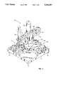
- FIG. 1 is a perspective view illustrating a preferred embodiment of the invention
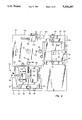
- FIG. 2 is a top plan view of the support base of the embodiment of FIG. 1;
- FIG. 3 is a side elevation view with portions broken away to show details of the swing arm assembly
- FIG. 4 is a detailed partial view cf a portion of the handgrip of FIG. 3;
- FIG. 5 is a top plan view of the swing arm assembly of FIG. 1;
- FIG. 6 is a plan view from the bottom of the support base.
- FIG. 7 is a view from the bottom of the dispensing head of FIG. 3.
- a manually operable chip assembly apparatus for selectively assembling chips to substrates is illustrated in a perspective view, and designated generally by the numeral 10.
- the apparatus comprises a generally square support base 12 supported on four adjustable leveling feet 14, one at each corner thereof.
- the base is generally formed of four quadrants, with a first adjustable support assembly, designated generally at 16, disposed in one quadrant for adjustably positioning and supporting a substrate preparatory to the attachment of a chip thereto.
- a second adjustable support, designated generally at 18, is disposed in a second quadrant of the support base diagonally across from the first support base, and for supporting a chip preparatory to selection for attachment to a substrate.
- These support structures each have course and fine XY adjustments for adjustably positioning a chip and substrate with a very high degree of accuracy.
- a manually operable swing arm assembly designated generally at 20, is mounted in a third quadrant of the support base for rotation about and vertically reciprocable movement on a support shaft 22.
- the swing arm assembly comprises a generally T-shaped structure having a central main body portion 24 and outwardly extending arms 26 and 28.
- a handle or handgrip 30 for manually grasping and manipulating the swing arm assembly is secured and extends axially upward therefrom.
- the swing arm assembly has a paste depositing syringe 32 mounted on one end of the extending arm 26 and a die pick up head 34 on the other extending arm 28 or opposite end of the arm assembly.
- the support base is formed of any suitable rigid material, such as metal or a good grade of rigid plastic with stable dimensions.
- the base support member is formed with a lower support table 36 in which the first adjustable support assembly 16 is mounted.
- the first adjustable support assembly 16 comprises a lower support carriage 38 supported in side rails 40 and 42 formed in the base support and retained therein by means of cap screws 44 and 46.
- Adjustable means including a screw and thread assembly 48, adjustably positions the lower support table 36 in the side rails 40 and 42 for movement along an X axis.
- An upper support table 50 is mounted on the lower support table in side rails 52 and 54 for adjustable movement therealong by means of a screw and thread assembly 56.
- the screw and thread assembly 56 adjustably positions the upper support table 50 along a Y axis relative to the lower table and the support base.
- Adjustable stops 51 and 53 are adjustable to fix the position of two sides of the substrate.
- a vacuum hold down is provided by means of a vacuum port 55 which acts on the underside of a substrate.
- the vacuum port is connected by vacuum line 128 (FIG. 6) to the vacuum source.
- the second adjustable support 18 is mounted in a quadrant 58 on side support rails 60 and 62 and adjustable therealong by means of a screw and thread assembly 64.
- the second adjustable support 18 includes a lower support table 66 slidably mounted in the support rails 60 and 62, and is similarly provided with support rails 68 and 70 in which an upper support table 72 is slidably mounted and adjustable by means of a screw and thread assembly 74.
- the upper support table 72 is moveable along the X axis on the lower support table 66 and is secured in adjusted position by means of a pair of cap screws 76.
- a chip or die 71 is positioned on the upper support table 72 by means of shoulders 73 and 75.
- the support base is provided with a stepped up area in a quadrant 78 in which the swing arm assembly 20 is mounted.
- a centrally located bore 80 receives and mounts the vertically extending stationary support shaft 22.
- a pair of alignment and guide bores 84 and 88 are provided for receiving guide pins and guiding the swing arm assembly along an X axis.
- a pair of clearance holes 82 and 86 receive the pins of the arm assembly for guiding and aligning the swing arm assembly along a Y axis.
- the swing arm assembly as best seen in FIG. 3, comprises a central main body portion 24 forming a hub having a central bore 90 in which is disposed suitable bearings, such as sleeve bearings 92, supporting the swing arm assembly for rotation and vertical movement on the support shaft 22.
- suitable bearings such as sleeve bearings 92
- a spring assembly including a compression coil spring 94, positioned over a pin 96 secured in the upper end of the support shaft 22 and extending through a bore 98 in the upper end of the swing arm, hub with a retaining washer assembly 100 thereon.
- the coil spring 94 bears against plastic wear washers 95 at its ends and acts to bias the swing arm to its uppermost position.
- An 0-ring 99 is positioned over the upper end of pin 96 and beneath washer 100.
- the extending arm 26 includes a clamp assembly with a clamp member 102 at the outer end thereof.
- the clamp member 102 has a semi-circular cut-out matched to one in the end of extending arm 26 forming a circular bore 104 within the outer end of the arm for receiving a die attach paste injector or syringe 32, as shown in FIGS. 1 and 3.
- the clamp member 102 is detachably secured to the end of the arm by suitable means, such as cap screws, not shown.
- the opposite end of the arm assembly, specifically extending arm 28, is provided with a suitable die pick up head 34 for gripping chips. Vacuum is applied to the die pick up head 34 supplied by means of vacuum line 130 connected at vacuum port 108 (FIG. 5).
- the arm assembly includes a pair of guide pins or fingers 110 and 112 extending downward from a lower extension thereof for engaging the respective alignment and guide bores 84 and 88 in the base (FIG. 2). These align and guide the arm assembly as it respectively deposits solder paste on the substrate, picks up a chip and deposits or positions it on the substrate.
- the arm assembly is similarly provided with a pair of stop members 106 and 114 adjacent the guide pins 110 and 112 for engaging the heads of stop bolts or pins 116 and 118 on the support base. The stops may be adjusted to precisely adjust the vertical positioning of the respective arms as they place the adhesive paste and pick up and place the chip on the substrate.
- a source of vacuum such as a vacuum pump 120
- a suitable line 122 is connected by a suitable line 122 to a connector port 124 for supplying vacuum by means of a manifold and a series of vacuum lines 126, 128 and 130 to the respective vacuum clamps and grips.
- the vacuum line 130 connects to vacuum port 108 on the swing arm assembly and opens or communicates via a line and a port 132 to the die pick up head 34.
- a vacuum line or passage communicates with bore or chamber 136 in handle or hand grip 30.
- a valve member 138 is mounted on a stem 140 in bore 142 and biased by a compression spring 144 to a closed position.
- the valve member 138 covers vent ports 146 in the closed position, so that the vacuum pick up head 124 is always active until vented by pressing on the upper end of stem 140.
- a chip or die is automatically picked up when contacted by die pick up head 34 and is released when die pick up head 34 is vented.
- An adjustable valve member 148 (FIG. 2) may be provided in the vacuum system to adjust the vacuum to the die pick up head 34 and to the hold down vacuum port 55.
- the die pick up head 34 is activated by the operator placing a thumb over and closing the port 132 in handle or hand grip 30. This activates the die pick up 34 to grip and pick up the chip or die to place it on the substrate. Thereafter, removing the thumb from the port 132 releases the chip as it is placed on the substrate.
- a paste dispensing head 150 for the paste syringe 32 is illustrated.
- the dispensing head has a face with a central port 152 for receiving paste from the barrel of the syringe, and channels 154, 156, 158 and 160 for distributing it outward over the face of the die.
- the face of the head is positioned in substantially close contact with the surface of the substrate and the paste dispensed.
- the paste flows out along the channels over the area of the surface of the substrate.
- a head such as that disclosed in U.S. Pat. No. 4,803,124, issued Feb. 7, 1989 to Kunz, may be used.
Landscapes
- Engineering & Computer Science (AREA)
- Manufacturing & Machinery (AREA)
- Microelectronics & Electronic Packaging (AREA)
- Die Bonding (AREA)
Abstract
Description
Claims (17)
Priority Applications (1)
| Application Number | Priority Date | Filing Date | Title |
|---|---|---|---|
| US08/030,702 US5336357A (en) | 1993-03-12 | 1993-03-12 | Manually operable die attach apparatus |
Applications Claiming Priority (1)
| Application Number | Priority Date | Filing Date | Title |
|---|---|---|---|
| US08/030,702 US5336357A (en) | 1993-03-12 | 1993-03-12 | Manually operable die attach apparatus |
Publications (1)
| Publication Number | Publication Date |
|---|---|
| US5336357A true US5336357A (en) | 1994-08-09 |
Family
ID=21855566
Family Applications (1)
| Application Number | Title | Priority Date | Filing Date |
|---|---|---|---|
| US08/030,702 Expired - Fee Related US5336357A (en) | 1993-03-12 | 1993-03-12 | Manually operable die attach apparatus |
Country Status (1)
| Country | Link |
|---|---|
| US (1) | US5336357A (en) |
Cited By (13)
| Publication number | Priority date | Publication date | Assignee | Title |
|---|---|---|---|---|
| US5639323A (en) * | 1995-02-17 | 1997-06-17 | Aiwa Research And Development, Inc. | Method for aligning miniature device components |
| US5814173A (en) * | 1996-07-31 | 1998-09-29 | Chrysler Corporation | Apparatus and method for positively locating and attaching an emblem on a vehicle |
| US5830297A (en) * | 1995-07-24 | 1998-11-03 | Matsushita Electric Industrial Co., Ltd. | Method and apparatus for application of adhesive |
| US5849141A (en) * | 1995-10-30 | 1998-12-15 | Kinematic Automation, Inc. | Method and apparatus for precision card lamination |
| US5882451A (en) * | 1996-03-27 | 1999-03-16 | Matsushita Electric Industrial Co., Ltd. | Method and apparatus for applying an electronic component adhesive |
| US5942083A (en) * | 1996-04-22 | 1999-08-24 | Sony Corporation | Manual Electronic-part mounting apparatus |
| US5951819A (en) * | 1996-09-16 | 1999-09-14 | Stomp, Inc. | Optical disc adhesive label applicator |
| US6206066B1 (en) * | 1995-12-15 | 2001-03-27 | Matsushita Electric Industrial Co., Ltd. | Apparatus for mounting an electronic component |
| US6387733B1 (en) | 2001-05-22 | 2002-05-14 | Rf Micro Devices, Inc. | Time-based semiconductor material attachment |
| US6517656B1 (en) * | 1999-10-05 | 2003-02-11 | Amkor Technology, Inc. | Method of making an integrated circuit package using a batch step for curing a die attachment film and a tool system for performing the method |
| US20110017133A1 (en) * | 2009-07-25 | 2011-01-27 | Yong Zheng | Automatic Dispensing Machine |
| DE102009034052A1 (en) * | 2009-07-21 | 2011-02-17 | Siemens Aktiengesellschaft | Component holding device for mounting machine, has adjusting element for changing position of multiple component carriers, where component carriers comprise thread drive and receiving element and are arranged parallel to each other |
| US20140182789A1 (en) * | 2012-12-27 | 2014-07-03 | Hon Hai Precision Industry Co., Ltd. | Bonding device |
Citations (11)
| Publication number | Priority date | Publication date | Assignee | Title |
|---|---|---|---|---|
| US3715258A (en) * | 1971-03-23 | 1973-02-06 | Bancroft H Corp | Integrated circuit die bonding apparatus |
| US3834966A (en) * | 1972-12-26 | 1974-09-10 | Mech El Inc Ind | Adhesive bonding system |
| US3855034A (en) * | 1973-12-10 | 1974-12-17 | C Miller | Method and apparatus for bonding in miniaturized electrical circuits |
| US4239576A (en) * | 1978-07-19 | 1980-12-16 | Matsushita Electric Industrial Co., Ltd. | Process for mounting electronic parts |
| JPS60177661A (en) * | 1984-02-23 | 1985-09-11 | Matsushita Electric Ind Co Ltd | Soldering method of semiconductor |
| US4636254A (en) * | 1985-07-23 | 1987-01-13 | Quantum Materials, Inc. | Silver-glass paste for attachment of silicon die to ceramic substrate |
| US4761224A (en) * | 1986-03-10 | 1988-08-02 | Quantum Materials Inc. | Silver-glass paste with poly-modal flake size distribution and quick dry vehicle |
| US4868979A (en) * | 1988-05-24 | 1989-09-26 | Taiyo Yuden Co., Ltd. | Method of and apparatus for mounting chips |
| US4951388A (en) * | 1988-06-21 | 1990-08-28 | Matsushita Electric Industrial Co., Ltd. | Method of mounting electronic components |
| US4968738A (en) * | 1989-04-06 | 1990-11-06 | Quantum Materials, Inc. | Silver-glass die attach paste with reduced resin |
| US5155903A (en) * | 1990-04-18 | 1992-10-20 | Matsushita Electric Industrial Co., Ltd. | Electrical component placing apparatus and placing method therefor |
-
1993
- 1993-03-12 US US08/030,702 patent/US5336357A/en not_active Expired - Fee Related
Patent Citations (11)
| Publication number | Priority date | Publication date | Assignee | Title |
|---|---|---|---|---|
| US3715258A (en) * | 1971-03-23 | 1973-02-06 | Bancroft H Corp | Integrated circuit die bonding apparatus |
| US3834966A (en) * | 1972-12-26 | 1974-09-10 | Mech El Inc Ind | Adhesive bonding system |
| US3855034A (en) * | 1973-12-10 | 1974-12-17 | C Miller | Method and apparatus for bonding in miniaturized electrical circuits |
| US4239576A (en) * | 1978-07-19 | 1980-12-16 | Matsushita Electric Industrial Co., Ltd. | Process for mounting electronic parts |
| JPS60177661A (en) * | 1984-02-23 | 1985-09-11 | Matsushita Electric Ind Co Ltd | Soldering method of semiconductor |
| US4636254A (en) * | 1985-07-23 | 1987-01-13 | Quantum Materials, Inc. | Silver-glass paste for attachment of silicon die to ceramic substrate |
| US4761224A (en) * | 1986-03-10 | 1988-08-02 | Quantum Materials Inc. | Silver-glass paste with poly-modal flake size distribution and quick dry vehicle |
| US4868979A (en) * | 1988-05-24 | 1989-09-26 | Taiyo Yuden Co., Ltd. | Method of and apparatus for mounting chips |
| US4951388A (en) * | 1988-06-21 | 1990-08-28 | Matsushita Electric Industrial Co., Ltd. | Method of mounting electronic components |
| US4968738A (en) * | 1989-04-06 | 1990-11-06 | Quantum Materials, Inc. | Silver-glass die attach paste with reduced resin |
| US5155903A (en) * | 1990-04-18 | 1992-10-20 | Matsushita Electric Industrial Co., Ltd. | Electrical component placing apparatus and placing method therefor |
Cited By (20)
| Publication number | Priority date | Publication date | Assignee | Title |
|---|---|---|---|---|
| US5639323A (en) * | 1995-02-17 | 1997-06-17 | Aiwa Research And Development, Inc. | Method for aligning miniature device components |
| US5830297A (en) * | 1995-07-24 | 1998-11-03 | Matsushita Electric Industrial Co., Ltd. | Method and apparatus for application of adhesive |
| US5938871A (en) * | 1995-07-24 | 1999-08-17 | Matsushita Electric Industrial Co., Ltd. | Method and apparatus for application of adhesive |
| US5849141A (en) * | 1995-10-30 | 1998-12-15 | Kinematic Automation, Inc. | Method and apparatus for precision card lamination |
| US6206066B1 (en) * | 1995-12-15 | 2001-03-27 | Matsushita Electric Industrial Co., Ltd. | Apparatus for mounting an electronic component |
| US6527905B1 (en) | 1995-12-15 | 2003-03-04 | Matsushita Electric Industrial Co., Ltd. | Method for mounting electronic components and apparatus and dispenser used in the method |
| US5882451A (en) * | 1996-03-27 | 1999-03-16 | Matsushita Electric Industrial Co., Ltd. | Method and apparatus for applying an electronic component adhesive |
| US6315024B1 (en) | 1996-04-22 | 2001-11-13 | Sony Corporation | Manual electronic-part mounting apparatus and method |
| US6153255A (en) * | 1996-04-22 | 2000-11-28 | Sony Corporation | Manual electronic-part mounting method |
| US5942083A (en) * | 1996-04-22 | 1999-08-24 | Sony Corporation | Manual Electronic-part mounting apparatus |
| CN1103644C (en) * | 1996-04-22 | 2003-03-26 | 索尼公司 | Manual electronic-part mounting apparatus and method |
| US5814173A (en) * | 1996-07-31 | 1998-09-29 | Chrysler Corporation | Apparatus and method for positively locating and attaching an emblem on a vehicle |
| US5951819A (en) * | 1996-09-16 | 1999-09-14 | Stomp, Inc. | Optical disc adhesive label applicator |
| US6517656B1 (en) * | 1999-10-05 | 2003-02-11 | Amkor Technology, Inc. | Method of making an integrated circuit package using a batch step for curing a die attachment film and a tool system for performing the method |
| US6387733B1 (en) | 2001-05-22 | 2002-05-14 | Rf Micro Devices, Inc. | Time-based semiconductor material attachment |
| DE102009034052A1 (en) * | 2009-07-21 | 2011-02-17 | Siemens Aktiengesellschaft | Component holding device for mounting machine, has adjusting element for changing position of multiple component carriers, where component carriers comprise thread drive and receiving element and are arranged parallel to each other |
| US20110017133A1 (en) * | 2009-07-25 | 2011-01-27 | Yong Zheng | Automatic Dispensing Machine |
| US8225739B2 (en) * | 2009-07-25 | 2012-07-24 | Cheng Uei Precision Industry Co., Ltd. | Automatic dispensing machine |
| US20140182789A1 (en) * | 2012-12-27 | 2014-07-03 | Hon Hai Precision Industry Co., Ltd. | Bonding device |
| US9397067B2 (en) * | 2012-12-27 | 2016-07-19 | Fu Ding Electronical Technology (Jiashan) Co., Ltd. | Bonding device |
Similar Documents
| Publication | Publication Date | Title |
|---|---|---|
| US5336357A (en) | Manually operable die attach apparatus | |
| TWI579935B (en) | A flip chip bonding device | |
| US7644853B2 (en) | Apparatus for attaching solder balls to BGA package utilizing a tool to pick and dip the solder ball in flux | |
| US4611397A (en) | Pick and place method and apparatus for handling electrical components | |
| US4954453A (en) | Method of producing an article comprising a multichip assembly | |
| US3452917A (en) | Bonding beam-leaded devices to substrates | |
| US6537400B1 (en) | Automated method of attaching flip chip devices to a substrate | |
| US20110287560A1 (en) | In-situ melt and reflow process for forming flip-chip interconnections and systems thereof | |
| EP0360846A1 (en) | Moving jaw reflow soldering head | |
| US6193143B1 (en) | Solder bump forming method and mounting apparatus and mounting method of solder ball | |
| US4632294A (en) | Process and apparatus for individual pin repair in a dense array of connector pins of an electronic packaging structure | |
| US4844325A (en) | Method and apparatus for die-bonding semiconductor chip bonding | |
| US3568307A (en) | Method of picking up and bonding semiconductor wafers to a carrier | |
| US6651866B2 (en) | Precision bond head for mounting semiconductor chips | |
| DE102013112143B4 (en) | Adjustable pickup head and method of adjusting a pickup head and clamp head and method of making a device | |
| US3834966A (en) | Adhesive bonding system | |
| US6703259B2 (en) | System and method for achieving planar alignment of a substrate during solder ball mounting for use in semiconductor fabrication | |
| US3855034A (en) | Method and apparatus for bonding in miniaturized electrical circuits | |
| JPH1022306A (en) | Die bonding equipment | |
| KR100529746B1 (en) | Automated brush fluxing system for application of controlled amount of flux to packages | |
| TW560235B (en) | Retractable vacuum tube for positioning electronic components on printed circuit boards | |
| JPS6224635A (en) | Flip chip bonder | |
| JPH0691348B2 (en) | Electronic component automatic mounting device | |
| US20120267423A1 (en) | Methods and Apparatus for Thin Die Processing | |
| CA2372551C (en) | Improved structure and method for testing bond strength and/or removing integrated circuit devices bonded to substrates |
Legal Events
| Date | Code | Title | Description |
|---|---|---|---|
| AS | Assignment |
Owner name: QUANTUM MATERIALS, INC., CALIFORNIA Free format text: ASSIGNMENT OF ASSIGNORS INTEREST.;ASSIGNORS:LAYHER, FRANCIS W.;SUTTER, FRANCIS A.;REEL/FRAME:006490/0264;SIGNING DATES FROM 19930310 TO 19930320 |
|
| REFU | Refund |
Free format text: REFUND - PAYMENT OF MAINTENANCE FEE, 4TH YR, SMALL ENTITY (ORIGINAL EVENT CODE: R283); ENTITY STATUS OF PATENT OWNER: LARGE ENTITY Free format text: REFUND - 3.5 YR SURCHARGE - LATE PMT W/IN 6 MO, SMALL ENTITY (ORIGINAL EVENT CODE: R286); ENTITY STATUS OF PATENT OWNER: LARGE ENTITY |
|
| FEPP | Fee payment procedure |
Free format text: PAT HLDR NO LONGER CLAIMS SMALL ENT STAT AS SMALL BUSINESS (ORIGINAL EVENT CODE: LSM2); ENTITY STATUS OF PATENT OWNER: LARGE ENTITY |
|
| FPAY | Fee payment |
Year of fee payment: 4 |
|
| SULP | Surcharge for late payment | ||
| FEPP | Fee payment procedure |
Free format text: PAYOR NUMBER ASSIGNED (ORIGINAL EVENT CODE: ASPN); ENTITY STATUS OF PATENT OWNER: LARGE ENTITY |
|
| FEPP | Fee payment procedure |
Free format text: PAYER NUMBER DE-ASSIGNED (ORIGINAL EVENT CODE: RMPN); ENTITY STATUS OF PATENT OWNER: LARGE ENTITY Free format text: PAYOR NUMBER ASSIGNED (ORIGINAL EVENT CODE: ASPN); ENTITY STATUS OF PATENT OWNER: LARGE ENTITY |
|
| AS | Assignment |
Owner name: DEXTER CORPORATION, THE, CONNECTICUT Free format text: ASSIGNMENT OF ASSIGNORS INTEREST;ASSIGNOR:QUANTUM MATERIALS, INC.;REEL/FRAME:011379/0866 Effective date: 19971009 |
|
| AS | Assignment |
Owner name: DEXTER CORPORATION, CONNECTICUT Free format text: CHANGE OF NAME;ASSIGNOR:DEXTER CORPORATION, THE;REEL/FRAME:011400/0990 Effective date: 19980423 |
|
| AS | Assignment |
Owner name: LOCTITE CORPORATION, CONNECTICUT Free format text: ASSIGNMENT OF ASSIGNORS INTEREST;ASSIGNOR:DEXTER CORPORATION;REEL/FRAME:012350/0418 Effective date: 20010823 |
|
| FPAY | Fee payment |
Year of fee payment: 8 |
|
| REMI | Maintenance fee reminder mailed | ||
| REMI | Maintenance fee reminder mailed | ||
| LAPS | Lapse for failure to pay maintenance fees | ||
| STCH | Information on status: patent discontinuation |
Free format text: PATENT EXPIRED DUE TO NONPAYMENT OF MAINTENANCE FEES UNDER 37 CFR 1.362 |
|
| FP | Lapsed due to failure to pay maintenance fee |
Effective date: 20060809 |