US532068A - Middlings-purifier - Google Patents
Middlings-purifier Download PDFInfo
- Publication number
- US532068A US532068A US532068DA US532068A US 532068 A US532068 A US 532068A US 532068D A US532068D A US 532068DA US 532068 A US532068 A US 532068A
- Authority
- US
- United States
- Prior art keywords
- purifier
- brush
- bar
- plate
- shaft
- Prior art date
- Legal status (The legal status is an assumption and is not a legal conclusion. Google has not performed a legal analysis and makes no representation as to the accuracy of the status listed.)
- Expired - Lifetime
Links
- 238000010276 construction Methods 0.000 description 8
- 230000000875 corresponding Effects 0.000 description 8
- 239000004744 fabric Substances 0.000 description 6
- 238000005266 casting Methods 0.000 description 4
- XEEYBQQBJWHFJM-UHFFFAOYSA-N iron Chemical compound [Fe] XEEYBQQBJWHFJM-UHFFFAOYSA-N 0.000 description 4
- 230000000284 resting Effects 0.000 description 4
- 241000497429 Obus Species 0.000 description 2
- 210000003813 Thumb Anatomy 0.000 description 2
- 230000035508 accumulation Effects 0.000 description 2
- 239000000428 dust Substances 0.000 description 2
- 229910052742 iron Inorganic materials 0.000 description 2
- 238000003801 milling Methods 0.000 description 2
- 238000000746 purification Methods 0.000 description 2
- 230000036633 rest Effects 0.000 description 2
- 238000007665 sagging Methods 0.000 description 2
- 238000000926 separation method Methods 0.000 description 2
Images
Classifications
-
- B—PERFORMING OPERATIONS; TRANSPORTING
- B07—SEPARATING SOLIDS FROM SOLIDS; SORTING
- B07B—SEPARATING SOLIDS FROM SOLIDS BY SIEVING, SCREENING, SIFTING OR BY USING GAS CURRENTS; SEPARATING BY OTHER DRY METHODS APPLICABLE TO BULK MATERIAL, e.g. LOOSE ARTICLES FIT TO BE HANDLED LIKE BULK MATERIAL
- B07B1/00—Sieving, screening, sifting, or sorting solid materials using networks, gratings, grids, or the like
- B07B1/46—Constructional details of screens in general; Cleaning or heating of screens
- B07B1/50—Cleaning
- B07B1/52—Cleaning with brushes or scrapers
- B07B1/522—Cleaning with brushes or scrapers with brushes
Definitions
- My lnvention has relation to improvements in mlddlmgs purifiers and consists in the novel arrangement and combination of parts,
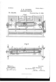
- Figure 1 is a side eleva. tion of my complete invention with parts broken away.
- Fig. 2 is a middle longitudinal vertical section of the same.
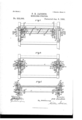
- Fig. 3 is a transverse section taken on the line t-Lt of Fig. 1.
- Fig. 4 is a section taken on the line bb of Fig. 1.
- Fig. 5 is a section on the line cc of Fig. 1.
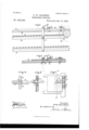
- Fig. 6 is a detailin side elevation showing the yielding end of the rack bar.
- Fig. 7 is a vertical mid-section through the rack bar.
- Fig. 8 is a side detail elevation of the means for adjusting the bearings of the shaft carrying the endless sprocket chain at' one end of the purifier.
- Fig. 9 is a section on the line d-dof Fig. 8; and
- Fig. 10 is a detail plan view of the bearings for the shaft at the opposite end of the machine.
- the object of my invention is to construct a middlings purifier which will greatly facilitate the separation of the specks and bran from the middlings proper; one wherein the meshes of the bolting cloth or sieve areat all times kept clear for the passage of the middlings; one wherein the brush acting on the under surface of the sieve ejects any dust which otherwise would have a tendency to clog the bristles and thus destroy the efficacy of the brush; one wherein the angle of the sieve and of the path of the brush co-operating therewith can be easily adjusted according to the variable conditions arising in mills, and one wherein the main bearings are adjustable from and located on the exterior of the apparatus, so that they can be oiled without 0pening the purifier andadmitting outside air thereinto, it being of course essential that the purifier be kept air tight at all times.
- 1 represents an ordinary purifier on the side of one end of which is mounted a drive shaft 2 having a belt wheel 3 over which passes a belt 4 to a pulley 5 on the shaft 6 of which operates an eccentric 7 which reciprocates the bolting cloth frame or sieve 8 loosely depending from the adjustable arms 9 depending from the sides of the purifier.
- each shaft 11 At either end of the purifier and passing through suitable enlarged openings 10 is a shaft 11, the outer projecting ends of each shaft being mountedeach in a bearing at one end of a supporting bar 12.
- the free end of eachbar 12 at one end of the purifier only has a slot 13 (there being no slotnecessaryon the corresponding bar at the opposite end as will be hereinafter explained) through which passes a bolt 14 which secures said bar'firmly to the outer wall of a transverse plate 15.
- the transverse plate 15 has slots 16 through which pass bolts 17 for securing it to the side of the purifier.
- the supporting bar is adjustable up and down and longitudinally, so that the distance between the shafts 11 can be varied and their relative elevations altered, thus varying the inclination of the sprocket chains connecting This is an old and well the two shafts, and thus varying the slack of th'e'chains when necessary.
- For a longitudinal adjustment it is obvious of course that it is sufficient to provide the bars 12 with slots 13 only at one end of the machine, the corresponding bars at the other end not having slots as is clear by a comparison of Figs. 8 and 10.
- each bar has a projecting perforated lug 26 (see Fig.5) into which loosely passes one end of a revoluble screw-threaded bolt 27, the outer portion of the bolt passing through an iron plate or casting 28 resting against the cross plate 15.
- the bolt has a thumb nut 29 which when turned in one direction or the other will adjust the bar 12 in either direction,it being understood of course that the bolt 14 is first loosened so that the bar 12 can slide freely.
- On each side of the center of each shaft 11 is a sprocket wheel 18 over which passes the sprocket chain 19 connecting the two shafts.
- the outer end of one of the shafts carries a sprocket wheel 20 connected by a chain 21 to a small sprocket wheel 21 mounted on the shaft 2.
- one of the links of each chain is a shaft 23 carrying a helical brush 24.
- a pinion 25 which serves to rotate the shaft 23 as it travels with the chains 19,by co-operating mechanism now to be described.
- the blocks are kept in any desirableposition by means of the stationary tightening bolt 32 passing outwardly through the slot 31 in the wall of the purifier, the outside of the slot being covered by a plate 33 through which the bolt 32 passes, and against which the rotating tightening nut 34 can be screwed, the said nut being provided with an operating handle or bar 35 and a suitable washer 36 being interposed between the nut and the plate 33.
- the object of this small adjustment is for the following purpose: It'was stated” above that the endless sprocket chains 19 carried the brushshaft 23 around the terminal sprocket wheels 18, the said brush shaft carrying the brush 24 alternately above'and below the said wheels. As the brush is returned to its position above the wheels 18 as indicated in Fig. 3, the pinion 25 engages with the rack bar 39, thus revolving the brush shaft and consequently the helical or spiral brush 24 secured thereto. While thus revolving, the shaft is guided in its forward movement by the antifriction rollers 47 mounted on the shaft 23 and coming between the guide rails 40-and the adj ustable rails 44.
- the rails 44 are therefore made slightly vertically adjustable to insure the positive meshing between the pinion 25 and rack bar 39, and prevent any lostmotion.
- the lower rails 41 are not absolutely necessary though they serve to stiffen and add strength to the parts.
- each is supported or connected along its medial portion with the rack bar 39 and rails 40 by an angle bar 48 similar to plates 37, the movable rail 44 being adjustably secured to this bar 48 in a manner similar to that by which it is secured to the plates 37.
- the rackbar rests on top of one guide rail 40, the rack portion depending on one side thereof.
- the extension 49 (see Fig. 6) of the rack bar is made slightly inclined along the rack portion thereof, and is yieldingly connected to the guide rail by the bolts 50 having the coiled springs 51 interposed between the top of the rack bar extension and the head 52 of each bolt.
- the bolts 50 pass through slots 53 of the rack bar extension thus allowing the extension to move and yield longitudinally at the moment the pinion 25 comes in engagement with it, the said extension being restored to its normal position by the spring yoke 54 having one end secured by the bolt 55 to the rigid portion of the rack bar and guide rail, and the opposite end being free to operate within a depression 56 formed in the guide rail, and having a horizontal projecting arm 57 on which the adjacent end of the extension 49 IIO may rest, the horizontal or flanged portion of therack bar being suitably cut away to accommodate the projecting arm 57. It will thus be apparent that the extension is yielding both in a vertical and horizontal direction, and all the jar is thus taken up. Of course as the pinion 25 leaves the rack barto pass below the sprocket wheels 18, no such arrangement is necessary.
- a vertical bevel strip 58 forming a bevel guide within which is free to move vertically a plate 59 havinga longitudinal slot 60.
- the rear of the plate 59 has a depression at right angles to the strips 58 the walls 61 of which act as a guide for a second plate 62 which it permits to move horizontally (that is, parallel to the slot within the depression, the said plate 62 having a circular opening 63 for the passage and support of the shaft 11.
- the respective plates are large enough to overlap the opening 10 and from the construction shown it is apparent that the plate 59 (with its horizontal slot) will allow a vertical adjustment of the shaft 11, and the plate 62 will allow of a horizontal adjustment moving only as it does parallel to the longitudinal slot of the plate 59, and yet at all times keep the opening 10 closed air tight.
- the operation is apparent from the description.
- the bolting frame 8 with its sieve is suspended at a proper angle for the reception of the middlings, and is then reciprocated rapidly by the machinery already described.
- the sprocket chains carrying the helical brush 24: are carried about their sprocket wheels as indicated by the arrows in Fig. 2,
- the brush revolving while in contact with the under surface of the sieve by the action of the pinion 25 meshing with the rack bar 39. If the pinion of the brush is not sufficiently in gear with the rack bar it may be adjusted by properly moving the adjustable rail 44 as already described. (See Fig. 4.) If the rack bar and guide rails are not at the proper angle of inclination to correspond with the pitch of the bolting cloth they may be adjusted in a manner already described. If the chains 19 are too slack they may be tightened by operating the bolts 27 (see Fig. 5) and thus in this way all parts can be accurately ada j usted from the outside of the machine, leaving the purifier air tight during the entire time the purification is going on.
- Fig. 1 it will be seen that the supporting bars 12 are only susceptible of horizontal adjustment at one end of the machine, so that what corresponds to plate 62 (see Fig. 5) is absent at the opposite end and a plate 59 moving vertically only, suffices for the vertical adjustment at the opposite end, in which case instead of an enlarged opening 10, a vertical slot 10 suffices for the vertical adjustment. (See Figs. 8 and 9.)
- a middlings purifier suitable traveling endless chains, a revolving spiral brush mounted transversely on the same, a pinion carried by the brush at one end, a rack bar co-operating with the pinion for rotating the brush in one position of its travel, suitable guide rails at either end of the brush shaft, adjustable railsin proximity to the guide rails, and suitable anti-friction rollers mounted on the brush shaft and running between the ,guide rails and the adjustable rails, substantially as set forth.
- a middlings purifier having openings alongits opposite walls, chain-carrying shafts passing through said openings and extending beyond the outer walls of the purifier, a Vertically moving plate having a horizontal slot embracing each shaft at either end, the said plate being located along the inside of the wall opposite the opening, a depression on the inner side of said plate forminga guide, a horizontally moving plate in said guide having an opening embracing theshaft, whereby the shafts may be adjusted vertically or horizontally without laying open the openings through which the ends of the shafts pass, substantially as set forth.
- a middlings purifier In a middlings purifier a series of vertically disposed plates, guide rails at the top of the same, bottom rails at the opposite ends thereof, and adjustable rails in proximity to the guide rails, substantially as set forth.
- a suitable block located along the inner wall of the purifier, a
- a suitable vertically adjustable block located along the inner wall of the purifier, a depression on the inner face of the said block, a vertical plate Secured to said block and having a vertical slot,a screw passing through said slot and into said depression, a suitable nut in the depression embracing the inner end of the screw, and a rail secured by the screw to the vertical plate whereby the rail is made vertically adjustable.
- a suitable guide rail a rack bar for the same, a suitable extension for said rackbar,spring-operated bolts securing the extension to the guide rail, horizontal slots in the extension through which the bolts pass, a spring yoke having its fixed end secured to the rack bar, and its free end co-operating with the extension whereby the latter has a yielding horizontal and vertical movement, and a brush adapted to travel on said-bar substantially as set forth.
- a middlings purifier suitable guide rails, a rack bar on said rails, a yielding extension for said rack bar, a brush adapted to travel on said bar, and means for actuating the brush, substantially as set forth.
Landscapes
- Brushes (AREA)
Description
(No Model.) 3 Sheets-Sheet 1.
- w I P. H. JAC'OBUS.
MIDDLINGS PURIFIER.
No. 532,068. I v Patented Jan. 8, 1895.
w itwaoaao 1117f Jacob 1w.
UNITED STATES PATENT OFFICE.
' PETER HENRY JACOBUS, OF MILLSTADT, ILLINOIS.
MlDDLlNGS-PURIFIER.
SPECIFICATION forming part of Letters Patent No. 532,068, dated January 8, 1895.
application filed July 9,1894.
scription, reference being had to the accompanying drawings, forming a part hereof.
My lnvention has relation to improvements in mlddlmgs purifiers and consists in the novel arrangement and combination of parts,
more fully set forth in the specification and pointed out in the claims.
In the drawings, Figure 1 is a side eleva. tion of my complete invention with parts broken away. Fig. 2 is a middle longitudinal vertical section of the same. Fig. 3 is a transverse section taken on the line t-Lt of Fig. 1. Fig. 4 is a section taken on the line bb of Fig. 1. Fig. 5 is a section on the line cc of Fig. 1. Fig. 6 is a detailin side elevation showing the yielding end of the rack bar. Fig. 7 is a vertical mid-section through the rack bar. Fig. 8 is a side detail elevation of the means for adjusting the bearings of the shaft carrying the endless sprocket chain at' one end of the purifier. Fig. 9 is a section on the line d-dof Fig. 8; and Fig. 10 is a detail plan view of the bearings for the shaft at the opposite end of the machine.
The object of my invention is to construct a middlings purifier which will greatly facilitate the separation of the specks and bran from the middlings proper; one wherein the meshes of the bolting cloth or sieve areat all times kept clear for the passage of the middlings; one wherein the brush acting on the under surface of the sieve ejects any dust which otherwise would have a tendency to clog the bristles and thus destroy the efficacy of the brush; one wherein the angle of the sieve and of the path of the brush co-operating therewith can be easily adjusted according to the variable conditions arising in mills, and one wherein the main bearings are adjustable from and located on the exterior of the apparatus, so that they can be oiled without 0pening the purifier andadmitting outside air thereinto, it being of course essential that the purifier be kept air tight at all times.
No claim is made to the construction of air chambers, bolting cloths, location of fans,
Serial No. 516,917. (No model.)
&c., the invention being limited to the particular arrangement and mode of travel of the helical brush co-operating with the bottom of the sieve, to the parts cooperating with said brush and to the various details now to be described.
Referring to the drawings, 1 represents an ordinary purifier on the side of one end of which is mounted a drive shaft 2 having a belt wheel 3 over which passes a belt 4 to a pulley 5 on the shaft 6 of which operates an eccentric 7 which reciprocates the bolting cloth frame or sieve 8 loosely depending from the adjustable arms 9 depending from the sides of the purifier. known construction and no further details of description are required.
At either end of the purifier and passing through suitable enlarged openings 10 is a shaft 11, the outer projecting ends of each shaft being mountedeach in a bearing at one end of a supporting bar 12. The free end of eachbar 12 at one end of the purifier only has a slot 13 (there being no slotnecessaryon the corresponding bar at the opposite end as will be hereinafter explained) through which passes a bolt 14 which secures said bar'firmly to the outer wall of a transverse plate 15. The transverse plate 15 has slots 16 through which pass bolts 17 for securing it to the side of the purifier. By the arrangement just described the supporting bar is adjustable up and down and longitudinally, so that the distance between the shafts 11 can be varied and their relative elevations altered, thus varying the inclination of the sprocket chains connecting This is an old and well the two shafts, and thus varying the slack of th'e'chains when necessary. For a longitudinal adjustment it is obvious of course that it is sufficient to provide the bars 12 with slots 13 only at one end of the machine, the corresponding bars at the other end not having slots as is clear by a comparison of Figs. 8 and 10.
To adjust the bars 12 to and from each other I employ the following mechanism: The inner face of each barhas a projecting perforated lug 26 (see Fig.5) into which loosely passes one end of a revoluble screw-threaded bolt 27, the outer portion of the bolt passing through an iron plate or casting 28 resting against the cross plate 15. The bolt has a thumb nut 29 which when turned in one direction or the other will adjust the bar 12 in either direction,it being understood of course that the bolt 14 is first loosened so that the bar 12 can slide freely. On each side of the center of each shaft 11 is a sprocket wheel 18 over which passes the sprocket chain 19 connecting the two shafts. The outer end of one of the shafts carries a sprocket wheel 20 connected by a chain 21 to a small sprocket wheel 21 mounted on the shaft 2. By this connection of parts the sprocket chains 19 are revolved.
one of the links of each chain is a shaft 23 carrying a helical brush 24. To one end of the shaft 23 is secured a pinion 25 which serves to rotate the shaft 23 as it travels with the chains 19,by co-operating mechanism now to be described. Along the inner side walls of the purifier, and at a convenient distance from the openings 10, are vertically adjustable blocks made so by reason of the slots 31, the blocks being kept in any desirableposition by means of the stationary tightening bolt 32 passing outwardly through the slot 31 in the wall of the purifier, the outside of the slot being covered by a plate 33 through which the bolt 32 passes, and against which the rotating tightening nut 34 can be screwed, the said nut being provided with an operating handle or bar 35 and a suitable washer 36 being interposed between the nut and the plate 33. To the inner faces of the blocks 30 are secured vertical plates 37 of suitable length there be ing disposed between the pair on one side of the purifier and secured to thelower surface of their right angled projecting arms 38 a rack bar 39 and an adjacent guide rail 40. The pair of plates on the opposite side of the machine however has only a corresponding rail 40 as best seen in Fig. 4, there being no rack bar on that side and consequently no necessity of the projecting arms 38. The lower portions of the respective pairs of plates 37 have secured thereto bottom rails 41. The plates 37 are each ,provided with vertical slots 42 located opposite corresponding de pressions 43 in the blocks 30. Located in proximity to the guide rails 40 are vertically adjustable rails 44, they being so adjustable by reason of being secured to the plates 37 by the screws 45 passing through said rails and through the slots 42, the inner end of the screws passing through a nut 46 confined Within the depression 43. It is apparent from this construction that if the rails 44 are desired to be adjusted to or from the guide rails 40, a slight loosening of the screw 45 will permit the rail to be moved vertically in either direction, and when once adjusted can be firmly secured in place by the same screw. The object of this small adjustment is for the following purpose: It'was stated" above that the endless sprocket chains 19 carried the brushshaft 23 around the terminal sprocket wheels 18, the said brush shaft carrying the brush 24 alternately above'and below the said wheels. As the brush is returned to its position above the wheels 18 as indicated in Fig. 3, the pinion 25 engages with the rack bar 39, thus revolving the brush shaft and consequently the helical or spiral brush 24 secured thereto. While thus revolving, the shaft is guided in its forward movement by the antifriction rollers 47 mounted on the shaft 23 and coming between the guide rails 40-and the adj ustable rails 44. The rails 44 are therefore made slightly vertically adjustable to insure the positive meshing between the pinion 25 and rack bar 39, and prevent any lostmotion. The lower rails 41 are not absolutely necessary though they serve to stiffen and add strength to the parts. To prevent the lower rails 41 from sagging along the middle of theirlength, each is supported or connected along its medial portion with the rack bar 39 and rails 40 by an angle bar 48 similar to plates 37, the movable rail 44 being adjustably secured to this bar 48 in a manner similar to that by which it is secured to the plates 37.
As the chains 1 9 revolve about the sprocket wheels 18, they carry the brush with them, and as the brush is thus carried along it will revolve with the shaft 23 so long as the pinion 25 is in engagement with the rack bar 39. This happens of course only while the brush is being carried above the sprocket wheels 18, that is to say, during the time the brush is in contact with the reciprocating sieve, the brush making no revolutions while it is passing below the sprocket wheels 18. As the pinion 25 comes successively in engagement with the rack bar 39 some provision should be made for taking up the jar incidentto such successive engagement between a rack and pinion. I have accordingly made that end of the rack bar which comes in successive engagement with the pinion on its return upward movement, yielding and slightly inclined along its lower surface as best seen in Fig. 6.
As seen from Figs. 4, 6, and 7, the rackbar rests on top of one guide rail 40, the rack portion depending on one side thereof. The extension 49 (see Fig. 6) of the rack bar is made slightly inclined along the rack portion thereof, and is yieldingly connected to the guide rail by the bolts 50 having the coiled springs 51 interposed between the top of the rack bar extension and the head 52 of each bolt. The bolts 50 pass through slots 53 of the rack bar extension thus allowing the extension to move and yield longitudinally at the moment the pinion 25 comes in engagement with it, the said extension being restored to its normal position by the spring yoke 54 having one end secured by the bolt 55 to the rigid portion of the rack bar and guide rail, and the opposite end being free to operate within a depression 56 formed in the guide rail, and having a horizontal projecting arm 57 on which the adjacent end of the extension 49 IIO may rest, the horizontal or flanged portion of therack bar being suitably cut away to accommodate the projecting arm 57. It will thus be apparent that the extension is yielding both in a vertical and horizontal direction, and all the jar is thus taken up. Of course as the pinion 25 leaves the rack barto pass below the sprocket wheels 18, no such arrangement is necessary.
It has already been stated, and best illustrated in Figs. 1 and 5, how the shafts 11 carried by the supporting bars 12 can be made adjustable to and from each other, and how they can be adjusted vertically. It was stated that the said shafts extend outwardly through the openings 10 formed in the sides of the purifier; but while these adjustments of the shafts 11' are being made'(and in fact at all times) it is necessary that the purifier be kept air tight.
To keep the openings 10 closed and at'the same time permit ofthe adjustments referred to, I have made the following provision: Referring particularly to Fig. 5, on either side of the opening 10 is secured a vertical bevel strip 58 forming a bevel guide within which is free to move vertically a plate 59 havinga longitudinal slot 60. The rear of the plate 59 has a depression at right angles to the strips 58 the walls 61 of which act as a guide for a second plate 62 which it permits to move horizontally (that is, parallel to the slot within the depression, the said plate 62 having a circular opening 63 for the passage and support of the shaft 11. The respective plates are large enough to overlap the opening 10 and from the construction shown it is apparent that the plate 59 (with its horizontal slot) will allow a vertical adjustment of the shaft 11, and the plate 62 will allow of a horizontal adjustment moving only as it does parallel to the longitudinal slot of the plate 59, and yet at all times keep the opening 10 closed air tight.
The operationis apparent from the description. The bolting frame 8 with its sieve is suspended at a proper angle for the reception of the middlings, and is then reciprocated rapidly by the machinery already described. The sprocket chains carrying the helical brush 24: are carried about their sprocket wheels as indicated by the arrows in Fig. 2,
' the brush revolving while in contact with the under surface of the sieve by the action of the pinion 25 meshing with the rack bar 39. If the pinion of the brush is not sufficiently in gear with the rack bar it may be adjusted by properly moving the adjustable rail 44 as already described. (See Fig. 4.) If the rack bar and guide rails are not at the proper angle of inclination to correspond with the pitch of the bolting cloth they may be adjusted in a manner already described. If the chains 19 are too slack they may be tightened by operating the bolts 27 (see Fig. 5) and thus in this way all parts can be accurately ada j usted from the outside of the machine, leaving the purifier air tight during the entire time the purification is going on. The brush being spiral, of course new parts of the brush are continuously brought in contact with the under surface of the sieve and thus the latter is kept clean, and for the same reasonthe brush itself will throw off all accumulations that may lodge between its bristles. The bran and specks are of course recovered by; being deposited by the action of a fan in hoppers located above the sieve, these figures not being shown as they are old and form no part of the present invention.
By referring to Fig. 1 it will be seen that the supporting bars 12 are only susceptible of horizontal adjustment at one end of the machine, so that what corresponds to plate 62 (see Fig. 5) is absent at the opposite end and a plate 59 moving vertically only, suffices for the vertical adjustment at the opposite end, in which case instead of an enlarged opening 10, a vertical slot 10 suffices for the vertical adjustment. (See Figs. 8 and 9.)
It is to be understood that I do not limit the application of my invention to machines known specifically as middlings purifiers, but may be applied to scalpers and similar machines in the milling line.
Having described my invention, what I claim is 1. In a middlings purifier, suitable traveling endless chains, a revolving spiral brush mounted transversely on the same, a pinion carried by the brush at one end, a rack bar co-operating with the pinion for rotating the brush in one position of its travel, suitable guide rails at either end of the brush shaft, adjustable railsin proximity to the guide rails, and suitable anti-friction rollers mounted on the brush shaft and running between the ,guide rails and the adjustable rails, substantially as set forth. A
2. In a middlings purifier having openings alongits opposite walls, chain-carrying shafts passing through said openings and extending beyond the outer walls of the purifier, a Vertically moving plate having a horizontal slot embracing each shaft at either end, the said plate being located along the inside of the wall opposite the opening, a depression on the inner side of said plate forminga guide, a horizontally moving plate in said guide having an opening embracing theshaft, whereby the shafts may be adjusted vertically or horizontally without laying open the openings through which the ends of the shafts pass, substantially as set forth.
3. In a middlings purifier a series of vertically disposed plates, guide rails at the top of the same, bottom rails at the opposite ends thereof, and adjustable rails in proximity to the guide rails, substantially as set forth.
4. In a middlings purifier, asuitable block located along the inner wall of the purifier, a
vertical slot in the wall opposite said block,
a screw-threaded bolt secured to said block and passing outwardly through the slot, an.
IIO
adjusting nut on said bolt, a plate along the wall covering the slot and embracing the screw-threaded bolt, and a suitable washer interposed between the plate and nut, substantially as set forth.
5. In a middlings purifier, a suitable vertically adjustable block located along the inner wall of the purifier, a depression on the inner face of the said block, a vertical plate Secured to said block and having a vertical slot,a screw passing through said slot and into said depression, a suitable nut in the depression embracing the inner end of the screw, and a rail secured by the screw to the vertical plate whereby the rail is made vertically adjustable.
6. In a middlings purifier, suitable chaincarrying shafts, a horizontal supporting bar for one of said shafts, said bar having a slot,
a bolt passing through the slot for guiding the supporting bar, a cross plate secured to the side of the purifier and having the aforesaid bolt screwed thereto, slots in said cross plate on either side of the horizontal supp0rting bar, suitable bolts passing through the slots and into the wall of the purifier, a lug on the inner face of the supporting bar, a revoluble screw-threaded bolt secured to said lug and passing through a suitable opening formed in the cross plate, a screw-threaded casting or plate embracing the bolt and resting against the outer surface of the cross plate, and means for turning the bolt whereby the horizontal bar is susceptible of horizontal adjustment, and the cross plate of vertical adjustment, substantially as set forth.
7. In a middlings purifier, a suitable guide rail, a rack bar for the same, a suitable extension for said rackbar,spring-operated bolts securing the extension to the guide rail, horizontal slots in the extension through which the bolts pass, a spring yoke having its fixed end secured to the rack bar, and its free end co-operating with the extension whereby the latter has a yielding horizontal and vertical movement, and a brush adapted to travel on said-bar substantially as set forth.
8. In a middlings purifier, suitable guide rails, a rack bar on said rails, a yielding extension for said rack bar, a brush adapted to travel on said bar, and means for actuating the brush, substantially as set forth.
In testimony whereof I aifix my signature in the presence of two witnesses.
PETER HENRY JACOBUS.
Witnesses:
ED F. SCHOENING, J OHN' HIRSCH.
Publications (1)
| Publication Number | Publication Date |
|---|---|
| US532068A true US532068A (en) | 1895-01-08 |
Family
ID=2600841
Family Applications (1)
| Application Number | Title | Priority Date | Filing Date |
|---|---|---|---|
| US532068D Expired - Lifetime US532068A (en) | Middlings-purifier |
Country Status (1)
| Country | Link |
|---|---|
| US (1) | US532068A (en) |
Cited By (3)
| Publication number | Priority date | Publication date | Assignee | Title |
|---|---|---|---|---|
| US4287064A (en) * | 1979-06-11 | 1981-09-01 | Kabushiki Kaisha Ando Screen Seisakujo | Brush driving apparatus for a solid-liquid separation screen |
| US4348275A (en) * | 1978-03-22 | 1982-09-07 | Linden-Alimak Ab | Apparatus for separating fine material from coarse material |
| US20040154818A1 (en) * | 2003-02-12 | 2004-08-12 | Senior Industries, Inc. | Methods and apparatus to secure a ground strap assembly to an electrically conductive member |
-
0
- US US532068D patent/US532068A/en not_active Expired - Lifetime
Cited By (4)
| Publication number | Priority date | Publication date | Assignee | Title |
|---|---|---|---|---|
| US4348275A (en) * | 1978-03-22 | 1982-09-07 | Linden-Alimak Ab | Apparatus for separating fine material from coarse material |
| US4287064A (en) * | 1979-06-11 | 1981-09-01 | Kabushiki Kaisha Ando Screen Seisakujo | Brush driving apparatus for a solid-liquid separation screen |
| FR2495026A1 (en) * | 1979-06-11 | 1982-06-04 | Ando Screen Seisakusho Kk | BRUSH DRIVE DEVICE FOR SOLID-LIQUID SEPARATION SIEVE |
| US20040154818A1 (en) * | 2003-02-12 | 2004-08-12 | Senior Industries, Inc. | Methods and apparatus to secure a ground strap assembly to an electrically conductive member |
Similar Documents
| Publication | Publication Date | Title |
|---|---|---|
| US1543411A (en) | Picking table for pea viners and cleaners and the like | |
| US532068A (en) | Middlings-purifier | |
| US2684157A (en) | Bar screening apparatus for flowing streams of water and the like | |
| US1435770A (en) | welser | |
| US3347382A (en) | Bar screen with improved rake wiping mechanism | |
| US1643866A (en) | Mechanism for operating cleaning brushes and similar apparatus | |
| US1019041A (en) | Screening or separating machine. | |
| US784584A (en) | Screen. | |
| US874570A (en) | Salting apparatus. | |
| US1168550A (en) | Grain and seed separator and cleaner. | |
| US243369A (en) | Press | |
| US563238A (en) | Faustiisr prinz | |
| US695842A (en) | Cloth-cleaning attachment for gyratory sifters. | |
| US252298A (en) | thompson | |
| US994280A (en) | Purifier. | |
| US497686A (en) | Op bradford | |
| US1256585A (en) | Bean-separator. | |
| US432876A (en) | Middlings-purifier | |
| US665365A (en) | Fruit cleaning and polishing machine. | |
| US561952A (en) | Amalgamating apparatus | |
| US310181A (en) | Middlings purifier | |
| US642185A (en) | Automatic feeder for mills. | |
| US2312675A (en) | Pulp screen and washer | |
| US1565883A (en) | Screen | |
| US858262A (en) | Ore-slimer. |